NC8MD220Digital Cordless Telephone System / Caller ID-Base
CCT Tech Advanced Products Limited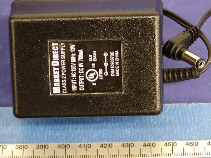
Click to zoom
Application Details
- Equipment Class
- DSS - Part 15 Spread Spectrum Transmitter
- Date of Grant
- Nov 30, 2004
- Application Purpose
- Original Equipment
- Date of Application
- Nov 30, 2004
- Equipment Note
- Digital Cordless Telephone System / Caller ID-Base
- Frequency Range
- 5760.72000000 - 5838.41000000
- Country
- Hong Kong
Documents & Files
Document Text
Text extracted from the exhibit documents filed with the FCC. Open a document above to read the original.
Users Manual
MD220 5.8GHz Digital Cordless Phone with Basic Caller ID Type 2.0/2.5 User’s Guide 1 E QUIPMENT A PPROVAL I NFORMATION Your telephone equipment is approved for connection to the Public Switched Telephone Network and is in compliance with parts 15 and 68, FCC Rules and Regulations and the Technical Requirements for Telephone Terminal Equipment published by ACTA. 1. Notification to the Local Telephone Company On the bottom of this equipment is a label indicating, among other information, the US number and Ringer Equivalence Number (REN) for the equipment. You must, upon request, provide this information to your telephone company. The REN is useful in determining the number of devices you may connect to your telephone line and still have all of these devices ring when your telephone number is called. In most (but not all) areas, the sum of the RENs of all devices connected to one line should not exceed 5. To be certain of the number of devices you may connect to your line as determined by the REN, you should contact your local telephone company. A plug and jack used to connect this equipment to the premises wiring and telephone network must comply with the applicable FCC Part 68 rules and requirements adopted by the ACTA. A compliant telephone cord and modular plug is provided with this product. It is designed to be connected to a compatible modular jack that is also compliant. See installation instructions for details. Notes z This equipment may not be used on coin service provided by the telephone company. z Party lines are subject to state tariffs, and therefore, you may not be able to use your own telephone equipment if you are on a party line. Check with your local telephone company. z Notice must be given to the telephone company upon permanent disconnection of your telephone from your line. z If your home has specially wired alarm equipment connected to the telephone line, ensure the installation of this product does not disable your alarm equipment. If you have questions about what will disable alarm equipment, consult your telephone company or a qualified installer. 2. Rights of the Telephone Company Should your equipment cause trouble on your line which may harm the telephone network, the telephone company shall, where practicable, notify you that temporary discontinuance of service may be required. Where prior notice 2 is not practicable and the circumstances warrant such action, the telephone company may temporarily discontinue service immediately. In case of such temporary discontinuance, the telephone company must: (1) promptly notify you of such temporary discontinuance; (2) afford you the opportunity to correct the situation; and (3) inform you of your right to bring a complaint to the Commission pursuant to procedures set forth in Subpart E of Part 68, FCC Rules and Regulations. The telephone company may make changes in its communications facilities, equipment, operations or procedures where such action is required in the operation of its business and not inconsistent with FCC Rules and Regulations. If these changes are expected to affect the use or performance of your telephone equipment, the telephone company must give you adequate notice, in writing, to allow you to maintain uninterrupted service. INTERFERENCE INFORMATION This device complies with Part 15 of the FCC Rules. Operation is subject to the following two conditions: (1) This device may not cause harmful interference; and (2) This device must accept any interference received including interference that may cause undesired operation. This equipment has been tested and found to comply with the limits for a Class B digital device, pursuant to Part 15 of the FCC Rules. These limits are designed to provide reasonable protection against harmful interference in a residential installation. This equipment generates, uses, and can radiate radio frequency energy and, if not installed and used in accordance with the instructions, may cause harmful interference to radio communications. However, there is no guarantee that interference will not occur in a particular installation. If this equipment does cause harmful interference to radio or television reception, which can be determined by turning the equipment off and on, the user is encouraged to try to correct the interference by one or more of the following measures: z Reorient or relocate the receiving antenna (that is, the antenna for radio or television that is “receiving” the interference). z Reorient or relocate and increase the separation between the telecommunications equipment and receiving antenna. z Connect the telecommunications equipment into an outlet on a circuit different from that to which the receiving antenna is connected. 3 If these measures do not eliminate the interference, please consult your dealer or an experienced radio/television technician for additional suggestions. Also, the Federal Communications Commission has prepared a helpful booklet, “How To Identify and Resolve Radio/TV Interference Problems.” This booklet is available from the U.S. Government Printing Office, Washington, D.C. 20402. Please specify stock number 004-000-00345-4 when ordering copies. CAUTION / WARNING: Changes or modifications not expressly approved by Market Direct could void not only the user’s authority to operate the equipment, but also the limited warranty. H EARING A ID C OMPATIBILITY (HAC) This telephone system meets FCC standards for Hearing Aid Compatibility. FCC RF Radiation Exposure Statement This equipment complies with FCC RF radiation exposure limits set forth for an uncontrolled environment. This equipment should be installed and operated with a minimum distance of 20 centimeters between the radiator and your body. This transmitter must not be c0-located or operated in conjunction with any other antenna or transmitter. For body worn operation, this phone has been tested and meets the FCC RF exposure guidelines when used with the belt clip supplied with this p…
Text truncated - open the document above for the full version.
External Photos
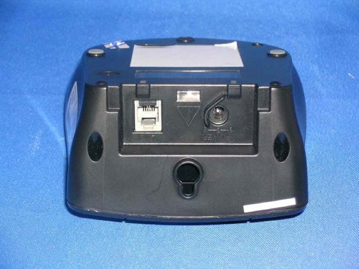
EXHIBIT C - EUT EXTERNAL PHOTOGRAPHS Base - Top View Base - Bottom View Base - Port View Power Supply - Top View Power Supply - Bottom View
ID Label/Location Info
EXHIBIT C - EUT EXTERNAL PHOTOGRAPHS Base - Top View Base - Bottom View Base - Port View Power Supply - Top View Power Supply - Bottom View
Internal Photos
EXHIBIT C - EUT INTERNAL PHOTOGRAPHS Base - Chassis Cover off View Base - Main Board Component View Base - Main Board Solder View Base - Page Board Component View I Base - Page Board Component View II Base - Page Board Solder View I Base - Page Board Solder View II
Operational Description
Page 2 of 34 CCT Confidential 13 March 2003 Table of Contents DEFINITIONS, ACRONYMS AND ABBREVIATIONS..........................................................4 1 INTRODUCTION..................................................................................................................5 1.1 SCOPE...................................................................................................................................5 2 BRIEF SYSTEM DESCRIPTION.......................................................................................6 2.1 FREQUENCY CHANNELS........................................................................................................6 2.2 TDMA FRAMES STRUCTURE................................................................................................7 2.3 RESIDENTIAL / DOMESTIC SYSTEM.......................................................................................7 2.4 BEARERS...............................................................................................................................8 3 OVERVIEW OF FREQUENCY HOPPING ALGORITHM..........................................10 3.1 HOPPING RATE....................................................................................................................10 3.2 HOPPING SEQUENCE...........................................................................................................10 3.2.1 HOPPING PATTERN BASE-TABLE........................................................................................10 3.2.2 LCG RANDOM NUMBER GENERATOR................................................................................12 3.2.3 LOGICAL AND PHYSICAL CHANNEL NUMBERS...................................................................12 3.3 IDENTIFYING CHANNEL INTERFERENCE.............................................................................14 3.4 HOP SEQUENCE ADAPTION.................................................................................................14 3.5 STARTING A DUMMY BEARER.............................................................................................14 3.5.1 AVOIDING DUMMY BEARER ‘SEQUENCE COLLISION’.........................................................14 3.6 GAINING SYNC WITH A DUMMY BEARER............................................................................15 3.6.1 DETERMINING THE PATTERN AND HSI FROM AN N T MESSAGE..........................................15 3.7 FOLLOWING A DUMMY BEARER.........................................................................................15 3.8 STARTING A TRAFFIC BEARER............................................................................................16 3.8.1 AVOIDING TRAFFIC BEARER ‘SEQUENCE COLLISION’.........................................................16 3.9 STARTING A COMBINED DUMMY/TRAFFIC BEARER............................................................16 3.9.1 AVOIDING COMBINED DUMMY/TRAFFIC BEARER ‘SEQUENCE COLLISION’.........................17 3.10 SEAMLESS BEARER HAND-OVER & “MULTI-SLOT MODE”..................................................17 3.11 HANDSET-TO-HANDSET MODE...........................................................................................17 3.12 SCANNING FOR NOISE.........................................................................................................17 4 CONFORMANCE TO FCC REQUIREMENTS..............................................................18 4.1 SECTION 15.247(A)(1)........................................................................................................18 4.2 SECTION 15.247(B)(1)........................................................................................................18 FCC Submission For 2.4GHz FHSS System D30006 Rev 0.1 13 March 2003 DSP Group Confidential Page 3 of 34 4.3 SECTION 15.247(G).............................................................................................................18 4.4 SECTION 15.247(H).............................................................................................................19 APPENDIX A – CHANNEL CENTRE FREQUENCIES........................................................20 APPENDIX B – BASE TABLE HOPPING SEQUENCE........................................................21 APPENDIX C – LCG RANDOM HOPPING SEQUENCE.....................................................23 APPENDIX D – LOGICAL TO PHYSICAL MAPPING TABLE.........................................32 Page 4 of 34 CCT Confidential 13 March 2003 DEFINITIONS, ACRONYMS AND ABBREVIATIONS Channel collision The simultaneous occupancy of a hopping channel by multiple transmitters. DECT Digital Enhanced Cordless Telecommunications. EIRP Equivalent isotropically Radiated Power. ETSI European Telecommunications Standards Institute. FCC Federal Communications commission (the body in the USA that regulates the use of the radio spectrum). FH Frequency Hopper: the name of the software component responsible for frequency hopping. FHSS Frequency Hopping Spread Spectrum. FP Fixed Part or base-station. Hand-over A process by which a second traffic bearer is established to carry an existing call. Once established the first traffic bearer can be released. HSI Hope Sequence Index: used to index into the pattern table. ISM Industrial, Scientific, Medical band: a radio frequency band in the range 2400 – 2483.5 MHz LCG Linear Congruential Generator: a type of random number generator LDC Low Duty Cycle: a power saving feature. OET Office of Engineering and Technology, a division of the FCC. PP Portable Part or handset. PSCN Primary Scan Carrier Number; used in DECT. PSPN Primary Scan Pattern Number; the analogue of the PSCN for frequency hopping. Radio Cell The area covered by a single FP. RFPI Radio Fixed Part Identity RNG Random Number Generator; more accurately a Pseudo-Random Number Generator or PRNG. RSSI Received Signal Strength Indication. Sequence collision When two transmitters, with overlapping radio cells, are u…
Text truncated - open the document above for the full version.
RF Exposure Info
§15.247 (b)(4) - RF EXPOSURE According to §15.247(b)(4) and §1.1307(b)(1), systems operating under the provisions of this section shall be operated in a manner that ensures that the public is not exposed to radio frequency energy level in excess of the Commission’s guidelines. According to §1.1310 and §2.1093 RF exposure is calculated. Limits for Maximum Permissive Exposure (MPE) Frequency Range (MHz) Electric Field Strength (V/m) Magnetic Field Strength (A/m) Power Density (mW/cm 2 ) Averaging Time (minute) Limits for General Population/Uncontrolled Exposure 0.3-1.34 614 1.63 *(100) 30 1.34-30 824/f 2.19/f *(180/f 2 ) 30 30-300 27.5 0.073 0.2 30 300-1500 / / f/1500 30 1500-15000 / / 1.0 30 f = frequency in MHz * = Plane-wave equivalent power density MPE Prediction Predication of MPE limit at a given distance Equation from page 18 of OET Bulletin 65, Edition 97-01 S = PG/4πR² Where: S = power density P = power input to antenna G = power gain of the antenna in the direction of interest relative to an isotropic radiator R = distance to the center of radiation of the antenna Maximum peak output power at antenna input terminal: 19.88 (dBm) Maximum peak output power at antenna input terminal: 97.27 (mW) Prediction distance: 20 (cm) Predication frequency: 5800 (MHz) Antenna Gain (typical): 0 (dBi) Maximum antenna gain: 1(numeric) Power density at predication frequency at 20 cm: 0.019(mW/cm^2) MPE limit for uncontrolled exposure at prediction frequency: 1.0 (mW/cm^2) Test Result The predicted power density level at 20 cm is 0.019 mW/cm^2. This is below the uncontrolled exposure limit of 1mW/cm^2 at 5800 MHz. The EUT is used at least 20cm away from user’s body. It is determined as mobile equipment.
Test Report
Note: This test report is specially limited to the above client company and product model only. It may not be duplicated without prior written consent of Bay Area Compliance Laboratory Corporation. This report must not be used by the client to claim product certification, approval, or endorsement by NVLAP, NIST or any agency of the U.S. Government. FCC PART 15.247 EMI MEASUREMENT AND TEST REPORT For CCT R & D Limited 18F., CCT Telecom Building, 11 Wo Shing Street, Fo Tan, Shatin, N.T. FCC ID: NC8MD220 This Report Concerns: Original Report Equipment Type: Digital Cordless Telephone System w/ Caller ID – Base Test Engineer: Snell Leong Report No.: R0410184(B) Report Date: 2004-11-08 Reviewed By: Daniel Deng Prepared By: Bay Area Compliance Laboratory Corporation (BACL) 230 Commercial Street Sunnyvale, CA 94085 Tel: (408) 732-9162 Fax: (408) 732 9164 CCT R & D Limited FCC ID: NC8MD220 Report # R0410184(B)Rpt Page 2 of 38 FCC Part 15.247 Test Report TABLE OF CONTENTS GENERAL INFORMATION......................................................................................................................................................4 PRODUCT DESCRIPTION FOR EQUIPMENT UNDER TEST (EUT)...............................................................................................4 OBJECTIVE.......................................................................................................................................................................................4 RELATED SUBMITTAL(S)/GRANT(S)............................................................................................................................................4 TEST METHODOLOGY....................................................................................................................................................................4 TEST FACILITY................................................................................................................................................................................4 SYSTEM TEST CONFIGURATION........................................................................................................................................5 JUSTIFICATION................................................................................................................................................................................5 EUT EXERCISE SOFTWARE...........................................................................................................................................................5 SPECIAL ACCESSORIES..................................................................................................................................................................5 SCHEMATICS / BLOCK DIAGRAM.................................................................................................................................................5 EQUIPMENT MODIFICATIONS........................................................................................................................................................5 LOCAL SUPPORT EQUIPMENT LIST AND DETAILS.....................................................................................................................5 EXTERNAL I/O CABLING LIST AND DETAILS.............................................................................................................................5 CONFIGURATION OF TEST SYSTEM..............................................................................................................................................6 TEST SETUP BLOCK DIAGRAM.....................................................................................................................................................6 SUMMARY OF TEST RESULTS FOR FCC PART 15......................................................................................................7 ANTENNA REQUIREMENT.....................................................................................................................................................8 §15.207(A) - CONDUCTED EMISSION..................................................................................................................................9 MEASUREMENT UNCERTAINTY....................................................................................................................................................9 TEST SETUP.....................................................................................................................................................................................9 SPECTRUM ANALYZER SETUP......................................................................................................................................................9 TEST EQUIPMENT LIST AND DETAILS..........................................................................................................................................9 TEST PROCEDURE...........................................................................................................................................................................9 ENVIRONMENTAL CONDITIONS....................................................................................................................................................9 SUMMARY OF TEST RESULTS......................................................................................................................................................10 CONDUCTED EMISSIONS TEST DATA.........................................................................................................................................10 PLOT OF CONDUCTED EMISSIONS TEST DATA.........................................................................................................................10 §15.205 & §15.209 - RADIATED EMISSION.......................................................................................................................13 MEASUREMENT UNCER…
Text truncated - open the document above for the full version.
Test Setup Photos
EXHIBIT B - TEST SETUP PHOTOGRAPHS Conducted Emission - Front View Conducted Emission - Side View Radiated Emission - Front View Radiated Emission - Rear View
Contact Information
Applicant
Ronilo Paredes(Senior Approval Engineer)
Test Firm
Bay Area Compliance LaboratoryJohn Chan
Technical Specifications
| # | Rule Parts | Frequency Range | Power Output |
|---|---|---|---|
| 1 | 15C | 5.76 GHz - 5.84 GHz | 97.00 mW |
Other Applications from CCT Tech Advanced Products Limited
NC8P9122G
May 16, 2007900MHz 40Ch Analog Modulation Cordless Phonew/CID
Equipment Class
DXT - Part 15 Low Power Transceiver, Rx Verified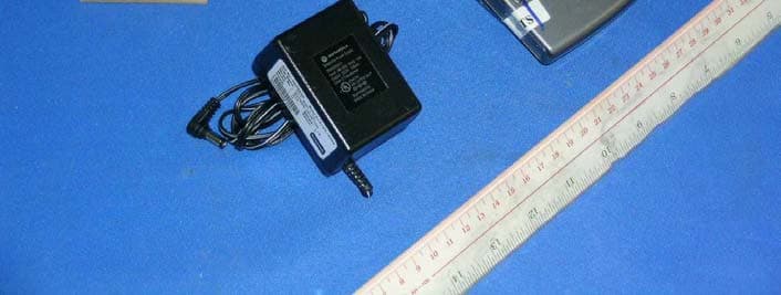
NC8SD7505
Sep 12, 20065.8GHz FHSS CellDock w/ Bluetooth
Equipment Class
DXT - Part 15 Low Power Transceiver, Rx Verified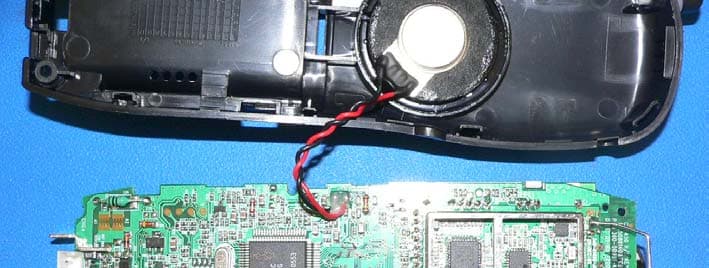
NC8CT5450
Aug 14, 20065.8GHz Cordless Phone
Equipment Class
DSS - Part 15 Spread Spectrum Transmitter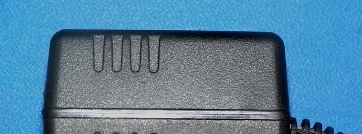
NC8MD2400
Jun 11, 20062.4Gz Cordless Phone
Equipment Class
DSS - Part 15 Spread Spectrum Transmitter
NC8KX-TG2120
May 24, 20062.4GHz/900MHz Analog Cordless phone w/ CID (Base)
Equipment Class
DXT - Part 15 Low Power Transceiver, Rx Verified