NC8MD4512.4GHz FHSS Cordless phone w/ CID, and DAM
CCT Tech Advanced Products Limited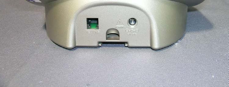
Click to zoom
Application Details
- Equipment Class
- DSS - Part 15 Spread Spectrum Transmitter
- Date of Grant
- Apr 28, 2004
- Application Purpose
- Original Equipment
- Date of Application
- Apr 28, 2004
- Equipment Note
- 2.4GHz FHSS Cordless phone w/ CID, and DAM
- Frequency Range
- 2401.80845200 - 2478.50935800
- Country
- Hong Kong
Documents & Files
Document Text
Text extracted from the exhibit documents filed with the FCC. Open a document above to read the original.
Users Manual
User’s Guide > MD490 Series Digital 2.5 GHz Cordless TelephoneSystem 1 Welcome Congratulations on your purchase of a Motorola product! Product registration is an important step. Registering helps us facilitate warranty service and permits us to contact you if your Motorola product requires an update or other service. To register your product online, visit: www.motorola.com/warranty/cordless Please retain your original dated sales receipt for your records. For warranty service of your Motorola product, you will need to provide a copy of your dated sales receipt to confirm warranty status. Registration is not required for warranty coverage. For a large-print version of this guide, or for product- related questions, please call: 1-800-353-2729 in the USA 1-888-390-6456 TTY (Text Telephone) On the Web: www.motorola.com/cordless MOTOROLA and the Stylized M Logo are registered in the US Patent & Trademark Office. All other product or service names are the property of their respective owners. © Motorola, Inc. 2003 6864110W32-O 2 Base Station Controls Soft Keys The left and right soft keys perform the function displayed. For example, pressing the left soft key while PHONEBK is displayed, opens your list of phone numbers and names. page del in use/ voice mail charge/ page memo 031388o Scroll up or down on display Record a memo Left soft key Right soft key i Play/stop message h Skip backwards g Skip forwards f Delete message Page a handset Intercom Handsfree 3 FCC and Interference Information FCC and Interference Information This equipment complies with Parts 15 and 68 of the FCC rules and the requirements adopted by the Administrative Council for Terminal Attachments (ACTA). A plug and jack used to connect this equipment to the premises wiring and telephone network must comply with applicable FCC Part 68 rules and requirements adopted by the ACTA. A compliant telephone cord and modular plug is provided with this product. It is designed to be connected to a compatible modular jack that is also compliant. See installation instructions for details. Notification of the Local Telephone Company On the bottom of this equipment is a label that contains, among other information, a product identifier in the form US:AAAEQ##TXXXX. You must, upon request, provide this information to your telephone company. The digits represented by ## in the product identifier indicate the Ringer Equivalency Number (REN) for this equipment. The REN is useful in determining the number of devices you may connect to your telephone line and still have all of these devices ring when your telephone number is called. In most (but not all) areas, the sum of the RENs of all devices connected to one line should not exceed 5. To be certain of the number of devices you may connect to your line as determined by the REN, contact your local telephone company. Notes: •This equipment may not be used on coin service provided by the telephone company. •Connection to party line service is subject to state tariffs. Contact the state public utility commission, public service commission or corporation commission for information. 4 FCC and Interference Information •If your home has specially wired alarm equipment connected to the telephone line, ensure the installation of this cordless phone does not disable your alarm equipment. If you have questions about what will disable alarm equipment, consult your telephone company or a qualified installer. •Notice must be given to the telephone company upon permanent disconnection of your telephone from your line. •The FCC requires that you connect your cordless telephone to the nationwide telephone network through a modular telephone jack (USOC RJ11C/RJ11W or RJ14C/RJ14W). Rights of the Telephone Company Should your equipment cause trouble on your line which may harm the telephone network, the telephone company shall, where practicable, notify you that temporary discontinuance of service may be required. Where prior notice is not practical and the circumstances warrant such action, the telephone company may temporarily disconnect service immediately. In case of such temporary discontinuance, the telephone company must: 1. Promptly notify you of such temporary discontinuance; 2. Afford you the opportunity to correct the situation; 3. Inform you of your right to bring a complaint to the Commission pursuant to procedures set forth in Subpart E of Part 68, FCC Rules and Regulations. The telephone company may make changes in its facilities, equipment, operations, or procedures that could affect the operation of the equipment. If this happens, the telephone company will provide advance notice in order for you to make necessary modifications to maintain uninterrupted service. 5 FCC and Interference Information Interference Information This device complies with Part 15 of the FCC Rules. Operation is subject to the following two conditions: 1. This device may not cause harmful interference. 2. This device must accept any interference received, including interference that may cause undesired operation. This equipment has been tested and found to comply with the limits for a Class B digital device, pursuant to Part 15 of the FCC Rules. These limits are designed to provide reasonable protection against harmful interference in a residential installation. This equipment generates, uses, and can radiate radio frequency energy and, if not installed and used in accordance with the instructions, may cause harmful interference to radio communications. However, there is no guarantee that interference will not occur in a particular installation. If this equipment does cause harmful interference to radio or television reception, which can be determined by turning the equipment on and off, the user is encouraged to try to correct the interference with one or more of the following measures: Reorient or relocate the receiving antenna (that is, the antenna for the radio or television that is “receiving” the interference). Reorient o…
Text truncated - open the document above for the full version.
Users Manual
5 FCC and Interference Information Interference Information This device complies with Part 15 of the FCC Rules. Operation is subject to the following two conditions: 1. This device may not cause harmful interference. 2. This device must accept any interference received, including interference that may cause undesired operation. This equipment has been tested and found to comply with the limits for a Class B digital device, pursuant to Part 15 of the FCC Rules. These limits are designed to provide reasonable protection against harmful interference in a residential installation. This equipment generates, uses, and can radiate radio frequency energy and, if not installed and used in accordance with the instructions, may cause harmful interference to radio communications. However, there is no guarantee that interference will not occur in a particular installation. If this equipment does cause harmful interference to radio or television reception, which can be determined by turning the equipment on and off, the user is encouraged to try to correct the interference with one or more of the following measures: Reorient or relocate the receiving antenna (that is, the antenna for the radio or television that is “receiving” the interference). Reorient or relocate and increase the separation between the telecommunications equipment and the receiving antenna. Connect the telecommunications equipment into an outlet on a circuit different from that to which the receiving antenna is connected. 6 FCC and Interference Information If these measures do not eliminate the interference, please consult your dealer or an experienced radio/television technician for additional suggestions. Also, the Federal Communications Commission has prepared a helpful booklet, “How to Identify and Resolve Radio/TV Interference Problems.” This booklet is available from the U.S. Government Printing Office, Washington, D.C. 20402. Please specify stock number 004-000-00345-4 when ordering copies. The FCC requires this product to be serviced only by Motorola or its authorized service agents. CAUTION: Changes or modifications no t expressly approved by Motorola could void not only the user's authority to operate the eq uipment, but also the limited warranty. Hearing Aid Compatibility This telephone system meets the FCC standards for hearing aid compatibility.
External Photos
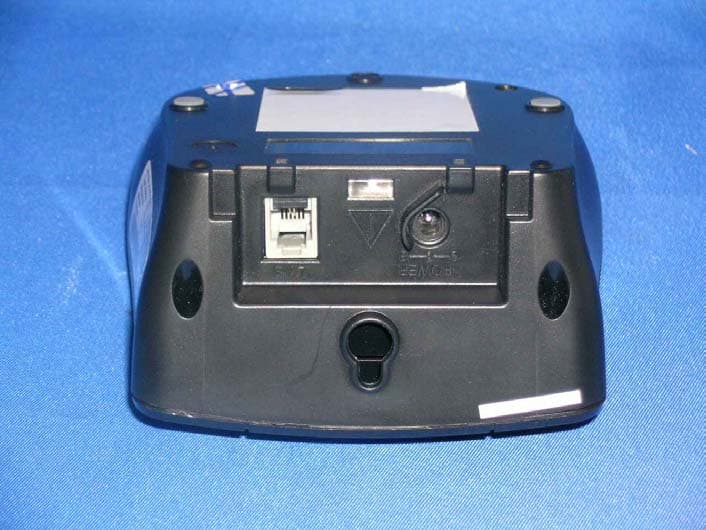
External photos FCC ID: NC8MD451 External photos FCC ID: NC8MD451
RF Exposure Info
9 Important Safety Instructions 8. Use only the power supply that came with this unit. Using other power supplies may damage the unit. 9. Because cordless phones operate on electricity, you should have at least one phone in your home that is not cordless in case the power in your home goes out. 10. To avoid interference to nearby appliances, do not place the base of the cordless phone on or near a TV, microwave oven, or VCR. Caution: To maintain compliance with the FCC’s RF exposure guidelines, place the base unit at least 20 cm from nearby persons. Battery Safety Instructions •Do not burn, disassemble, mutilate, or puncture the battery. The battery contains toxic materials that could be released, resulting in injury. •Caution: There is a risk of explosion if you replace the battery with an incorrect battery type. Use only the battery that came with your phone or an authorized replacement recommended by the manufacturer. •Keep batteries out of the reach of children. •Remove batteries if storing over 30 days. •Do not dispose of batteries in fire, which could result in explosion. •The rechargeable batteries that power this product must be disposed of properly and may need to be recycled. Refer to your battery’s label for battery type. Contact your local recycling center for proper disposal methods. ITC03-201 Intertek Testing Services FCC ID: NC8MD451 Date: March 12, 2004 For SAR evaluation of the handset, refer to TCB Exclusions List Revised on 17 July 2002. Potable transmitter with output power less than 60/fGHz (d < 2.5cm) can be certified by TCB without the SAR evaluation. In fact, the Output power for portable transmitters is the higher of the conducted or radiated (EIRP) source-based time-averaged output. And the fGHz is mid- band frequency in GHz, and d is the distance to a person’s body, excluding hands, wrists, feet, and ankles. For the tested model of MD491, the measured peak conducted power was 88.3mW and the source-based time averaged output power was 8.1mW as TX duty cycle of the handset is 9.2%. The maximum field strength (FS) was 116.6dBμV/m at 2440.159MHz. The distance (D) between the antenna and the equipment under test (EUT) was 3 meters. From these data, the EIRP can be calculated by: EIRP = (FS*D) 2 / 30 = 137.1mW Source-based time averaged output power = (137.1*0.092) mW = 12.6mW Based on the above calculation, it is concluded that the handset can be certified by TCB without the SAR evaluation.
Test Report
• The test results reported in this report shall refer only to the sample actually tested and shall not refer or be deemed to refer to bulk from which such a sample may be said to have been obtained. • This report shall not be reproduced except in full without prior authorization form Giant Electronics Limited Limited FCC ID: NC8MD451 Intertek Testing Services Hong Kong Ltd. 2/F., Garment Centre, 576 Castle Peak Road, Kowloon, Hong Kong. Tel: (852) 2173 8888 Fax: (852) 2741 1693 Website: www.hk.intertek-etlsemko.com CCT R&D Ltd. Application For Certification 2.4GHz Frequency Hopping Spread Spectrum Cordless Phone with with Caller ID, Speakerphone, and Digital Answering Machine (FCC ID: NC8MD451) 04027571 TL/Ann Choy March 30, 2004 INTERTEK TESTING SERVICES FCC ID: NC8MD451 i LIST OF EXHIBITS INTRODUCTION EXHIBIT 1: Summary of Tests EXHIBIT 2: General Description EXHIBIT 3: System Test Configuration EXHIBIT 4: Measurement Results EXHIBIT 5: Equipment Photographs EXHIBIT 6: Product Labelling EXHIBIT 7: Technical Specifications EXHIBIT 8: Instruction Manual EXHIBIT 9: Security Code Information INTERTEK TESTING SERVICES FCC ID: NC8MD451 ii MEASUREMENT/TECHNICAL REPORT CCT R&D Ltd.- MODEL: MD49X series, MD400 Series FCC ID: NC8MD451 This report concerns (check one) Original Grant X Class II Change Equipment Type: DSS-Part 15 Spread Spectrum Transmitter Deferred grant requested per 47 CFR 0.457(d)(1)(ii)? Yes No X If yes, defer until : dae Company Name agrees to notify the Commission by: date of the intended date of announcement of the product so that the grant can be issued on that date. Transition Rules Request per 15.37? Yes No X If no, assumed Part 15, Subpart C for intentional radiator - the new 47 CFR [12- 08-03 Edition] provision. Report prepared by: Tommy Leung Intertek Testing Services 2/F., Garment Centre, 576 Castle Peak Road, Kowloon, Hong Kong. Phone: 852-2173-8538 Fax: 852-2741-1693 INTERTEK TESTING SERVICES FCC ID: NC8MD451 iii Table of Contents 1.0 Summary of test results ..................................................................................... 2 2.0 General Description.................................................................................................. 4 2.1 Product Description ................................................................................................. 4 2.2 Related Submittal(s) Grants ..................................................................................... 5 2.3 Test Methodology .................................................................................................... 5 2.4 Test Facility ............................................................................................................. 5 3.0 System Test Configuration ...................................................................................... 7 3.1 Justification..............................................................................................................7 3.2 EUT Exercising Software ......................................................................................... 7 3.3 Support Equipment List and Description .................................................................. 8 3.4 Measurement Uncertainty............................................................................................. 9 3.5 Equipment Modification ........................................................................................... 9 4.0 Measurement Results............................................................................................. 11 4.1 Maximum Conducted Output Power at Antenna Terminals..................................... 11 4.2 Maximum 20 dB RF Bandwidth .............................................................................. 13 4.3 Minimum Number of Hopping Frequencies ................................................................ 15 4.4 Minimum Hopping Channel Carrier Frequency Separation........................................ 16 4.5 Average Time of Occupancy .................................................................................. 18 4.6 Out of Band Conducted Emissions ............................................................................. 19 4.7 Out of Band Radiated Emissions............................................................................ 20 4.8 Transmitter Radiated Emissions in Restricted Bands.............................................. 21 4.9 Field Strength Calculation ...................................................................................... 22 4.10 Radiated Emission Configuration Photograph - Base Unit....................................... 23 4.11 Radiated Emission Data - Base Unit..................................................................... 24 4.12 Radiated Emission Configuration Photograph - Handset....................................... 28 4.13 Radiated Emission Data - Handset ....................................................................... 29 4.14 AC Line Conducted Emission ............................................................................... 33 4.15 Line Conducted Configuration Photograph - Base Unit ......................................... 34 4.16 Line Conducted Emission Configuration Data ....................................................... 35 4.17 Radiated Emission from Digital Section of Transceiver ............................................ 36 4.18 Transmitter Duty Cycle Calculation and Measurements........................................ 39 5.0 Equipment Photographs ........................................................................................ 41 6.0 Product Labelling................................................................................................... 43 7.0 Technical Specifications ........................................................................................ 45 8.0 Instruction Manual ..............................................................................................…
Text truncated - open the document above for the full version.
Test Report
Report No.:04027571 Talk (2 Handsets) Mode Ctrl No.:N/A PAGE 1 Tested By:Hong, Report No.:04027571 Scan Settings (1 Range) |--------- Frequencies -----------||----------- Receiver Settings ------------| Start Stop Step IF BW Detector M-Time Atten Preamp OpRge 150k 30M 5k 10k PK+AV 10ms AUTO LN OFF 60dB Final Measurement: x QP / + AV Meas Time: 1 s Subranges: 16 Acc Margin: 20dB Transducer No. Start Stop Name 21 9k 30M EW0698 0 10 20 30 40 50 60 70 80 90 dBuV 100 0.15 MHz 30110 F15Q F15A Report No.:04027571 Talk (2 Handsets) Mode Ctrl No.:N/A Tested By:Hong, Report No.:04027571 Scan Settings (1 Range) |--------- Frequencies -----------||----------- Receiver Settings ------------| Start Stop Step IF BW Detector M-Time Atten Preamp OpRge 150k 30M 5k 10k PK+AV 10ms AUTO LN OFF 60dB Final Measurement Results: Frequency QP Level QP Limit MHz dBuV dBuV 0.77000 36.3 56.0 0.86500 43.7 56.0 Frequency AV Level AV Limit MHz dBuV dBuV 0.73500 31.5 46.0 0.89500 40.1 46.0 * limit exceeded
Test Setup Photos
The Worst Case Configuration Photographs FCC ID: NC8MD451 Radiated Emission – Base Front View Rear View The Worst Case Configuration Photographs FCC ID: NC8MD451 Radiated Emission – Handset Front View Rear View The Worst Case Configuration Photographs FCC ID: NC8MD451 Conducted Emission Front View Rear View The Worst Case Configuration Photographs FCC ID: NC8MD451 Conducted Emission Side View
Test Setup Photos
The Worst Case Configuration Photographs FCC ID: NC8MD451 Radiated Emission – Base Front View Rear View The Worst Case Configuration Photographs FCC ID: NC8MD451 Radiated Emission – Handset Front View Rear View The Worst Case Configuration Photographs FCC ID: NC8MD451 Conducted Emission Front View Rear View The Worst Case Configuration Photographs FCC ID: NC8MD451 Conducted Emission Side View
Contact Information
Applicant
Ronilo Paredes(Senior Approval Engineer)
Technical Contact
Intertek Testing Services Hong Kong Ltd.Tommy Leung
[email protected]852-2173-8538
2/F., Garment Centre, · Kowloon · Iran
Non-Technical Contact
Intertek Testing Services Hong Kong Ltd.Tommy Leung
[email protected]852-2173-8538
Test Firm
Intertek Testing Services Hong KongBilly Chow
Technical Specifications
| # | Rule Parts | Frequency Range | Power Output |
|---|---|---|---|
| 2 | 15C | 2.40 GHz - 2.48 GHz | 88.00 mW |
Other Applications from CCT Tech Advanced Products Limited
NC8P9122G
May 16, 2007900MHz 40Ch Analog Modulation Cordless Phonew/CID
Equipment Class
DXT - Part 15 Low Power Transceiver, Rx Verified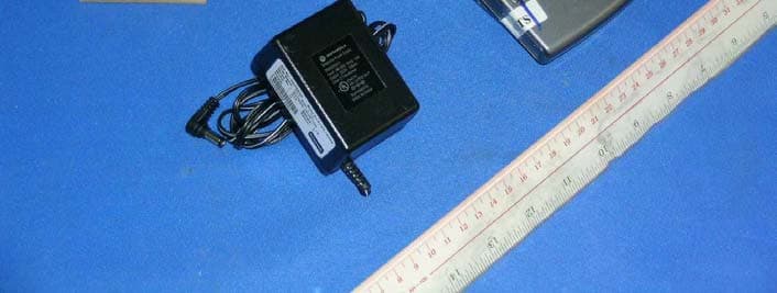
NC8SD7505
Sep 12, 20065.8GHz FHSS CellDock w/ Bluetooth
Equipment Class
DXT - Part 15 Low Power Transceiver, Rx Verified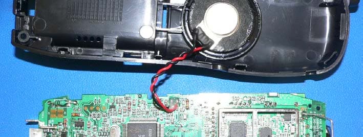
NC8CT5450
Aug 14, 20065.8GHz Cordless Phone
Equipment Class
DSS - Part 15 Spread Spectrum Transmitter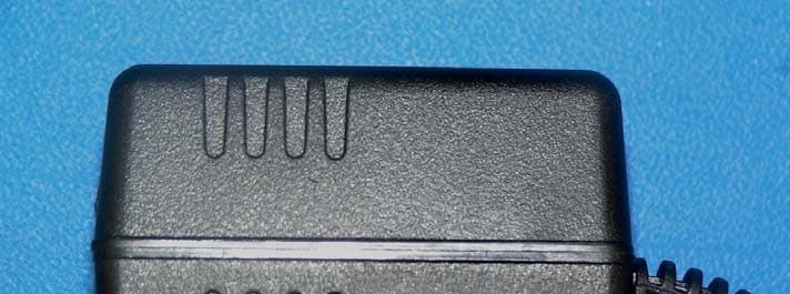
NC8MD2400
Jun 11, 20062.4Gz Cordless Phone
Equipment Class
DSS - Part 15 Spread Spectrum Transmitter
NC8KX-TG2120
May 24, 20062.4GHz/900MHz Analog Cordless phone w/ CID (Base)
Equipment Class
DXT - Part 15 Low Power Transceiver, Rx Verified