NC8T5600Transmitter Portion of FRS+GMRS
CCT Tech Advanced Products Limited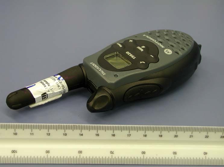
Click to zoom
Application Details
- Equipment Class
- FRF - Part 95 Family Radio Face Held Transmitter
- Date of Grant
- Jun 04, 2003
- Application Purpose
- Original Equipment
- Date of Application
- Jun 04, 2003
- Equipment Note
- Transmitter Portion of FRS+GMRS
- Frequency Range
- 467.56250000 - 467.71250000
- Country
- Hong Kong
Documents & Files
Document Text
Text extracted from the exhibit documents filed with the FCC. Open a document above to read the original.
Users Manual
Models T5600, T5620, T5700, T5710, T5720 @6881042B60@ 6881042B60-A 021024a.eps 1042b60a.book Page 1 Friday , January 17, 2003 2:43 PM 1042b60a.book Page 2 Friday , January 17, 2003 2:43 PM Introduction 1 IntroductionCongratulations on your purchase of a Motorola product!Product registration is an important step. Registering helps us facilitate warranty service and permits us to contact you should your Motorola product require an update or other service. To register your product on-line, visit www.motorola.com/warranty/radios . Please retain your original dated sales receipt for your records. For warranty service of your Motorola product, you will need to provide a copy of your dated sales receipt to confirm warr anty status. Registration is not required for warranty coverage. For a copy of a large-print version of this guide, or for product-related questions, call: 1-800-353-2729 in the USA 1-888-390-6456 TTY (Text Telephone) On the web, please refer to www.motorola.com/talkabout 1042b60a.book Page 1 Friday , January 17, 2003 2:43 PM Contents 2 Contents Introduction . . . . . . . . . . . . . . . . . . . . . 1Safety and General In formation . . . . 3 FCC Licensing Information . . . . . . . 11Control Buttons - Models T5600, T5700 . . . . . . . . . . . . . . . . . . . . . . . . 12 Control Buttons - Models T5620, T5710, T5720 . . . . . . . . . . . . . . . . . 13 Getting Started . . . . . . . . . . . . . . . . . 14 Installing the AA Batteries . . . . . . . . . . .14Installing the NiCd Battery Pack . . . . . .14Battery Meter . . . . . . . . . . . . . . . . . . . .15Using the Desk Stand Charger (Optional Accessory) . . . . . . . . . . . .15 Attaching the Belt Clip . . . . . . . . . . . . . .17Removing the Belt Clip . . . . . . . . . . . . .17Turning Your Radio On and Off . . . . . .17Setting the Volume . . . . . . . . . . . . . . . .17Setting a Channel . . . . . . . . . . . . . . . . .18Channels and Frequencies . . . . . . . . . .19 Talking and Listening . . . . . . . . . . . . 20 Talk Range . . . . . . . . . . . . . . . . . . . . . .20Checking the Channel Before Transmitting . . . . . . . . . . . . . . . . . . .20 Special Features . . . . . . . . . . . . . . . . .21 Interference Eliminator Code . . . . . . . . 21Push to Talk Timeout Timer . . . . . . . . . 21Locking the Keypad . . . . . . . . . . . . . . . 22Scanning Channels (Models T5620, T5700, T5710 Only) . . . . . . . . . . . . . 22 Scan Advance . . . . . . . . . . . . . . . . . . . 23Removing Channels from the Scan List (Nuisance Delete Feature) . . . . . . . . 23 Alerts . . . . . . . . . . . . . . . . . . . . . . . . . .24 Channel Busy Indicator . . . . . . . . . . . . 24Setting and Transmitting Call Tones . . 24Transmitting a Talk Confirmation Tone 25QT Noise Filtering (Models T5700, T5710, T5720 Only) . . . . . . . . . . . . . 25 Accessories . . . . . . . . . . . . . . . . . . . .27 Using Audio Accessories . . . . . . . . . . . 27Voice Activation (VOX) Accessories (Models T5710, T5720 Only) . . . . . . 27 Setting the Sensitivity Level (Models T5710, T5720 Only) . . . . . . 28 Patent Information . . . . . . . . . . . . . . .29Export Law Assurances . . . . . . . . . .29 1042b60a.book Page 2 Friday , January 17, 2003 2:43 PM Safety and General Information 3 Safety and General InformationImportant Information on Safe and Efficient OperationRead This Information Before Using Your RadioThe information provided in this document supersedes the general safety information contained in user guides published prior to July 2000.Transmit and Receive ProcedureYour two-way radio contains a transmitter and a receiver. To control your exposure and ensure compliance with the general population/uncontrolled environment exposure limits, always adhere to the following procedure: • Transmit no more than 50% of the time. • To transmit (talk), press the Push to Talk (PTT) button. • To receive calls, release the PTT button. Transmitting 50% of the time, or less, is important because the radio generates measurable RF energy exposure only when transmitting (in terms of measuring standards compliance).Exposure to Radio Frequency EnergyYour Motorola radio is designed to comply with the following national and international standards and guidelines regarding exposure of human beings to radio frequency electromagnetic energy:• United States Federal Communications Commission, Code of Federal Regulations; 47 CFR part 2 sub-part J 1042b60a.book Page 3 Friday , January 17, 2003 2:43 PM Safety and General Information 4 • American National Standards Institute (ANSI)/Institute of Electrical and Electronic Engineers (IEEE) C95. 1-1992 • Institute of Electrical and Electronic Engineers (IEEE) C95.1-1999 Edition • International Commission on Non-Ionizing Radiation Protection (ICNIRP) 1998 • Ministry of Health (Canada) Safety Code 6. Limits of Human Exposure to Radio Frequency Electromagnetic Fields in the Frequency Range from 3 kHz to 300 GHz, 1999 • Australian Communications Authority Radiocommunications (Electromagnetic Radiation - Human Exposure) Standard 2001 (applicable to wireless phones only) • ANATEL, Brasil Regulatory Authority, Resolution 256 (April 11, 2002) “additional requirements for SMR, cellular, and PCS product certification.” To assure optimal radio performance and make sure human exposure to radio frequency electromagnetic energy is within the guidelines set forth in the above standards, always adhere to the following procedures.Portable Radio Operation and EME ExposureAntenna CareUse only the supplied or an approved rep lacement antenna. Unauthorized antennas, modifications, or attachments could damage the radio and may violate FCC regulations. DO NOT hold the antenna when the radio is “IN USE.” Holding the antenna affects the effective range. 1042b60a.book Page 4 Friday , January 17, 2003 2:43 PM Safety and General Information 5 Two-Way Radio OperationWhen using your radio as a traditional two-way radio, hold the radio in a vertical position with the micro…
Text truncated - open the document above for the full version.
External Photos
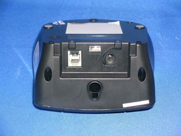
Test Setup FCCID : NC8T5600 External Photo -front External Photo - rear
Internal Photos
Test Setup FCCID : NC8T5600 Internal Photo - 1 Internal Photo - 2 Test Setup FCCID : NC8T5600 Internal Photo – 3 Internal Photo – 4 Test Setup FCCID : NC8T5600 Internal Photo – 5
Parts List/Tune Up Info
ALIGNMENT PROCEDURE Models: T5600/T56200 1. Recommended Test Equipment 1.1 HP8920A Communication Test Set 1.2 Fluke 50S Digital Thermometer 1.3 Fluke 77 Digital Voltmeter 1.4 Power Supply 2. Test Preparation 2.1 Connect a 4.5Vdc power source to the positive terminal input point and the negative battery input point (GND) for negative terminal. 2.2 Connect a communications service monitor capable of at least two watt RF to antenna test point. 2.3 Connect a 1/2watt 16ohm resistor from speaker +SP to -SP. 2.4 Test point +SP should be connected to Audio In HI of the HP8920A. 2.5 Test point –SP should be connected to Audio In LO of the HP8920A. 3. Voltage Regulator Test 3.1 Connect a voltmeter to output of regulator Bvout and measure the voltage. The DC value must be between 2.94 and 3.06Vdc. 4. Temperature Compensation Alignment 4.1 Connect a voltmeter to TP18 (THERM_DET). 4.2 Record the current ambient temperature (TA). 4.3 From the temperature compensation alignment table, determine the target voltage (Vthem) based on the ambient temperature (TA). 4.4 Select one resistor from R303 to R305 until the voltmeter reading is close to the target voltage (Vthem). R306 is used to fine tune the voltage (Vthem). Temperature Compensation Alignment Table Temp/C Vthem/V Temp/C Vthem/V 15 0.908 26 0.599 16 0.875 27 0.576 17 0.844 28 0.554 18 0.813 29 0.533 19 0.783 30 0.512 20 0.754 31 0.492 21 0.726 32 0.473 22 0.699 33 0.455 23 0.673 34 0.438 24 0.647 35 0.421 25 0.623 5. Battery Low Alignment 5.1 Connect a voltmeter to TP17 (BATT_DET). 5.2 Adjust power supply to 3.60Vdc +/- 50mV. 5.3 Select one resistor from R300 to R302 until the voltmeter reading is close to 2.4Vdc +/- 100mV. 6. Battery Low Test 6.1 Connect 3 rd _TERM to GND. 6.2 Adjust power supply to 3.45Vdc +/- 50mV. 6.3 Cycle power by turning the unit Off then On. 6.4 Insure the battery low does not alert. 6.5 Adjust power supply to 3.35Vdc +/- 50mV. 6.6 Cycle power by tuning the unit Off then On. 6.7 Insure the battery low does alert. 6.8 Readjust power supply to 4.5Vdc. 7. VCO Alignment 7.1 Set unit to Channel 15 and connect a voltmeter to TP16 (VCO PD). 7.2 Press the PTT switch so unit is in transmit mode. 7.3 Adjust VC1 until the voltmeter read 0.8V. VC1 is located under the VCO shield can and is accessible through the hole cut-out. 7.4 Release the PTT switch and observe the voltage on TP16 (VCO PD). The voltage should be in the range of 0.4 to 1.0Vdc. 7.5 Set unit to channel 14 and connect a voltmeter to TP16 (VCO PD). 7.6 Press the PTT switch and observe the voltage on TP16 (VCO PD). The voltage should be between 1.0 to 2.0Vdc. 7.7 Release PTT and observe the voltage on TP16 (VCO PD). The voltage should be between 1.0 and 2.0Vdc. 8. Transmitter Frequency Alignment 8.1 Press the PTT switch so unit is in transmit mode. 8.2 Adjust VC2 such that the output frequency is equal to the channel frequency with a maximum error +/-200Hz (QC limit of +/-500Hz). VC2 is located near the crystal unit of X1. 9. Transmitter Output Power Check 9.1 Set unit to channel 1. 9.2 Connect 3 rd _TERM to GND. 9.3 Press the PTT switch so unit is in transmit mode. 9.4 Transmit power should be between 24dBm +/- 2. 9.5 Set unit to channel 14. 9.6 Press the PTT switch so unit is in transmit mode. Ensure that Tx Power is between 24dBm +/- 2. 9.7 Set unit to channel 1. 9.8 Disconnect 3 rd _Term from GND. Leave 3 rd _Term open. 9.9 Reduce battery voltage from 4.5Vdc to 3.6Vdc. 9.10 Press the PTT switch so unit is in transmit mode. 9.11 Transmit power should be between 24dBm +/- 2. 9.12 Set unit to channel 14. 9.13 Press the PTT switch so unit is in transmit mode. Ensure that Tx Power is between 24dBm +/- 2. 9.14 Reset battery voltage to 4.5Vdc. 10. Transmitter Deviation Adjustment 10.1 Connect an audio generator (600ohm) to the microphone test points MIC+ and GND. The audio frequency should be set a 1kHz with a level of 50mv RMS. 10.2 Connect an FM deviation meter (communication test set) to antenna test point. Set the deviation meter to read peak to peak divided by two deviation. Set Filter 1 to 50Hz HPF. Set Filter 2 to 15kHz LPF. 10.3 Press the PTT switch so unit is in transmit mode. 10.4 Adjust VR4 for 2kHz deviation (+/-5%). 10.5 Decrease audio generator level until deviation reads +/- 1.5kHz and record generator level. Level should be between 5mV and 15mV. 10.6 Set Filter 1 to 300Hz HPF. Set Filter 2 to 3kHz LPF. Make sure to turn on de-emphasis. 10.7 Check that transmit audio distortion is less than 5%. 10.8 Switch off the audio generator. 10.9 Set Filter 1 to 50Hz HPF. Set Filter 2 to 300Hz LPF. 10.10 Set unit to channel 1 with CTCSS code 1. 10.11 Check that the CTCSS code deviation is in the range between +/- 300 to 450Hz. 10.12 Repeat step 10.11 for channel 1 with CTCSS code 38. 10.13 Repeat step 10.11 for channel 14 with CTCSS code 1. 10.14 Repeat step 10.11 for channel 14 with CTCSS code 38. 11 Receiver Alignment 11.1 Set Filter 1 to 300Hz HPF. Set Filter 2 to 3kHz LPF. 11.2 Set the output level of the RF signal generator for –47dBm. The generator should be set for 1.5kHz deviation at 1kHz modulation. 11.3 Set the audio output level for 25-35mW by adjusting volume. 11.4 Adjust IFT1 for maximum audio output. IFT1 is located to the right of the 450kHz ceramic filter. 11.5 Check that RX audio distortion is less than 5%. 11.6 Check that RX Sensitivity is less than –118dBm by reducing the output level of the RF signal generator until a 12dB SINAD reading is achieved. 12 Squelch Threshold and Hysteresis 12.1 Set CTCSS code to 0. 12.2 Reduce signal generator level to its minimum level. 12.3 Increase level in 1dB steps until the unit opens squelch and has steady audio output. This should occur at or below –120dBm. 12.4 Reduce signal generator level until the unit squelches. The difference between generator levels for “open” vs. “squelched” should be 1-5dB. 12.5 Set up the signal generator to channel 1 with Audio Gen #1 set for 1.5kHz deviation at 1kHz modulation and Audio…
Text truncated - open the document above for the full version.
Test Report
Modulation Frequency Response 0.00 0.50 1.00 1.50 2.00 20070012001700220027003200370042004700 Modulation Frequency (Hz) Frequency Deviation (kHz) Modulation Frequency Response 0.00 0.50 1.00 1.50 30080013001800230028003300380043004800 Modulation Frequency (Hz) Modulation Index (%)
Test Report
Modulation Limiting Characteristic 0.00 0.50 1.00 1.50 2.00 2.50 475767778797107117127137 Modulation Input (dBSPL) Frequency Deviation (kHz) 500Hz 1000Hz 2500Hz 3125Hz
Test Report
• The test results reported in this report shall refer only to the sample actually tested and shall not refer or be deemed a refer to bulk from which such a sample may be said to have been obtained. • This report shall not be reproduced except in full without prior authorization from Intertek Testing Services Hong Kong Limited • For Terms And Conditions of the services, it can be provided upon request. • The evaluation data of the report will be kept for 3 years from the date of issuance. Intertek Testing Services Hong Kong Ltd. 2/F., Garment Centre, 576 Castle Peak Road, Kowloon, Hong Kong. Tel: (852) 2173 8888 Fax: (852) 2371 0521 CCT Telecom (HK) Limited Application For Certification (FCC ID: NC8T5600) May 22, 2003 0303625 DL/Sandy May 22, 2003 INTERTEK TESTING SERVICES FCC ID: NC8T5600 i SUMMARY OF CONTENTS LIST OF EXHIBITS EXHIBIT 1: General Description EXHIBIT 2: System Test Configuration EXHIBIT 3: RF Power Output EXHIBIT 4: Modulation Characteristics EXHIBIT 5: Occupied Bandwidth EXHIBIT 6: Spurious Emission EXHIBIT 7: Frequency Stability EXHIBIT 8: Technical Specifications EXHIBIT 9: Product Labelling EXHIBIT 10: Photographs EXHIBIT 11: Instruction Manual EXHIBIT 12: Tune Up Procedure EXHIBIT 13: Part List EXHIBIT 14: Input Current EXHIBIT 15: RF Exposure Info EXHIBIT 16: Confidentiality Request INTERTEK TESTING SERVICES FCC ID: NC8T5600 ii MEASUREMENT/TECHNICAL REPORT Application : CCT Telecom (HK) Limited Trade Name/Model No : Motorola T5620 Motorola T5600 Date : May 22, 2003 This report concerns (check one:)Original Grant X Class II Change Equipment Type: GMRS + FRS Deferred grant requested per 47 CFR 0.457(d)(1)(ii)? Yes No X If yes, defer until: date Company Name agrees to notify the Commission by: date of the intended date of announcement of the product so that the grant can be issued on that date. Report prepared by: Derek Leung Intertek Testing Services 2/F., Garment Centre, 576 Castle Peak Road, Kowloon, Hong Kong. Phone: 852-2173-8504 Fax: 852-2371-0521 INTERTEK TESTING SERVICES FCC ID: NC8T5600 iii Table of Contents 1.0 General Description ............................................................................................................2 1.1 Product Description.........................................................................................................2 1.2 Related Submittal(s) Grants.............................................................................................3 1.3 Test Methodology...........................................................................................................3 1.4 Test Facility.....................................................................................................................3 2.0 System Test Configuration .................................................................................................5 2.1 Justification......................................................................................................................5 2.2 EUT Exercising Software.................................................................................................6 2.3 Special Accessories.........................................................................................................6 2.4 Measurement Uncertainty................................................................................................6 2.5 Equipment Modification....................................................................................................6 3.0 RF Output Power (Section 95.639(d)) ................................................................................8 4.0 Modulation Characteristics (Section 95.637(a)) ..............................................................12 4.1 Modulation Frequiency Response...................................................................................13 4.2 Modulation Limiting Characteristic..................................................................................15 4.3 Audio Low Pass Filter Response....................................................................................17 5.0 Occupied Bandwidth (Section 95.633(c)) ........................................................................19 6.0 Spurious Emission (Section 95.635(b)) .............................................................................21 6.1 Field Strength of Spurious Radiation..............................................................................22 7.0 Frequency Stability (Section 95.627) ...............................................................................28 7.1 Frequency Tolerance.....................................................................................................29 7.2 Temperature Extreme Condition.....................................................................................31 7.3 Voltage Extreme Condition............................................................................................34 8.0 Technical Specifications ...................................................................................................37 9.0 Product Labelling ..............................................................................................................41 10.0 Equipment Photographs ..................................................................................................44 11.0 Instruction Manual .........................................................................................................46 12.0 Tune Up Procedure .........................................................................................................48 13.0 Part List ...........................................................................................................................50 14.0 Input Current ...................................................................................................................52 15.0 RF Exposure Info ...................................................................................…
Text truncated - open the document above for the full version.
Test Report
Audio Low Pass Filter Response -70.0 -60.0 -50.0 -40.0 -30.0 -20.0 -10.0 0.0 10.0 110100 Frequency (kHz) dB relative to 1 kHz LPF Response TIA/EIA-603
Test Setup Photos
Test Setup FCCID : NC8T5600 Radiated -front Radiated - rear
Contact Information
Applicant
Ronilo Paredes(Senior Approval Engineer)
Technical Contact
Intertek Testing Services Hong Kong Ltd.Derek Leung
[email protected]852-2173-8504
2/F., Garment Centre, · Kowloon, · Hong Kong
Non-Technical Contact
Intertek Testing Services Hong Kong Ltd.Derek Leung
[email protected]852-2173-8504
Test Firm
Intertek Testing Services Hong KongBilly Chow
Technical Specifications
| # | Rule Parts | Frequency Range | Power Output | Emission | Tolerance |
|---|---|---|---|---|---|
| 2 | 95B | 467.5625 MHz - 467.7125 MHz | 200.00 mW | 5K85F3E | 2.49 ppm |
Other Applications from CCT Tech Advanced Products Limited
NC8P9122G
May 16, 2007900MHz 40Ch Analog Modulation Cordless Phonew/CID
Equipment Class
DXT - Part 15 Low Power Transceiver, Rx Verified
NC8SD7505
Sep 12, 20065.8GHz FHSS CellDock w/ Bluetooth
Equipment Class
DXT - Part 15 Low Power Transceiver, Rx Verified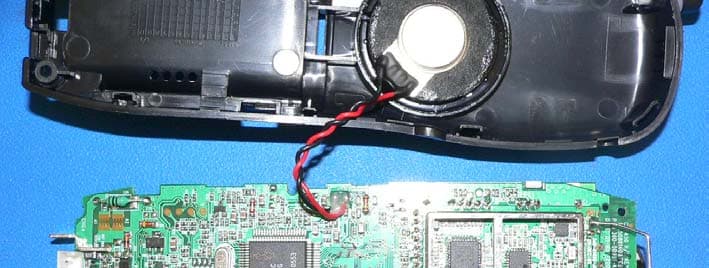
NC8CT5450
Aug 14, 20065.8GHz Cordless Phone
Equipment Class
DSS - Part 15 Spread Spectrum Transmitter
NC8MD2400
Jun 11, 20062.4Gz Cordless Phone
Equipment Class
DSS - Part 15 Spread Spectrum Transmitter
NC8KX-TG2120
May 24, 20062.4GHz/900MHz Analog Cordless phone w/ CID (Base)
Equipment Class
DXT - Part 15 Low Power Transceiver, Rx Verified