NCP700671BNon Broadcast Transmitter
Midland Radio Corporation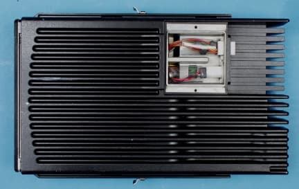
Click to zoom
Application Details
- Equipment Class
- TNB - Licensed Non-Broadcast Station Transmitter
- Date of Grant
- Feb 02, 2000
- Application Purpose
- Original Equipment
- Date of Application
- Nov 01, 1999
- Equipment Note
- Non Broadcast Transmitter
- Frequency Range
- 36.00000000 - 42.00000000
- Company
- Midland Radio Corporation
- Country
- United States
Documents & Files
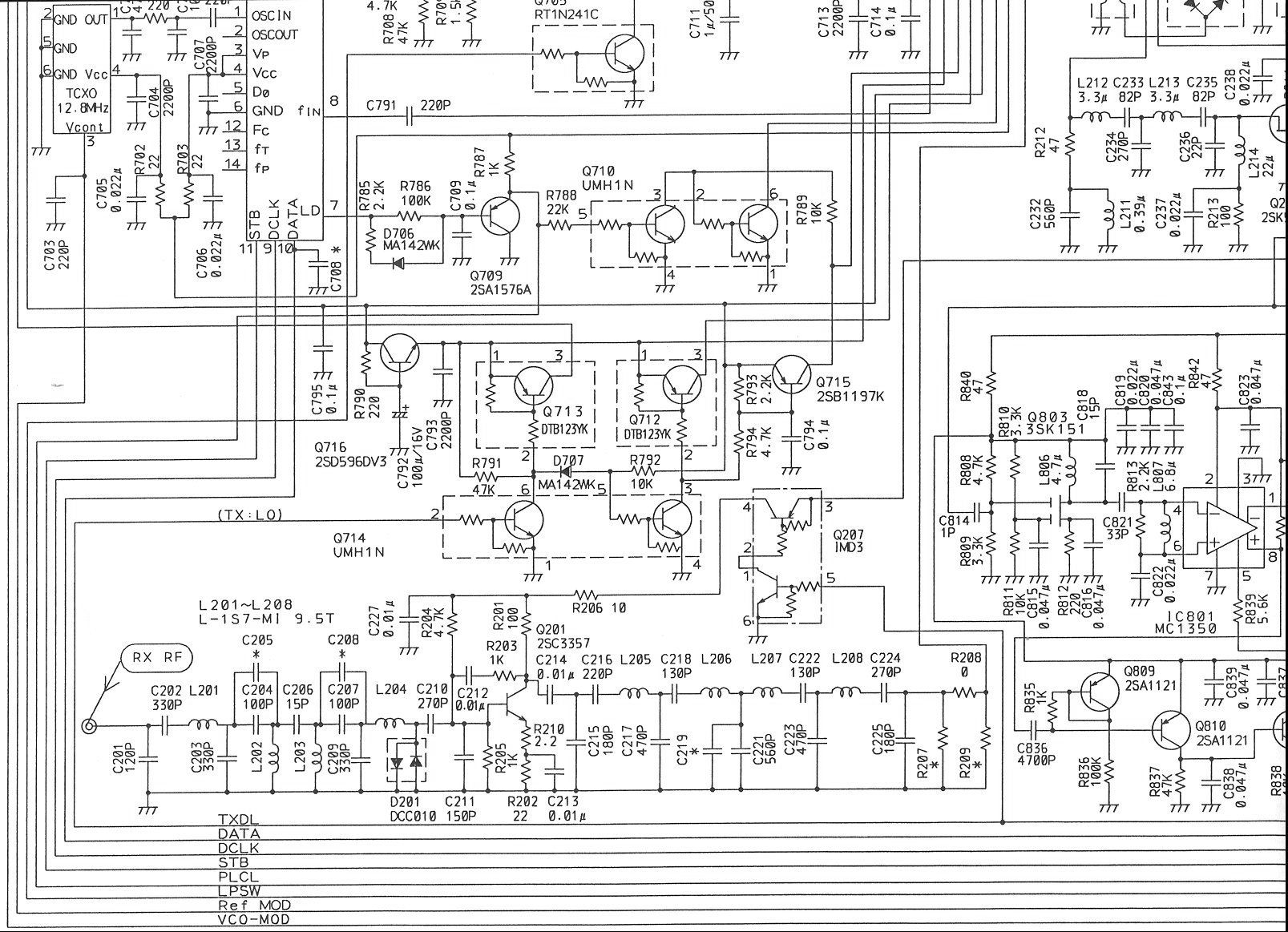
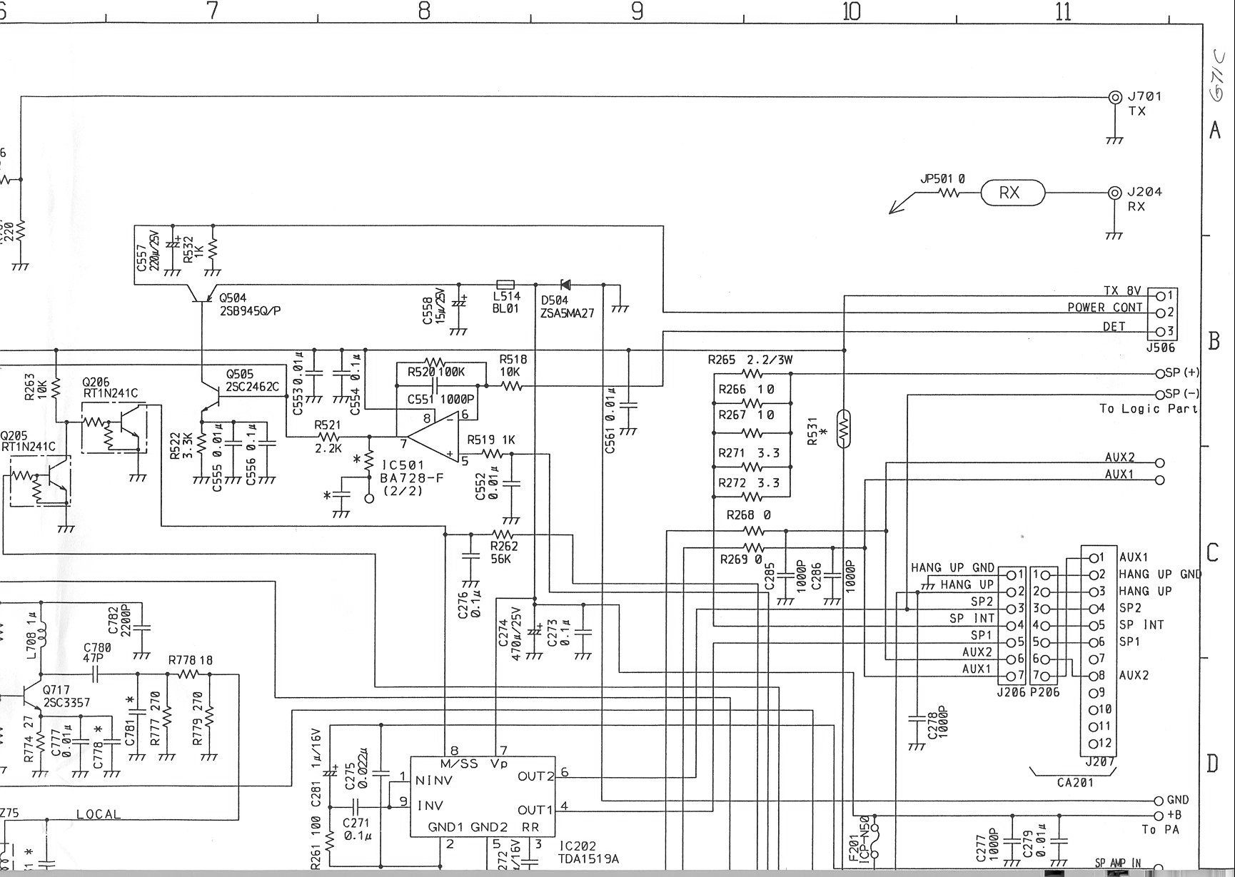
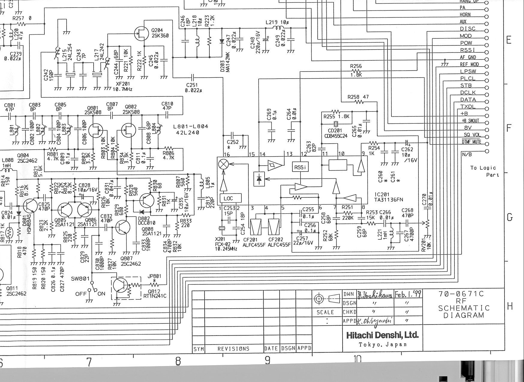
Document Text
Text extracted from the exhibit documents filed with the FCC. Open a document above to read the original.
External Photos
FRONT VIEW SIDE VIEW 1 SIDE VIEW 2 BOTTOM VIEW TOP VIEW REAR VIEW
Internal Photos
COMPONENT WITH SHIELDS COMPONENT WITHOUT SHIELDS EXCITER,TRACK SIDE PA, TRACK SIDE CONTROL I/F CONTROL HEAD CONTROL, REAR CONTROL, TRACK CONTROL, COMPONENT CONTROL, COMPONENT 2 CONTROL CASE
Test Report
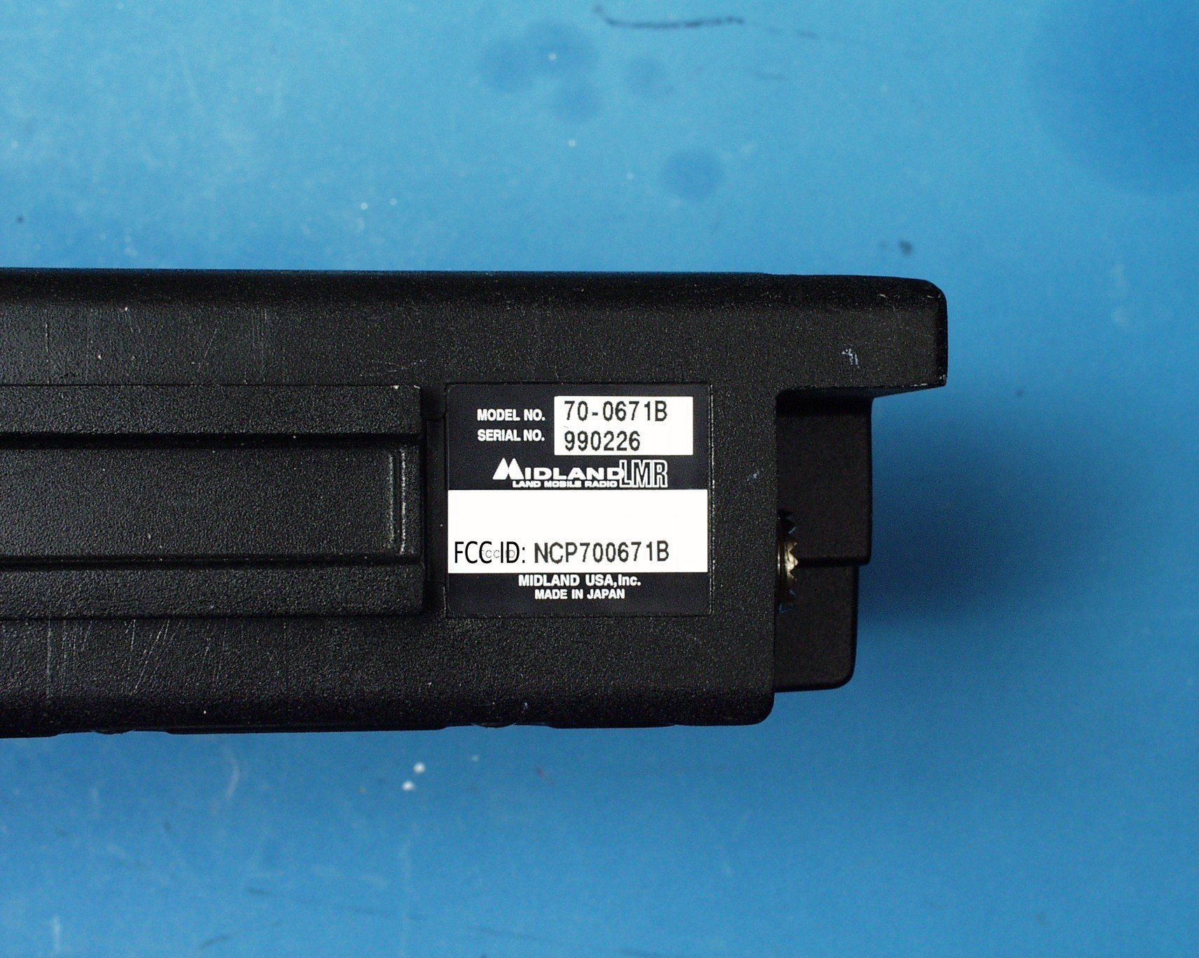
ENGINEERING STATEMENT For Type Certification of MIDLAND USA INC. Model No: 70-0671B FCC ID: NCP700671B I am an Electronics Engineer, a principal in the firm of Hyak Laboratories, Inc., Springfield, Virginia. My education and experience are a matter of record with the Federal Communications Commission. Hyak Laboratories, Inc. has been authorized by Midland USA Inc. to make type certification measurements on the 70-0671B transceiver. These tests made by me or under my supervision in our Springfield laboratory. Test data and documentation required by the FCC for Type Certification are included in this report. The data verifies that the above mentioned transceiver meets FCC requirements and Type Certification is requested. ______________________________ Rowland S. Johnson Dated: October 28, 1999 A. INTRODUCTION 2 The following data are submitted in connection with this request for Type Certification of the 70-0671B transceiver in accordance with Part 2, Subpart J of the FCC Rules. The 70-0671B is a VHF, frequency modulated transceiver intended for 25 kHz land mobile applications in the 36 to 42 MHz band. It operates from a 13.8 vehicle supply. Nominal output power rating is 110 watts. The transceiver is electrically identical, except for operating range, to the 70-0671C for which Type Certification is pending. B. RF POWER OUTPUT (Paragraph 2.985(a) of the Rules) RF power output was measured with a Bird 4421 RF power meter and a Bird 8325 attenuator as a 50 ohm dummy load. Maximum power measured was 110 watts. C. MODULATION CHARACTERISTICS Occupied_Bandwidth (Paragraphs 2.989(c), 90.209(b)(4) and 90.210(d)of the Rules) Figure 1 is a plot of the sideband envelope of the transmitter for 110 watt output taken with an Advantest R3361A spectrum analyzer. Modulation corresponded to conditions of 2.989(c)(1) and consisted of 2500 Hz tone at an input level 16 dB greater than that necessary to produce 50% modulation at 2640 Hz, the frequency of maximum response. Measured modulation under these conditions was 4.0 kHz. The plot has unmodulated carrier as 0 dBm reference. The plots are within the limits imposed by Paragraph 90.210(b) for frequency modulation. The horizontal scale (frequency) is 10 kHz per division and the vertical scale (amplitude) is a logarithmic presentation equal to 10 dB per division. FIGURE 1 3 OCCUPIED BANDWIDTH ATTENUATION IN dB BELOW MEAN OUTPUT POWER Required On any frequency more than 50% up to and including 100% of the 25 authorized bandwidth, 20 kHz (10-20 kHz) On any frequency more than 100%, up to and including 250% of the 35 authorized bandwidth (20-50 kHz) On any frequency removed from the assigned frequency by more 43+10LogP = 63 than 250% of the authorized (P = 110 W) bandwidth (over 50 kHz) OCCUPIED BANDWIDTH FCC ID: NCP700671B FIGURE 1 C. MODULATION CHARACTERISTICS (Continued) The plot is within the limits imposed by Paragraph 90.210(b) for frequency modulation. The horizontal scale (frequency) is 10 kHz per division and the vertical scale (amplitude) is a logarithmic presentation equal to 10 dB per division. 4 D. SPURIOUS EMISSIONS AT THE ANTENNA TERMINALS (Paragraph 2.991 of the Rules) The 70-0671B transmitter was tested for spurious emissions at the antenna terminals while the equipment was modulated with a 2500 Hz signal, 16 dB above minimum input signal for 50% (2.5 kHz deviation) modulation at 2640 Hz, the frequency of highest sensitivity. Measurements were made with Tektronix 494P spectrum analyzer coupled to the transmitter output terminal through a Bird 8325 power attenuator. A notch filter was used to attenuate the carrier. During the tests, the transmitter was terminated in the 50 ohm attenuator. Power was monitored on a Bird 43 Thru-Line wattmeter; dc supply was 13.8 volts throughout the tests. Spurious emissions were measured at 110 watts output throughout the RF spectrum from 12 (lowest frequency generated in the transmitter is 12.8 MHz) to the tenth harmonic of the carrier. Any emissions that were between the required attenuation and the noise floor of the spectrum analyzer were recorded. Data are shown in Table 1. E. DESCRIPTION OF RADIATED SPURIOUS MEASUREMENT FACILITIES A description of the Hyak Laboratories' radiation test facility is a matter of record with the FCC. The facility meets ANSI 63.4-1992 and was accepted for radiation measurements from 25 to 1000 MHz on October 1, 1976 and is currently listed as an accepted site. TABLE 1 TRANSMITTER CONDUCTED SPURIOUS 39.000, 13.8 Vdc Input, 110 W Spurious dB Below Frequency Carrier ___MHz___ Reference 78.000 73 117.000 85 156.000 87 5 195.000 91 234.000 72 273.000 89 312.000 97 351.000 >100 390.000 100 Required: 43+10Log(P) 63 All other emissions from 12 MHz to the tenth harmonic were 20 dB or more below FCC limit. *Reference data only, more than 20 dB below FCC limit. NOTE: Carrier notch filter used to increase dynamic range. F. FIELD STRENGTH MEASUREMENTS OF SPURIOUS RADIATION Field intensity measurements of radiated spurious emissions from the Midland 70-0671B were made with a Tektronix 494P spectrum analyzer using Singer DM-105A calibrated dipole antennas. The transmitter and dummy load were located in an open field 3 meters from the test antenna. Supply voltage was a power supply with a terminal voltage under load of 13.8 Vdc. Output power was 110 watts at 46.000 MHz operating frequency. The transmitter and test antennas were arranged to maximize pickup. Both vertical and horizontal test antennae polarization were employed. Reference level for the spurious radiation was taken as an ideal dipole excited by 110 watts, the output power of the transmitter according to the following relationship:* E = (49.2P t ) 1/2 R 6 where E = electric-field intensity in volts/meter P t = transmitter power in watts R = distance in meters for this case E = (49.2x110.0) 1/2 = 24.5 V/m 3 Since the spectrum analyzer is calibrated in decibels above one milliwatt (dBm), a conversion, for convenience, was made from dBu to…
Text truncated - open the document above for the full version.
Contact Information
Applicant
Jeff Brame(Director of Engineering)
Technical Contact
Hyak Laboratories, Inc.Rowland S Johnson
[email protected](703) 451-1188
7011 Calamo St., Suite 107 · Springfield, Virginia · United States
Non-Technical Contact
Hyak Laboratories, Inc.Georgia Hall
[email protected](703) 451-1188
Test Firm
Hyak Laboratories, Inc.Rowland Johnson
703-451-1188
Technical Specifications
| # | Rule Parts | Frequency Range | Power Output | Emission | Tolerance |
|---|---|---|---|---|---|
| 1 | 90 | 36 MHz - 42 MHz | 110 W | 16k0F3E | 0.0020000000 % |
Other Applications from Midland Radio Corporation
NCP700671C
Jan 31, 2000Non-Broadcast Transmitter
Equipment Class
TNB - Licensed Non-Broadcast Station Transmitter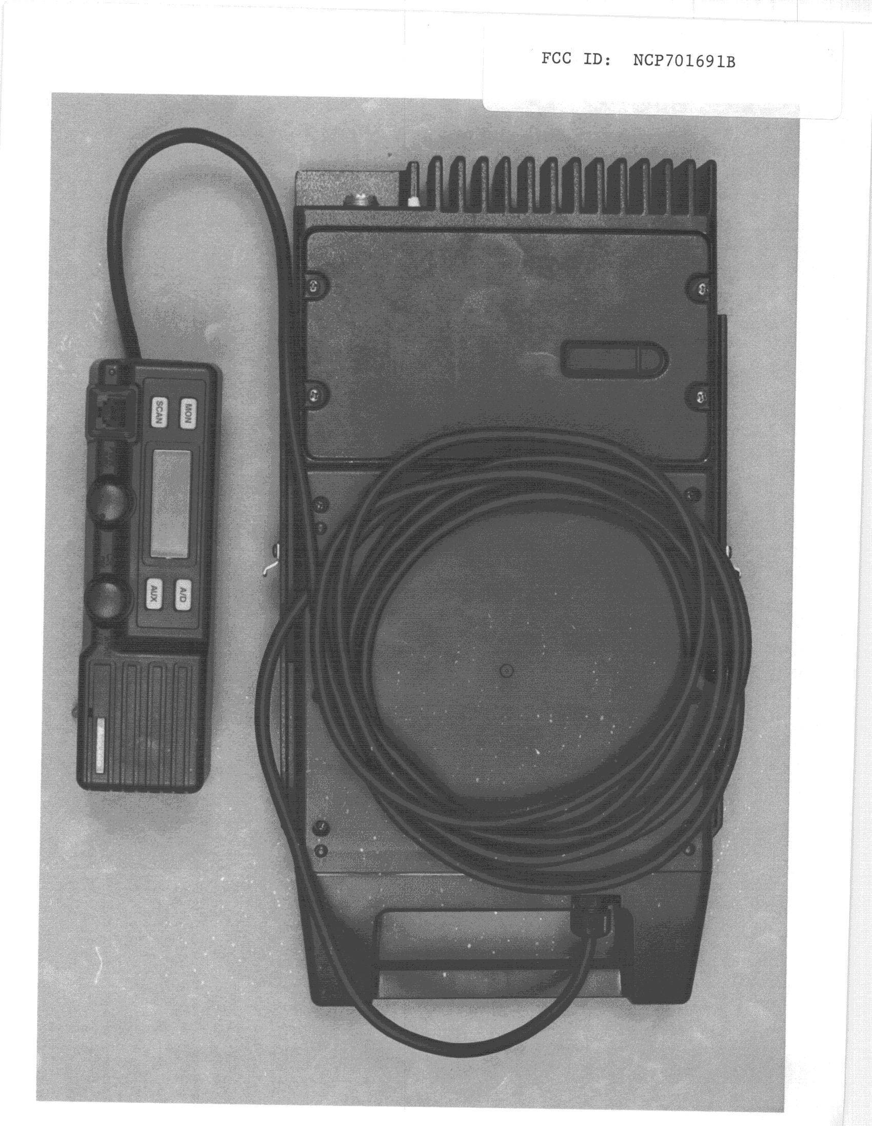
NCP701691B
Apr 14, 1999Mobile
Equipment Class
TNB - Licensed Non-Broadcast Station TransmitterNCP701541B
Aug 13, 1998TNB - Licensed Non-Broadcast Station Transmitter
Equipment Class
TNB - Licensed Non-Broadcast Station TransmitterNCP701341B
Mar 01, 1998Mobile
Equipment Class
TNB - Licensed Non-Broadcast Station TransmitterNCP701527B
Sep 29, 1997Single Channel Mode
Equipment Class
TNB - Licensed Non-Broadcast Station Transmitter