NEJNT2Cordless Pen
A T Cross Company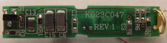
Click to zoom
Application Details
- Equipment Class
- DCD - Part 15 Low Power Transmitter Below 1705 kHz
- Date of Grant
- Dec 09, 2002
- Application Purpose
- Original Equipment
- Date of Application
- Dec 09, 2002
- Equipment Note
- Cordless Pen
- Frequency Range
- 0.41500000 - 0.49400000
- Company
- A T Cross Company
- Country
- United States
Documents & Files
Document Text
Text extracted from the exhibit documents filed with the FCC. Open a document above to read the original.
Users Manual
PPS1, Revsion 1 6 September, 2002 Page 1/8 DIGITAL TABLET WRITING INSTRUMENT PRODUCT AND TEST SPECIFICATION Document No.: PPS-1 Revision: 1 Date: 6 September, 2002 A.T. Cross Company One Albion Road Lincoln, Rhode Island, USA 02865 Author: Robert S. Douglas Performance and test specification for Cross Digital Tablet Writing Instruments PPS1, Revsion 1, 6 September, 2002 Page 2/8 1.0 Scope 1.1 This document specifies the operational, qualification, and acceptance requirements of A. T. Cross digital writing instruments. This document, when specified on the applicable drawing, forms part of the drawing. 1.2 Paragraphs in this document specifying operational or test requirements for components that do not exist in the final product are to be disregarded. 1.3 Where there is a conflict between a specification in this document and an individual unit drawing, the drawing requirement shall be governing. 2.0 Applicable Documents 2.1 A. T. Cross Specifications 2.1.1 Quality Matrix 2.1.2 TP088 - Cap Pull Off Inspection Procedure 2.1.3 TP114 - Heat/Freeze Test 2.1.4 TP115 - Qualification/Evaluation Drop Test 2.1.5 TP139 - Clip Cycle Preload and Life Cycle Testing 2.1.6 TP143 - Heat Aging Test 2.1.7 TP156 - Ship, Drop, and Vibration Tests 2.1.8 TP158 - Dashboard Test 2.1.9 TP190 - Digital Tablet Pen Tip Switch Cycling Test 2.1.10 TP191 - Digital Tablet Pen Side Switch Cycling Test 2.1.11 TP192 - Digital Tablet Pen Side Switch Functional Test 2.1.12 TP193 - Digital Tablet Pen Refill Insertion/Removal Test 2.1.13 TP194 - Digital Tablet Pen Maximum Tip Switch Travel Test 2.1.14 TP195 - Digital Tablet Pen Current Consumption Test 2.1.15 TP196 - Digital Tablet Pen Functional Test 2.1.16 TP197 - Digital Tablet Pen Tip Switch Actuation Force Test 2.1.17 TP198 - Digital Tablet Pen Barrel Torque Test 2.2 Compliance Specifications 2.2.1 CISPR Publication 22 - Limits and Methods of Measurement of Radio Interference Characteristics of Information Technology Equipment 2.2.2 IEC 61000-4-2 - Electrostatic Discharge Immunity Test 2.2.3 IEC 61000-4-3 - Radiated, RF, EMF Electromagnetic Fields Immunity Test 2.2.4 Title 47 CFR, Part 15, Subpart B - FCC, Radio Frequency Devices, Unintentional Radiators 2.2.5 EN 60950 2.2.6 UL 60950 - Underwriter's Laboratories Standard for Safety of Information Technology Equipment 2.2.7 VCCI 2.3 Other 2.3.1 ANSI/NEDA 25A 2.3.2 IEC LR61 2.3.3 NSTA - National Safe Transit Association Pre Shipment Test Procedures 3.0 Specifications 3.1 Environmental - The pen shall be capable of operation under the following operating conditions and sustain no damage after exposure to the non-operating conditions. The pen shall be capable of normal operation after removal from exposure to the non-operating conditions. 3.1.1 Temperature 3.1.1.1 Operating 0°C to +50°C (+32°F to +122°F) 3.1.1.2 Non-Operating (continuous) -20°C to +60°C (-4°F to +140°F) PPS1, Revsion 1, 6 September, 2002 Page 3/8 3.1.1.3 Extreme (10 minutes) 99°C (210°F) 3.1.2 Thermal Cycling (non-operating) - The unit shall be capable of cycling between the extremes of the non-operating temperatures of paragraph 3.1.1.2. 3.1.3 Relative Humidity (Non-Condensing) 3.1.3.1 Operating 5% to 95% RH 3.1.3.2 Non-Operating 5% to 95% RH 3.1.4 Altitude 3.1.4.1 Operating <3657m above MSL (12,000 ft.) 3.1.4.2 Non-Operating <12,000 m above MSL (39,360 ft.) 3.1.5 Shock 3.1.5.1 Unit Drop Test - The pen shall operate as specified after dropping from 91.5 cm (36 in.) and landing in any orientation on to a linoleum- covered concrete floor. This requirement does not apply to the stylus or inking refill but one must be installed for proper testing. 3.1.5.2 Packaging Drop Test - When properly packaged, the pen shall operate after being dropped from a height of 152.5 cm (60 in.) and landing on any package edge or vertex on a concrete floor. 3.1.6 Vibration (non-operating) 3.1.6.1 Random 6.1G, rms 3.1.6.2 Sine 1.0G, peak, 5Hz to 500Hz 3.1.6.3 Packaged Packaged product shall be capable of withstanding the vibration set fort in the National Safe Transit Association Pre Shipment Test Procedures Project 1A, section B, Part 1. 3.1.7 Electromagnetic Interference Emissions - The unit must comply with the emissions requirements of the following: 3.1.7.1 IEC CISPR Publication 22 for a Class B device 3.1.7.2 FCC Rules and Regulations, Title 47, Part 15, Subpart B for a Class B device. 3.1.7.3 VCCI Class B ITE 3.1.8 Electromagnetic Interference Immunity - The unit must comply with the immunity requirements of IEC 61000-4-3 3.1.9 Electrostatic Discharge Immunity 3.1.9.1 Contact Discharge - The unit shall be capable of accepting an electrostatic contact discharge of ± 15kV with no user intervention required to resume proper functioning. 3.1.9.2 Air Discharge - The unit shall be capable of accepting an electrostatic air discharge of ± 15kV with no user intervention required to resume proper functioning. 3.2 Mechanical 3.2.1 Tip Switch - The device contains a tip switch that is activated when the pen tip, inking or non-inking user-replaceable refill, is depressed. 3.2.1.1 Normally Closed - The switch is normally closed when the tip is not depressed. 3.2.1.2 Actuation Force and Travel - The forces to activate the switch and the minimum activation travel and maximum travel of the switch are specified on the applicable drawing. 3.2.1.3 Cycle life - The tip switch shall be capable of 10 million cycles from the normally closed position to full actuation at a maximum load of 125 g f (4.4 oz). 3.2.2 Single Action Side Switch - The device may contain a side switch that is actuated independently of the tip switch by a user action. 3.2.2.1 Momentary Switch - The side switch is a normally open momentary on/off switch with tactile feel. 3.2.2.2 Actuation Force - The side switch shall be activated by application of 160 ± 60 g f (5.6 ± 2.1 oz). PPS1, Revsion 1, 6 September, 2002 Page 4/8 3.2.2.3 Cycle life - The side switch shall be capable of 500,000 cycles of 0 g f to 220 g f ( 0 oz to 7.7 oz)…
Text truncated - open the document above for the full version.
Users Manual
FCC STATEMENT Compliance This device complies with part 15 of the FCC Rules. Operation is subject to the following two conditions: (1) This device may not cause harmful interference, and (2) this device must accept any interference received, including interference that may cause undesired operation. OEM/End User Information Any modifications or changes to this intentional radiator (pen) by either the end user or OEM that is not expressly approved by the party responsible for compliance (FinePoint Innovations, Inc.) could void the user’s authority to operate the pen. ATTENTION TO INSTALLER/OEM The two above statements are required by the FCC 47CFR 15.19 and 15.21 to be put in the final products manual along with the statement in FCC 47CFR 15.105 (Information to the user). It is up to the Installer/OEM to fulfill this requirement or the final product cannot be placed on the market.
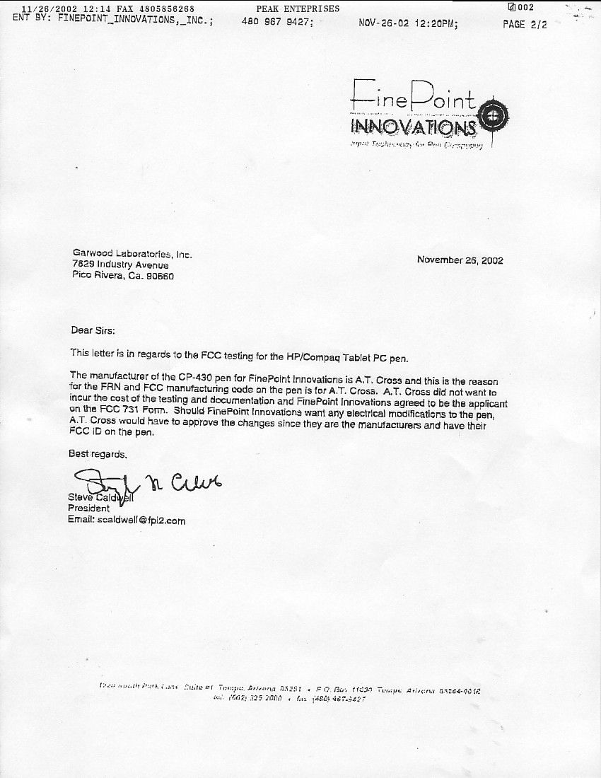
Cover Letter(s)
Request for Confidentiality 11/26/02 Garwood Laboratories, Inc. 7829 Industry Ave Pico Rivera, CA 90660-4305 Applicant: FinePoint Innovations FCC ID: NEJNT2 Please withhold the following items from public viewing on behalf of the applicant, FinePoint Innovations. 1. Schematics 2. Block Diagram The items listed above contain technical information, which the applicant, FinePoint Innovations, deems to be trade secrets and proprietary. If made public, the information might be used to the disadvantage of the applicant in the market place. Sincerely, Arnie Tapia Authorized Agent Garwood Laboratories, Inc.
External Photos
External Picture
ID Label/Location Info
FCC ID Label and Location FCC ID NEJNT2
Internal Photos
INTERNAL PICTURES Pen disassembled Top Side Bottom Side
Operational Description
PRELIMINARY FinePoint Innovations Company Confidential 40337-0056 Rev Y1 Master Disk #nnnn Software: MSW2000 Level 4 Document File Name: Joey_Engineering_Spec.doc © 2002 FinePoint Innovations 1220 S. Park Lane Suite 1, Tempe, Az 85281 Tel: 602-325-2080 Fax: 480-967-9427 FINEPOINT INNOVATIONS, INC. E NGINEERING SPECIFICATION ”H OUSTON” 10.4-INCH CUSTOM P EN INPUT SUBSYSTEM FPI Project Name: Houston Originator David Frost, Lead Project Engineer Date 11 July 2002 (Signature) Approved by Lynn Rockwell, Director of Engineering Date (Signature) This document contains information that is proprietary and is the sole and exclusive property of FinePoint Innovations, Incorporated. It is to be considered confidential by all to whom it is furnished and shall not be duplicated without the express written permission of FinePoint Innovations Incorporated. Document disposal procedure: Shred PRELIMINARY FinePoint Innovations, Company Confidential P/N: 40337-0056 Rev: Y1 Page 2 of 22 Document History Revision Description of Changes DCN No. Date X Initial Release nnnnn 11 Jul 2002 Y Updated to reflect PV Build Documentation 19 Aug 2002 Y1 Update to eliminate unspecified and erroneous data. 91882 18 Nov 2002 Note: DCN stands for Document Change Notice PRELIMINARY FinePoint Innovations, Company Confidential P/N: 40337-0056 Rev: Y1 Page 3 of 22 SPECIFICATION PEN INPUT SUBSYSTEM FOR HOUSTON TABLE OF CONTENTS 1.0 INTRODUCTION ...................................................................................................................................... 4 1.1 Scope................................................................................................................................ 4 1.2 Pen System Controller (PSC) & System Operation .................................................... 4 1.3 Pen System Standard Configuration Diagram ............................................................ 5 1.4 Custom Configuration Description............................................................................... 5 2.0 PEN SPECIFICATION.............................................................................................................................. 7 2.1 Pen - Physical Specification ........................................................................................... 7 2.2 Pen - Mechanical Performance Specification .............................................................. 7 2.3 Pen - Electrical Performance Specification.................................................................. 7 2.4 Pen - Environmental Specification................................................................................ 8 3.0 SENSOR GRID AND PSC ELECTRONICS SPECIFICATION........................................................... 9 3.1 Physical Specification..................................................................................................... 9 3.2 Electrical Specification ................................................................................................ 10 3.3 Environmental Specification ....................................................................................... 15 4.0 PEN SYSTEM PERFORMANCE SPECIFICATION .......................................................................... 16 4.1 System Performance..................................................................................................... 16 4.2 Diagnostics ..................................................................................................................... 17 5.0 MISCELLANEOUS REQUIREMENTS ................................................................................................. 18 5.1 Integration Requirements............................................................................................. 18 5.2 Shipping Requirements................................................................................................. 18 APPENDIX: PSC Download Command Definitions ............................................................................... 19 PRELIMINARY FinePoint Innovations, Company Confidential P/N: 40337-0056 Rev: Y1 Page 4 of 22 1.0 INTRODUCTION The FinePoint Innovations, Inc (FPI) “Houston” configuration of the Pen Input System is designed specifically for use as a drop-in digitizer for the Toshiba LTM10C321K (“Kangaroo”) 10.4 inch LCD. It is a high-performance magnetic-component OEM tablet/digitizer consisting of two major components: a cordless battery-powered pen, a digitizer assembly. The digitizer assembly consists of a custom sensor grid and a pen system controller connected together by a flexible cable and adhesive. The sensor grid board mounts onto the back of the above-mentioned Toshiba LCD. It is specifically designed to slide between the LCD assembly and the LCD control card attached to the rear of it, and into the thin digitizer mounting “pocket”. The FPI Pen Input System is designed for high-speed handwriting input and low-power usage. It utilizes a unique and proprietary position resolving system that combines both high accuracy and high-slew speeds for handwriting and character recognition applications. It can be used in a variety of pen based computer applications for writing directly on an LCD with a pen. The sensor grid assembly acts as a multiple wire antenna, and senses the electromagnetic signal from the pen through the LCD. The PSC is the receiving, processing and control element of the pen system. The PSC provides the physical and logical interface from the Pen Input System to the pen-based computer through a serial interface. This particular design has been customized to include additional active area for several button or menu decode areas on one edge and optional LED drive for each of these areas. The LEDs and menu sensor area are controlled and decoded via the command interface and output format respectively. Therefore, custom functions are decoded and controlled by the host system driver. 1.1 Scope This document includes a tech…
Text truncated - open the document above for the full version.
Test Report
1 of 21 FCC TEST REPORT for FINEPOINT INNOVATIONS INC. C ORDLESS PEN Model: ARWOOD LABORATORIES, INC. G Your Most Trusted Name in Testing Since 1954. Date: October 3, 2002 EUT: Cordless Pen Page 2 of 21 GARWOOD LABORATORIES, INC. TESTING AND ENGINEERING SERVICES FCC TEST REPORT Certification for FCC Part 15 Subpart C §15.209 Report for: FINEPOINT INNOVATIONS INC. C ORDLESS PEN Model: Prepared For: Finepoint Innovations Inc. 1220 S. Park Lane, Suite 1 Tempe, AZ 85281 Prepared By: Garwood Laboratories, Inc 7829 Industry Avenue Pico Rivera, CA 90660 Issued: October 3, 2002 GARWOOD LABORATORIES, INC. 7829 Industry Avenue, Pico Rivera, CA 90660 Report No: FR25249-E FCC TEST REPORT FOR FINEPOINT INNOVATIONS INC. Date: October 3, 2002 EUT: Cordless Pen Page 3 of 21 Testing Services Since 1954 ® “EXCELLENCE BUILT ON INTEGRITY” RESPONSIBLE SIGNATURES This report is intended for the use by the organization to whom it is addressed, and will not be made available to any other parties without the expressed written consent of the aforementioned organization. This report shall not be reproduced, except in full, without the written approval of Garwood Laboratories, Inc. WRITTEN BY: REVIEWED BY: REVIEWED BY: Arnulfo Tapia EMC Test Engineer William Flower Quality Assurance Manager Tony Masone EMC Manager DOCUMENT HISTORY Revision Issue Date Affected Page(s) Description Of Modifications Revised By Approved By N/C Initial release GARWOOD LABORATORIES, INC. 7829 Industry Avenue, Pico Rivera, CA 90660 Report No: FR25249-E FCC TEST REPORT FOR FINEPOINT INNOVATIONS INC. Date: October 3, 2002 EUT: Cordless Pen Page 4 of 21 Testing Services Since 1954 ® “EXCELLENCE BUILT ON INTEGRITY” CLIENT INFORMATION Purchase Order EUT Arrival Date COD August 22, 2002 Company Name Address City, State Zip Finepoint Innovations Inc. 1220 S. Park Lane, Suite 1 Tempe AZ 85281 Contact Name Phone Fax Stephen Caldwell 602-325-2080 480-967-9427 GARWOOD INFORMATION EMC Test Laboratory Address City, State, Zip Code Phone Fax Web Site Garwood Laboratories, Inc. 7829 Industry Avenue Pico Rivera, CA 90660 (562) 949-2727 (562) 949-8757 www.garwoodtestlabs.com Contact Name Title Tony Masone EMC Manager Test Personnel Test Dates Arnie Tapia – EMC Test Engineer September 6, 2002 GARWOOD LABORATORIES, INC. 7829 Industry Avenue, Pico Rivera, CA 90660 Report No: FR25249-E FCC TEST REPORT FOR FINEPOINT INNOVATIONS INC. Date: October 3, 2002 EUT: Cordless Pen Page 5 of 21 Testing Services Since 1954 ® “EXCELLENCE BUILT ON INTEGRITY” ACCREDITATIONS: The Open Area Test Site (OATS) and measurement facilities used to collect the test data are located at Garwood Laboratories, Incorporated test facility in Pico Rivera, California. This facility has been fully described in a report submitted to the FCC and accepted in a letter dated 22 April 2002, Registration Number 534174. The test facility is also recognized, certified, or accredited by the following organizations: This site has been registered and fully described in a report filed with the (FCC) Federal Communications Commission. The acceptance letter from the FCC is maintained in our files. Registration #534174. Date of listing: April 22, 2002. Garwood Laboratories is an authorized test laboratory for the DoC process. Garwood Laboratories, Inc. has been assessed in accordance with ISO 17025 and with ITI's assessment criteria. Based upon this assessment, Technology International (Europe), Ltd. has granted approval for specifications implementing the EU Directive on EMC (89/336/EEC). The scope of the approval was provided on a Schedule of Assessment supplied with a certificate and is available upon request. Certificate #01-051, effective through August 5, 2002, or until the next agreed assessment date (October 11, 2002). Garwood Laboratories, Inc. is authorized, by joint agreement with Korea Electric Testing Institute (KETI), to perform required and necessary South Korean Product Safety and EMC testing (including reports) according to the IEC and CISPR standards. Nmi (Nederlands Meetinstituut) Garwood Laboratories, Inc. has entered into a cooperative agreement with Nmi Certin B.V. of the Netherlands. This is a Notified Body for the RATTE Directive and Maritime Directive as well as a Competent Body for the EMC Directive. GARWOOD LABORATORIES, INC. 7829 Industry Avenue, Pico Rivera, CA 90660 Report No: FR25249-E FCC TEST REPORT FOR FINEPOINT INNOVATIONS INC. Date: October 3, 2002 EUT: Cordless Pen Page 6 of 21 Testing Services Since 1954 ® “EXCELLENCE BUILT ON INTEGRITY” TABLE OF CONTENTS MEASUREMENT / TECHNICAL REPORT SUMMARY ............................................................................ 7 1. GENERAL INFORMATION................................................................................................................... 8 1.1 Product Description ...................................................................................................... 8 1.2 Related Submittal(s)/ Grant(s) ...................................................................................... 8 1.3 Tested System Description ............................................................................................ 8 1.4 Test Methodology .......................................................................................................... 9 2. PRODUCT LABELING........................................................................................................................ 10 2.1 FCC Declaration of Conformity Label ....................................................................... 10 2.2 Location of Label on EUT........................................................................................... 10 2.3 Information to the User............................................................................................... 10 3. SYSTEM TEST CONFIGURATION ..................................................................................................... 11 3.1 Justification ................…
Text truncated - open the document above for the full version.
Test Report
Retest of Cordless Pen Using Loop Antenna Field Strength of the Fundamental: Test Requirement: Field Strength of Emissions from Intentional Radiators (Reference: FCC PT.15, Subpart C, §15.209) Frequency (MHz) Antenna Polarity (V or H) Corrected Reading (dBμV/m) Corrected Reading (μV/m) FCC Limit 1 meter (μV/m) 0.460 N/A 29.2 28.8 1565 Judgment: The EUT, Cordless Pen, complied with the specification requirements. Test Details: Procedure used to determine the limit at 1m: For EUT operating frequency 460kHz: Limit (μV/m) = 2400 / 460 = 5.22μV/m @ 300m Measurements were performed at close-in distances and the limit L2 corresponding to the close-in distance d2 was determined by applying the following relation: L2 = L1 (d1 / d2) Where L1 is the specified limit in μV/m at the distance d1. Close in Limit (μV/m) = 5.22μV/m (300m / 1m) = 1565μV/m @ 1m Close in Limit (dBμV/m) = 63.9dBμV/m @ 1m Test Details (continued): The measurements were now performed with a loop antenna; however, the FCC limits are stated in electric field strength (μV/m). The following procedure was used to obtain the equivalent electric field when measuring with a loop antenna: Wave Impedance Z w : Z w = |E| / |H| In the far field Z w = 377Ω (51.5dBΩ) In the near field if the source is a magnetic source, then the wave impedance Z w can be determined by, Z w = 120* pi * [r o / (√ r o ² + 1)] where, r o = (2*pi*r)/λ r = distance from the source The equivalent electric field can then be determined by, |E| = Z w * |H| or equivalently in dB |E| dB = Z w dB + |H| dB Calculations: r o = (2*pi*1) / 652 = 0.009634 Z w = 120* pi * [0.009634 / (√ 0.009634² + 1)] = 3.63Ω (11.2dB) Loop antenna measurement H(dBμA/m) = S.A (dBμV) + Loop Antenna Factor From the relation: |E| dB = Z w dB + |H| dB E (dBμV/m) = Z w dB + S.A. (dBμV) + Loop Antenna Factor E (dBμV/m) = 11.2 dB + 54.1dBμV + (-36.1dB/m) = 29.2dBμV/m The equivalent electric field strength of the fundamental measured with the loop antenna was 29.2dBμV/m. Reference: Field Strength of Unwanted Emissions: The plot below shows compliance with the Field Strength of Unwanted Emissions requirement. The EUT was tested in 3 different orientations (x, y, z-axis) and there were no detectable unwanted emissions. Band Edge Plot: The Band-edge plot below shows compliance with §15.205 at 495kHz. The device was operating on its highest operating frequency, which was measured at 488kHz.
Test Setup Photos
TEST MEASUREMENT PHOTOS Photo: Radiated Emissions Photo: Radiated Emissions
Contact Information
Applicant
David J Arthur(Engineering V.P.)
Technical Contact
Garwood Laboratories, Inc.Victor Ratinoff
[email protected]562-949-2727
7829 Industry Ave · Pico Rivera, California · United States
Non-Technical Contact
Garwood Laboratories, Inc.Victor Ratinoff
[email protected]562-949-2727
Test Firm
Garwood Laboratories, Inc.Arnie Tapia
Technical Specifications
| # | Rule Parts | Frequency Range | Power Output |
|---|---|---|---|
| 1 | 15C | 0.415 MHz - 0.494 MHz | - |
Other Applications from A T Cross Company
NEJNT1
Jun 05, 1997Tablet Pen
Equipment Class
DCD - Part 15 Low Power Transmitter Below 1705 kHz