NG6POMSMOKESMOKE DETECTOR TRANSMITTER
Advantor Corporation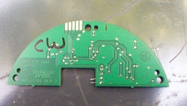
Click to zoom
Application Details
- Equipment Class
- DSC - Part 15 Security/Remote Control Transmitter
- Date of Grant
- Oct 03, 2005
- Application Purpose
- Original Equipment
- Date of Application
- May 19, 1998
- Equipment Note
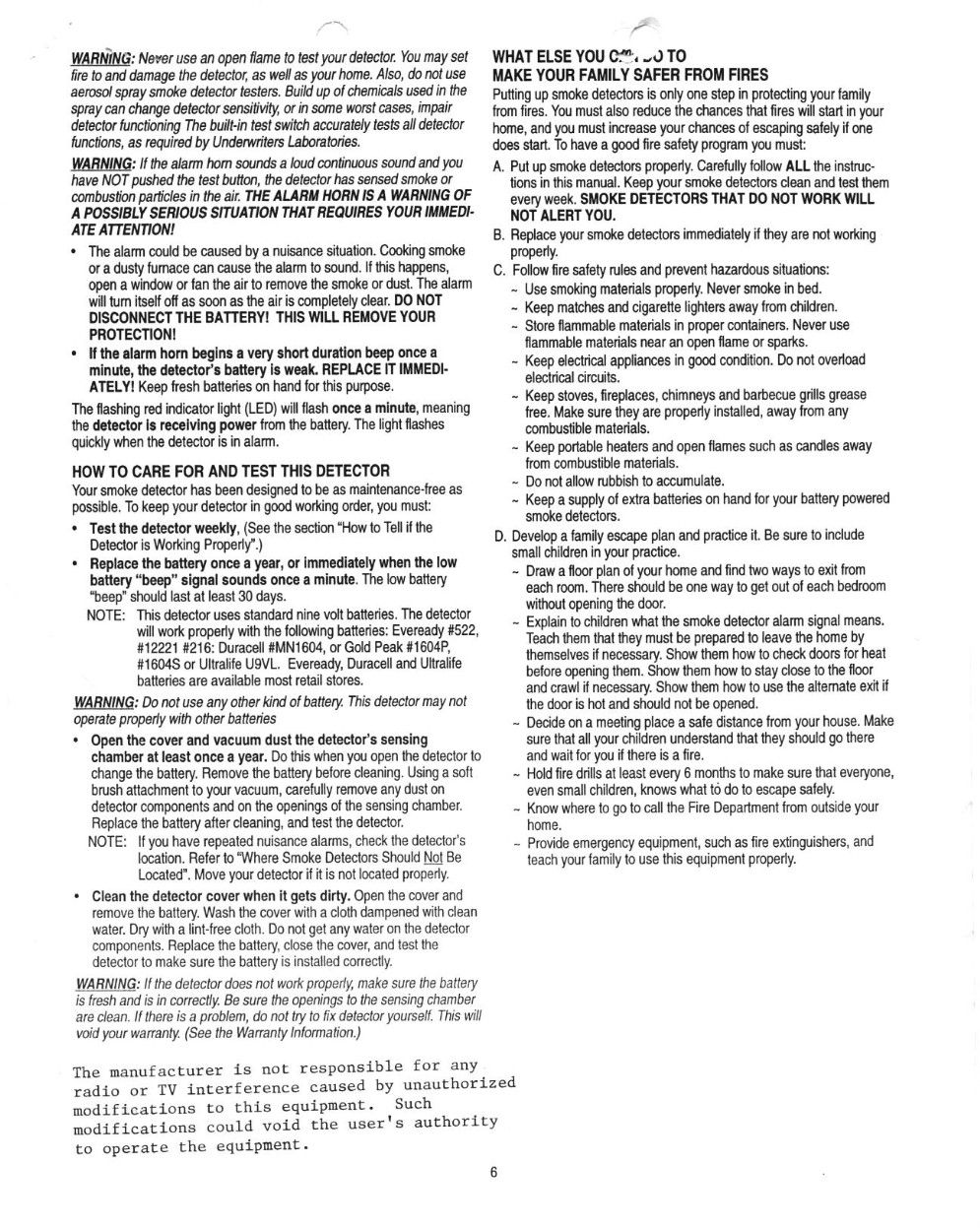
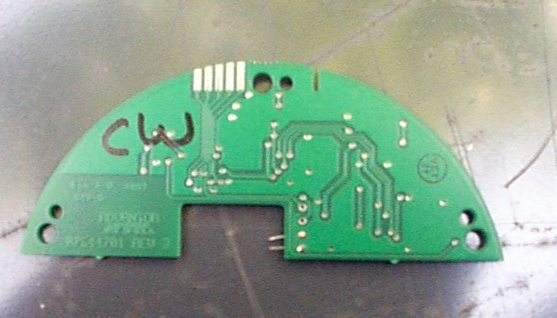
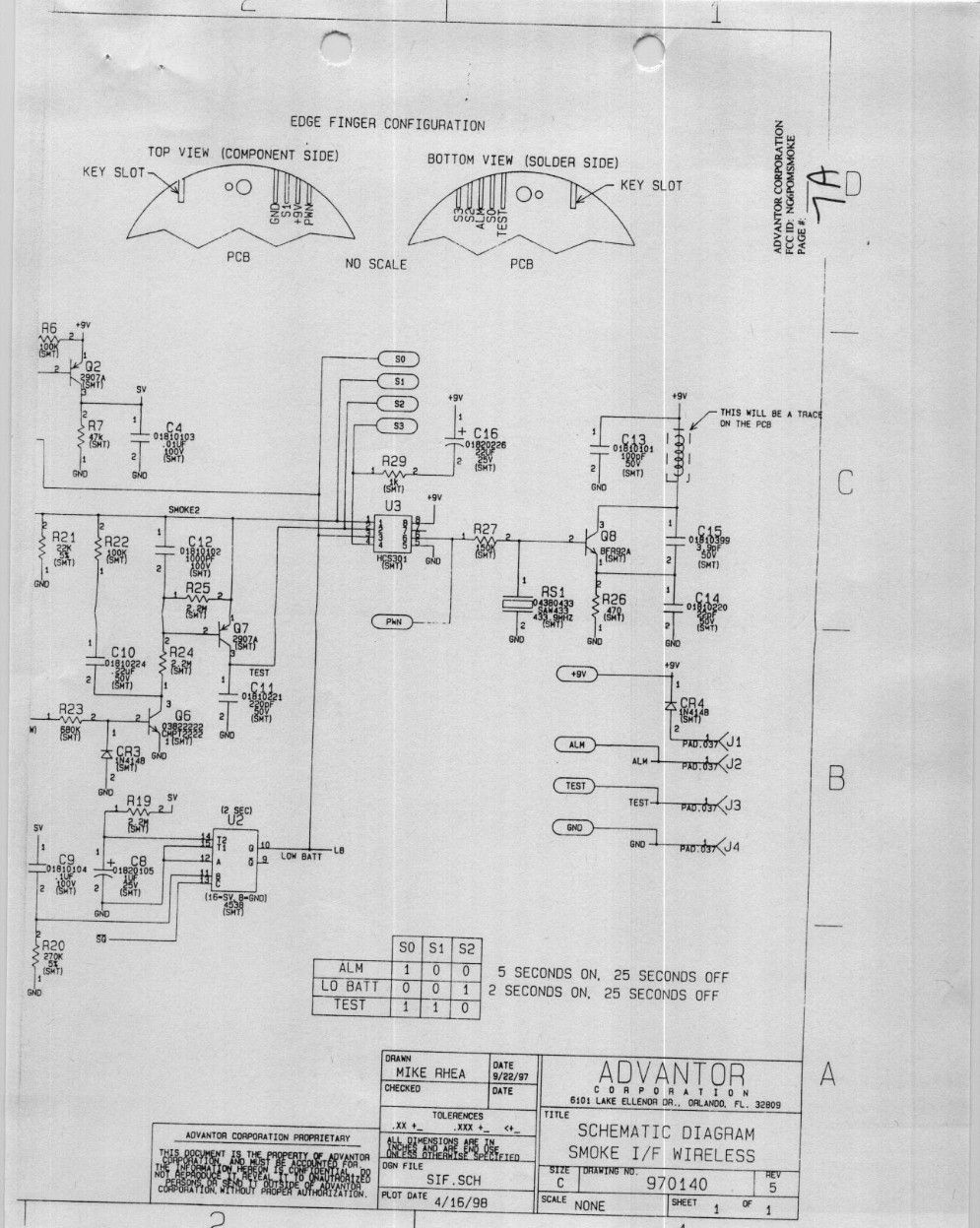
- SMOKE DETECTOR TRANSMITTER
- Frequency Range
- 433.00000000 - 434.00000000
- Company
- Advantor Corporation
- Country
- United States
Documents & Files
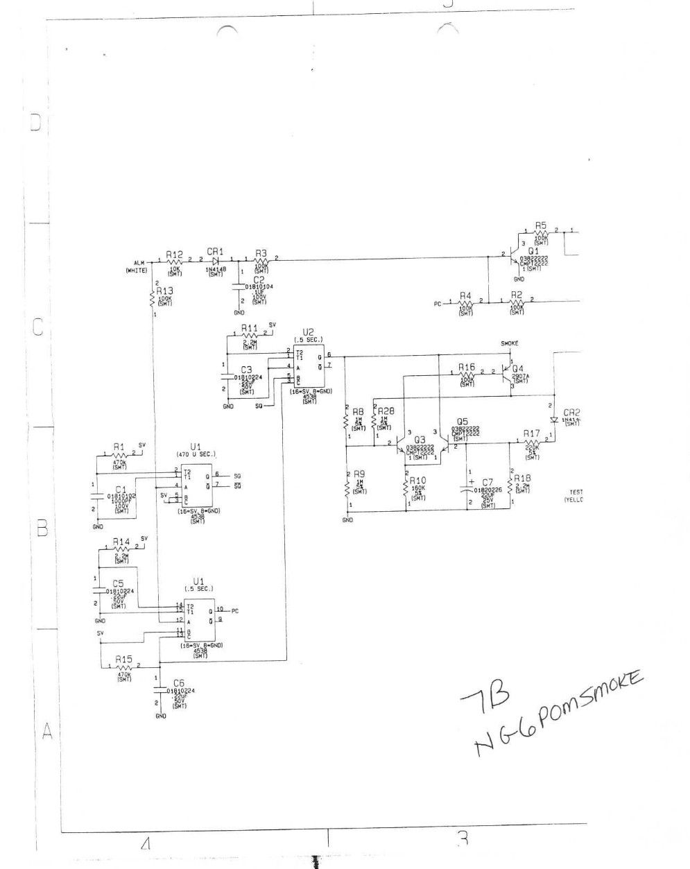
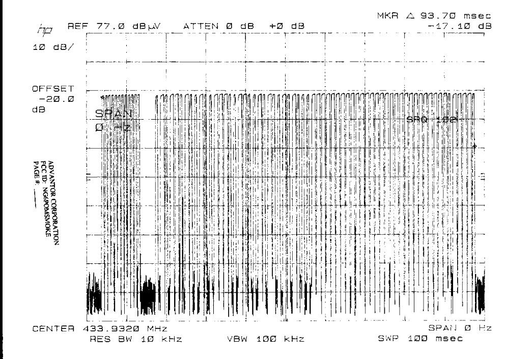
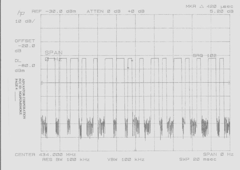
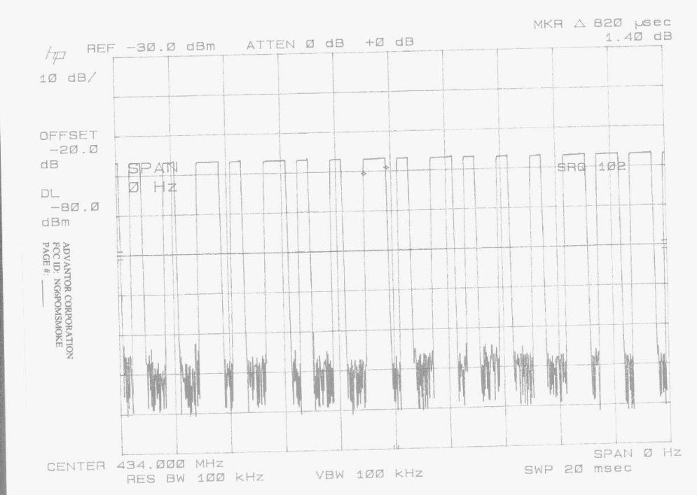
Document Text
Text extracted from the exhibit documents filed with the FCC. Open a document above to read the original.
Test Report
APPLICANT: HANCHANG CORPORATION FCC ID: GH3HD-800 TABLE OF CONTENTS TEST REPORT CONTAINING: PAGE 1........15.214(d) - SECURITY CODING INFORMATION PAGE 2-3......TEST EQUIPMENT LIST AND TEST PROCEDURE AND CIRCUIT DESCRIPTION PAGE 4.........POWER LINE CONDUCTED EMISSIONS PAGE 5.........OCCUPIED BANDWIDTH TEST DATA PAGE 6.........ANTENNA CONDUCTED SPURIOUS EMISSIONS PAGE 7.........RADIATION INTERFERENCE TEST DATA - BASE PAGE 8.........RADIATION INTERFERENCE TEST DATA - HANDSET PAGE 9.........TRANSMITTER POWER DENSITY AND PROCESSING GAIN EXHIBITS: EXHIBIT 1..........CLASS II PERMISSIVE CHANGE REQUEST LETTER EXHIBIT 2..........POWER OF ATTORNEY LETTER EXHIBIT 3A.........SCHEMATIC- HANDSET EXHIBIT 3B.........SCHEMATIC - BASE EXHIBIT 3C.........SCHEMATIC - RF EXHIBIT 4..........BLOCK DIAGRAMS EXHIBIT 5..........FCC ID LABEL SAMPLES EXHIBIT 6..........FCC ID LABEL LOCATION EXHIBIT 7A-7B......LINE CONDUCTED INTERFERENCE TEST DATA EXHIBIT 8A-8F......BANDWIDTH PLOTS EXHIBIT 9A-9F......SPECTRAL DENSITY PLOTS EXHIBIT 10A-10M....USER'S MANUAL EXHIBIT 11.........EXTERNAL FRONT VIEW - BASE AND HANDSET EXHIBIT 12.........EXTERNAL BACK VIEW - BASE AND HANDSET EXHIBIT 13.........INTERNAL COPPER - BASE RF EXHIBIT 14.........INTERNAL COMPONENT - BASE RF EXHIBIT 15.........INTERNAL COPPER - BASE MAIN EXHIBIT 16.........INTERNAL COMPONENT - BASE MAIN EXHIBIT 17.........INTERNAL COMPONENT - HANDSET EXHIBIT 18.........INTERNAL COPPER - HANDSET APPLICANT: HANCHANG CORPORATION FCCID: GH3HD-800 REPORT #: F:\CUS\H\HANCHANG\HAN128B8.RPT PAGE: TABLE OF CONTENTS LIST ® Telephone: (352) 472-5500 (888) 472-2424 Fax: (352) 472-2030 ENGINEERING, INC. E-mail: [email protected] MAY 25, 1998 Federal Communication Commission Authorization and Evaluation Division 7435 Oakland Mills Road Columbia, MD 21046 SUBJECT: FCC ID: GH3HD-800 HANCHANG CORPORATION REFERENCE: REQUEST FOR CLASS II PERMISSIVE CHANGE TO WHOM IT MAY CONCERN: This letter is a request for a Class II Permissive change. The applicant has made modifications to the RF portion of this tele- phone. Attached please find the test data and a revised schematic to reflect these changes. Should you require any further information, please contact me at 1-888-472-2424. Sincerely, S. S. Sanders APPLICANT: HANCHANG CORPORATION FCCID: GH3HD-800 REPORT #: F:\CUS\H\HANCHANG\HAN128B8.RPT EXHIBIT #: 1 TIMCO ENGINEERING, INC. • 25355 WEST NEWBERRY ROAD. • P.O. BOX 370 • NEWBERRY, FL 32669 SECURITY CODING INFORMATION APPLICANT: HANCHANG CORPORATION FCC ID: GH3HD-800 15.214(d) - THIS DEVICE COMPLIES WITH THE SECURITY CODE REQUIRE- MENTS OF 15.214(d)(1)(2) AND (3) BY MEANS OF THE FOLLOWING: THE EPROM IS CAPABLE OF 16 MILLION DIGIT CODING AND THE FACTORY WRITES THE SERIES IN PRODUCTION. THIS MEANS THAT EACH OF 16 MILLION INDIVIDUAL SECURITY CODES ARE REPEATED ONLY ONCE IN ANY CONSECUTIVELY PRODUCED UNIT. APPLICANT: HANCHANG CORPORATION FCCID: GH3HD-800 REPORT #: F:\CUS\H\HANCHANG\HAN128B8.RPT PAGE #: 1 APPLICANT: HANCHANG CORPORATION FCCID : GH3HD-800 TEST EQUIPMENT LIST 1. Spectrum Analyzer: Hewlett Packard 8566B, with preselector HP 85685A, & Quasi-Peak Adapter HP 8565OA, & HP 8449B OPT H02 Cal. 10/1/97 2. Eaton Biconnical Antenna Model 94455-1 20-200 MHz Serial No. 0997 Cal. 9/17/97 3. Electro-Metric Dipole Kit, 20-1000 MHz, Model TDA 25 cal. 5/15/97 4. Electro-Metric Horn 1-18 GHz, Model RGA-180, Cal. 9/24/97 5. Electro-Metric Antennas Model TDS-25-1, TDS-25-2, 9/3/97 6. Electro-Metric Horn 1-18 GHz, Model RGA-180 7. Systron Donner Horn Model No. DBE-520-20 18-26GHz 8. Electro-Metric Line Impedance Stabilization Network Model No. EM-7021, 50uH. 5/21/97 9. Electro-Metric Line Impedance Stabilization Network Model No. EM-7021, 50uH. 5/21/97 10. Peak Power Meter HP 8900C With Peak Power Sensor HP 84811A TEST PROCEDURE GENERAL: This report shall NOT be reproduced except in full without the written approval of TIMCO ENGINEERING, INC. Shielded interface cables were used in all cases except for cables connecting to the telephone line and the power cords. A test program was run which simulated a normal data transmission on a network. POWER LINE CONDUCTED INTERFERENCE: The procedure used was ANSI STAN- DARD C63.4-1992 using a 50uH LISN. Both lines were observed. The bandwidth of the spectrum analyzer was 10kHz with an appro- priate sweep speed. The ambient temperature of the UUT was 78oF with a humidity of 48%. BANDWIDTH 6.0dB: The measurements were made with the spectrum analyz- er's resolution bandwidth(RBW)=100KHz and the video bandwidth(VBW) =300KHz and the span set as shown on plot. POWER OUTPUT: The RF power output was measured at the antenna feed point by removing the permanent antenna and connecting the UUT to a peak power meter, HP Model No. 8900C. ANTENNA CONDUCTED EMISSIONS: The RBW=100KHz, VBW > or = RBW and the spectrum was scanned from 30MHz to the 10th Harmonic of the fundamen- tal. RADIATION INTERFERENCE: The test procedure used was ANSI STANDARD C63.4-1992 using a HEWLETT PACKARD spectrum analyzer with a prese- lector. The bandwidth(RBW) of the spectrum analyzer was 100kHz up to 1GHz and 1.0MHz above 1GHz with an appropriate sweep speed. The VBW above 1.0GHz was = 1.0MHz. The analyzer was calibrated in dB above a microvolt at the output of the antenna. The ambient temperature of the UUT was 78oF with a humidity of 72%. PAGE #: 2 APPLICANT: HANCHANG CORPORATION FCC ID: GH3HD-800 TEST PROCEDURE (Continued) 15.247(d)POWER SPECTRAL DENSITY.The peak within the pass band was located with a RBW OF 3KHz and a span of 2.0MHz, slightly greater than the 6dB bandwidth, then span was centered on the display and the span is reduced to 900KHz and the sweep time set to 300 seconds. Since the spectral line spacing could not be resolved, the spectral density was measured using the noise power density and adding the correction of 35dB. This response is then plotted. 15.247(e): PROCESSING GAIN, This gain is supplied by the manufacturer of the UUT. 2.1033(b)(4) ANTENNA AND GROUND SYSTEM: This unit…
Text truncated - open the document above for the full version.
Contact Information
Applicant
Bob Reim
Technical Contact
TIMCO ENGINEERING, INC.S S SANDERS
[email protected]888-472-2424
25355 W. NEWBERRY ROAD · NEWBERRY, Florida · United States
Non-Technical Contact
TIMCO ENGINEERING, INC.SHARON A HOFFMAN
[email protected]888-472-2424
Test Firm
Timco Engineering, Inc.Sid Sanders
Technical Specifications
| # | Rule Parts | Frequency Range | Power Output | Tolerance |
|---|---|---|---|---|
| 1 | 15C | 433 MHz - 434 MHz | - | % |
Other Applications from Advantor Corporation
NG6POM1000-BASE
Feb 05, 1998Emergency Response System Receiver
Equipment Class
CYY - Communications Receiver used w/Pt 15 TransmitterNG6-CRS1000
May 12, 1997Alarm Receiver
Equipment Class
CRR - Superregenerative Receiver