NGP7020010UNII System
WaveSpan Corporation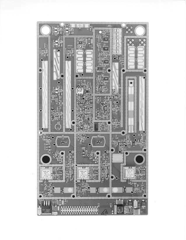
Click to zoom
Application Details
- Equipment Class
- DXX - Part 15 Low Power Communication Device Transmitter
- Date of Grant
- Nov 08, 1999
- Application Purpose
- Original Equipment
- Date of Application
- Mar 29, 1999
- Equipment Note
- UNII System
- Frequency Range
- 5782.00000000 - 5782.00000000
- Company
- WaveSpan Corporation
- Country
- United States
Documents & Files
Document Text
Text extracted from the exhibit documents filed with the FCC. Open a document above to read the original.
Users Manual
Stratum 100 Wireless Ethernet Bridge Installation and Maintenance Guide Copyright © 1999 Wavespan Corporation. All rights reserved. No part of this publication (whether in hardcopy or electronic form) may be reproduced or transmitted, in any form or by any means, electronic, mechanical, photocopying, recording, or otherwise, without the prior written consent of the publisher. Any information referred to herein is furnished under license with Wavespan Corporation and may only be used, copied, transmitted, stored, or printed in accordance with the terms of such license. This publication and the information herein is furnished AS IS, is subject to change without notice, and should not be construed as a commitment by Wavespan Corporation. Wavespan Corporation assumes no responsibility or liability for any errors or inaccuracies, makes no warranty of any kind (express, implied, or statutory) with respect to this publication, and expressly disclaims any and all warranties of merchantability, fitness for particular purposes, and noninfringement of third party rights. Wavespan is a trademark of Wavespan Corporation. Other brand or product names are the trademarks or registered trademarks of their respective holders. FCC Regulatory Compliance This device complies with Part 15 of the FCC Rules. Operation is subject to the following two conditions: (1) This device may not cause harmful interference, and (2) this device must accept any interference received, including interference that may cause undesired operation. This equipment has been tested and found to comply with the limits for a Class A digital device pursuant to Part 15 of the FCC Rules. These limits are designed to provide reasonable protection against harmful interference when the equipment is operated in a commercial environment. This equipment generates, uses, and can radiate radio frequency energy and, if not installed and used in accordance with the instruction manuals, may cause harmful interference to radio communications. Operation of this equipment in a residential area is likely to cause harmful interference in which case the user will be required to correct the interference at his own expense. The following information is for FCC compliance of unlicensed, intentional radiators. This equipment complies with FCC Regulation 15.407 as relating to point-to-point wireless communication. Modifications to this product not expressly approved by Wavespan Corporation could void the FCC approval and the user’s right to operate the product. Wavespan Corporation 500 N. Bernardo Avenue Mountain View, CA 94043 +1 650 919-0190 http://www.wavespan.com Printed in the United States of America 10 9 8 7 6 5 4 3 2 1031699 Safety Warning Before aiming the antenna or working near the antenna, read all of this manual and follow the instructions carefully. DO NOT STAND IN FRONT OF THE ANTENNA WHILE POWER IS ON. Be sure to provide adequate grounding and lightning protection. Do not install the Outdoor Unit near overhead electrical wires. This unit is intended for point-to-point operation over an unobstructed line-of-sight path. It is the responsibility of the installer to ensure the unit is properly installed in compliance with the FCC’s guidelines for maximum permissible radio frequency exposure outlined in CFR 47 Section 1.1307(b)(1), preventing excess exposure to all persons. The installed radiating device should be inaccessible to unauthorized personnel. The installed unit should be positioned to guarantee no direct continuous exposure to people within 5 feet of the antenna. During installation use caution to avoid excess exposures to directed antenna radiation within 3 feet of the front of the antenna. The transmit power output from the Stratum 100 is less than 15 milliwatts. However, after the gain of the standard 18-inch square antenna, the Effective Radiated Power is approximately 5.2 watts. Microwave radiation can cause tissue heating, potentially affecting the eyes, causing permanent damage to vision. Precautions when Rack Mounting the Stratum 100 When rack mounting your Stratum 100, you should the following precautions for safety and to ensure proper operation of the equipment: The maximum ambient temperature for the Stratum 100 IDU is 50degrees C. Care should be taken that when installed in a rack, whether closed or open, the ambient temperature within the rack should not exceed 50 degrees C. Stratum 100 IDUs have fans and ventilation holes to ensure proper air flow and maintain correct internal temperature. Do not block the fans or ventilation holes. When mounting any equipment in racks, you must take into account mechanical loading of the rack. Heavier equipment should be placed near the bottom of the rack and equipment should not be mounted in such a way as to cause instability. Special precautions should be taken with mountings that slide out for easier access to equipment. Such mountings can cause instability of the rack resulting in unsafe conditions and possible tipping of the rack. Ensure that the power source, wiring and over-current protection to rack mounted equipment is rated such that it can support the cumulative load of all equipment. Do not exceed the capacity of the wiring or over-current protection. Reliable grounding of the Stratum 100 is required. The rack should also be grounded. If power distribution strips are used, ensure that they are properly grounded. Stratum 100 Installation and Maintenance GuideContents •• i Contents About this Manual.............................................................................................................1 Whom This Manual is Intended For1 Additional Reading1 How This Manual Is Organized1 Conventions1 Introduction.......................................................................................................................3 Some Definitions3 Standard Configuration3 Installation...............................................................................................…
Text truncated - open the document above for the full version.
Test Report
Elliott Laboratories, Inc. -- EMC DepartmentTest Report Report Date: March 25, 1999 File: R31010Page 2 of 17 pages TABLE OF CONTENTS COVER PAGE....................................................................................... 1 TABLE OF CONTENTS............................................................................ 2 TABLE OF CONTENTS Continued.............................................................. 3 SCOPE................................................................................................ 4 OBJECTIVE.......................................................................................... 4 STATEMENT OF COMPLIANCE................................................................ 4 EMISSION TEST RESULTS...................................................................... 5 LIMITS OF CONDUCTED INTERFERENCE VOLTAGE........................... 5 LIMITS OF ANTENNA CONDUCTED SPURIOUS EMISSIONS................. 5 LIMITS OF RADIATED INTERFERENCE FIELD STRENGTH................... 6 MEASUREMENT UNCERTAINTIES.................................................. 7 COMPLIANCE EXPLANATION........................................................ 7 EQUIPMENT UNDER TEST (EUT) DETAILS................................................. 8 GENERAL................................................................................... 8 INPUT POWER............................................................................. 8 PRINTED WIRING BOARDS............................................................ 8 SUBASSEMBLIES......................................................................... 9 ENCLOSURE............................................................................... 9 EMI SUPPRESSION DEVICES.......................................................... 9 MODIFICATIONS.......................................................................... 9 SUPPORT EQUIPMENT.................................................................. 9 EXTERNAL I/O CABLING.............................................................. 10 TEST SOFTWARE........................................................................ 10 TEST SITE........................................................................................... 11 GENERAL INFORMATION............................................................. 11 CONDUCTED EMISSIONS CONSIDERATIONS................................... 11 RADIATED EMISSIONS CONSIDERATIONS...................................... 11 MEASUREMENT INSTRUMENTATION..................................................... 12 INSTRUMENT CONTROL COMPUTER............................................. 12 LINE IMPEDANCE STABILIZATION NETWORK (LISN)....................... 12 POWER METER........................................................................... 13 FILTERS/ATTENUATORS.............................................................. 13 ANTENNAS................................................................................ 13 ANTENNA MAST AND EQUIPMENT TURNTABLE.............................. 13 INSTRUMENT CALIBRATION........................................................ 13 TEST PROCEDURES.............................................................................. 14 EUT AND CABLE PLACEMENT...................................................... 14 CONDUCTED EMISSIONS............................................................. 14 RADIATED EMISSIONS................................................................. 14 CONDUCTED EMISSIONS FROM ANTENNA PORT............................. 14 SPECIFICATION LIMITS AND SAMPLE CALCULATIONS.............................. 15 CONDUCTED EMISSIONS SPECIFICATION LIMITS, SECTION 15.207.... 15 RADIATED EMISSIONS SPECIFICATION LIMITS, SECTION 15.209........ 15 SAMPLE CALCULATIONS - CONDUCTED EMISSIONS........................ 16 SAMPLE CALCULATIONS - RADIATED EMISSIONS........................... 17 Elliott Laboratories, Inc. -- EMC DepartmentTest Report Report Date: March 25, 1999 File: R31010Page 3 of 17 pages TABLE OF CONTENTS Continued... EXHIBIT 1:Test Equipment Calibration Data................................................. 1 EXHIBIT 2:Test Data Log Sheets............................................................... 2 EXHIBIT 3:Radiated Emissions Test Configuration Photographs.......................... 3 EXHIBIT 4:Conducted Emissions Test Configuration Photographs....................... 5 EXHIBIT 5:Proposed FCC ID Label & Label Location...................................... 7 EXHIBIT 6:Detailed Photographs of WaveSpan Model Stratum 100 Construction...... 8 EXHIBIT 7:Operator's Manual for WaveSpan Model Stratum 100........................ 9 EXHIBIT 8:Block Diagram of WaveSpan Model Stratum 100............................. 10 EXHIBIT 9:Schematic Diagrams for WaveSpan Model Stratum 100..................... 11 EXHIBIT 10: Theory of Operation for WaveSpan Model Stratum 100..................... 12 Elliott Laboratories, Inc. -- EMC DepartmentTest Report Report Date: March 25, 1999 File: R31010Page 4 of 17 pages SCOPE An electromagnetic emissions test has been performed on the WaveSpan Wireless Radio System model Stratum 100 pursuant to Subpart C of Part 15 of FCC Rules for intentional radiators. Conducted and radiated emissions data has been collected, reduced, and analyzed within this report in accordance with measurement guidelines set forth in ANSI C63.4-1992 as outlined in Elliott Laboratories test procedures. The intentional radiator above has been tested in a simulated typical installation to demonstrate compliance with the relevant FCC performance and procedural standards. Final system data was gathered in a mode that tended to maximize emissions by varying orientation of EUT, orientation of power and I/O cabling, antenna search height, and antenna polarization. Every practical effort was made to perform an impartial test using appropriate test equipment of known calibration. All pertinent factors have been applied to reach the determination of complian…
Text truncated - open the document above for the full version.
Test Report
Frequency Stability5/26/99 ODU B Serial Number:10020 Spectrum Analyzer:HP8561E Serial Number:3728A01990 Calibration Due:7/31/99 Calibration By:Continental Resources Calibration ID:9720C77030 Calibration Frequency (GHZ):5.800060 Frequency Stability vs. Temperature Oven Temp (C) ODU Temp (C) Voltage (VAC)Frequency (GHz)Freq. Accuracy (ppm) -30-191205.80009616.22 -20-81205.80009375.81 -1021205.80008754.74 0111205.80007412.43 10211205.80006650.17 20321205.8000512-1.52 30411205.8000413-3.22 40511205.8000382-3.76 50611205.800041-3.28 Frequency Stability vs. Input Voltage Oven Temp (C) ODU Temp (C) Voltage (VAC)Frequency (GHz)Freq. Accuracy (ppm) 25361205.8000517-1.43 25361005.8000546-0.93 25361405.8000523-1.33 25362405.8000508-1.59 25362045.8000502-1.69 25362765.8000504-1.66 Note: ODU Temp is the temperature measured inside the EUT enclosure.
Contact Information
Applicant
Roger Eline(Senior Technical Member)
415 988-6729Fax: 415 919-0191
Technical Contact
Elliott Laboratories, Inc.Mark R Briggs
[email protected]408-245-245-7800
684 West Maude Avenue · Sunnyvale, California · United States
Non-Technical Contact
Elliott Laboratories, Inc.Mark R Briggs
[email protected]408-245-245-7800
Technical Specifications
| # | Rule Parts | Frequency Range | Power Output | Tolerance |
|---|---|---|---|---|
| 2 | 15E | 5.78 GHz - 5.78 GHz | 400.00 µW | 100 ppm |
Other Applications from WaveSpan Corporation
NGP7058000
Sep 21, 1997Data Transmitter Maximum Output Power: 13.5 mW
Equipment Class
DSS - Part 15 Spread Spectrum Transmitter