NHAAD200PBelt clip wireless microphone
Add Electronics Co Ltd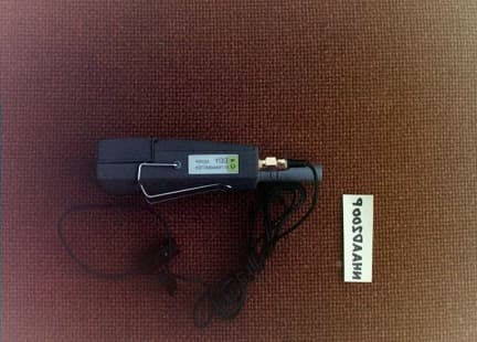
Click to zoom
Application Details
- Equipment Class
- TBT - Licensed Broadcast Transmitter Worn on Body
- Date of Grant
- Apr 06, 2000
- Application Purpose
- Original Equipment
- Date of Application
- Mar 12, 2000
- Equipment Note
- Belt clip wireless microphone
- Frequency Range
- 174.00000000 - 216.00000000
- Company
- Add Electronics Co Ltd
- Country
- South Korea
Documents & Files
Document Text
Text extracted from the exhibit documents filed with the FCC. Open a document above to read the original.
Users Manual
Appendix AFCC ID: NHAAD200H 1 OPERATIONS MANUAL
Cover Letter(s)
Hi, We are submitting a new exhibit that was requested by Correspondence Reference Number 13261, the complete emission designator information. If you have any questions, please feel free to contact myself or Bryan Broaddus ([email protected]) at any time. Thank You, Fred Gurule [email protected] DNB Engineering, Inc
External Photos
FCC ID: NHAAD200P External Photos FCC ID: NHAAD200P
ID Label/Location Info
FCC ID: NHAAD200PFCC ID: NHAAD200P ID LabelID Label NOTES: Label will be constructed of 0.02 inch aluminum as shown on the equipment with permanent adhesive. All information on the label will be etched or stamped. Both methods will exceed the expected lifetime of the equipment. The label will be large enough to allow all information to be legible. FCC ID: NHAAD200P
Internal Photos
FCC ID: NHAAD200P Internal Photos FCC ID: NHAAD200P
Operational Description
NHAAD200PNHAAD200P Operational Description NHAAD200PNHAAD200P
Parts List/Tune Up Info
FCC ID: NHAAD200PFCC ID: NHAAD200P Parts ListParts List FCC ID: NHAAD200PFCC ID: NHAAD200P 2.983 (d) (9)2.983 (d) (9)Tune-Up ProcedureTune-Up Procedure A. SW1 to OFF, VR1 to midrange and VR2 to midrange. B. Solder a 50 ohm coaxial cable (RG174) to the antenna terminal. C. Split this cable three ways to feed a spectrum analyzer, modulation analyzer and frequency counter D. On the modulation analyzer select 50 uS deemphasis, 15 kHz LPF, FM mode and connect its audio output to an audio analyzer for distortion measurement. E. Solder a shielded cable to the preamplifier output. F. Connect the other end of the shielded cable to an AC voltmeter. G. Apply 9 volts to the battery terminals and switch SW1 on. Adjust C29, C33, C42 and L2 for maximum power. H. Adjust L1 for the proper frequency (nine times the crystal frequency) and repeat step G. I. Apply 30 mV of audio at 1 kHz to the microphone terminals. Adjust VR2 for 775 mV preamplifier output. J. Adjust VR1 for 12 kHz deviation. Adjust L2 and C29 for minimum distortion and maximum power.
Schematics
FCC ID: NHAAD200PFCC ID: NHAAD200P SchematicSchematic
Test Report
FCC ID: NHAAD200PFCC ID: NHAAD200P 1 Application for CertificationApplication for Certification For an RF TransmitterFor an RF Transmitter ADD ADD ElecoEleco, Inc., Inc. 7207 Rio Flora Pl.7207 Rio Flora Pl. Downey, CA 90241Downey, CA 90241 Product: Wireless MicrophoneProduct: Wireless Microphone Model: AD200PModel: AD200P FCC ID: NHAAD200PFCC ID: NHAAD200P REPORT # RC054780/00096REPORT # RC054780/00096 This report was prepared in accordance with the requirements of the FCC Rules and Regulations Part 2, Subpart J, 2.981 through 2.1005, Part 74.801, 74.861 and other applicable sections of the rules as indicated herein. Prepared By: Jake Tynes DNB Engineering, Inc.DNB Engineering, Inc. 3535 W. Commonwealth Ave.3535 W. Commonwealth Ave. Fullerton, CA 92833Fullerton, CA 92833 7 MARCH 2000 FCC ID: NHAAD200PFCC ID: NHAAD200P 2 TABLE OF CONTENTSTABLE OF CONTENTS Section Title Sheet #Section Title Sheet # 1.0ADMINISTRATIVE DATA4 1.1Certifications and Qualifications4 1.2Measurement Repeatability Information4 Note: The paragraph numbers in this report follow the application section numbers found in the FEDERAL COMMUNICATIONS COMMISSION Rules and Regulations, Part 2, Subpart J for Type Certification of electronic equipment. 2.983 (a)Request for Certification5 2.983 (b)Equipment Description5 2.983 (c)Anticipated Production Quantity5 2.983 (d)Technical Description6 2.983 (d) (1)Type of Emissions6 2.983 (d) (2)Frequency Range6 2.983 (d) (3)Operating Power Level6 2.983 (d) (4)Maximum Power Allowed in Applicable Part(s) of the Rules6 2.983 (d) (5)Final RF Amplifier Input Power6 2.983 (d) (6)Function of all Active Circuit Devices7 2.983 (d) (7)Circuit Diagram8 2.983 (d) (8)Instruction Book8 2.983 (d) (9)Tune Up Procedure8 2.983 (d) (10)Description of Frequency Determining Circuitry9 2.983 (d) (11)Description of Suppression Circuitry9 2.983 (d) (12)Description of Digital Modulation System9 Figure 1: EUT Circuit Diagram10 Figure 2: EUT Block Diagram11 2.983 (e)Test Data12 2.983 (e) (1)Measurement of RF Power Output per 2.985 and 74.86112 Figure 3: Block Diagram for All Conducted Tests13 Figure 4: Equipment List14 Figure 5: Test Setup Photo for All Conducted Tests15 Figure 6: Plot of RF Power Output16 2.983 (e) (2)Measurement of Modulation Characteristics per 2.987 and 74.86117 - 19 Figure 7: Block Diagram of Modulation Characteristics Test20 Figure 8: Test Equipment Log21 Figure 9: Photo of Modulation Characteristics Calibration22 Figure 10: Photo of Modulation Characteristics Test 23 Figure 11: Test Data Sheet24 Figure 12: Frequency Response Curve25 2.983 (e) (3)Measurement of Occupied Bandwidth per 2.989 and 74.86126 Figure 13: Injected Audio Level27 Figure 14: Plot of Occupied Bandwith28 FCC ID: NHAAD200PFCC ID: NHAAD200P 3 TABLE OF CONTENTSTABLE OF CONTENTS Section Title Sheet #Section Title Sheet # 2.983 (e) (4)Measurement of Antenna Conducted Spurious Emissions per 2.991 and 74.86129 Figure 15: Highest Conducted Spurious Emissions30 Figures 16 - 18: Plots of Conducted Spurious Emissions31 - 33 2.983 (e) (5)Measurement of Radiated Spurious per 2.993 and 74.86134 - 35 Figure 19: RF Radiated Spurious Setup36 Figure 20: List of Radiated Spurious Test Equipment37 Figure 21: Photograph of Radiated Spurious Emissions Setup38 Figure 22: Photograph of Radiated Spurious Emissions Setup39 Figure 23: Photograph of Radiated Spurious Emissions Setup40 Figure 24: Photograph of Radiated Spurious Emissions Setup41 Figure 25: Radiated Spurious Emissions Test Data42 Figures 26 - 31: Plots of Radiated Spurious Emissions43 - 48 2.983 (e) (6)Measurement of Frequency Stability per 2.995 and 74.86149 Figure 32: Block Diagram of Frequency Stability Test50 Figure 33: Photograph of Frequency Stability Test Setup51 Figure 34: Photograph of Frequency Stability Test Setup52 Figure 35: Frequency Stability Test Data Sheet53 Figure 36: Frequency Stability Test Graph54 2.983 (e) (7)Frequency Spectrum to be Investigated per 2.99755 2.983 (f)FCC ID: Label55 2.983 (g)Photographs and/or Drawings Showing Equipment Construction Technique56 2.983 (h), (i)These sections are not applicable Figure 37: Wireless Microphone (Fully Assembled)57 Figure 38: Front Panel58 Figure 39: Wireless Microphone w/ Battery Removed 59 Figure 41: Board Detail 160 Figure 42: Board Detail 261 APPENDIX AOperating Manual1 - 5 FCC ID: NHAAD200PFCC ID: NHAAD200P 4 1.01.0ADMINADMINISTRATIVE DATAISTRATIVE DATA 1.11.1Certifications and QualificationsCertifications and Qualifications I certify that DNB Engineering, Inc conducted the tests performed in order to obtain the technical data presented in this application. Also, based on the results of the enclosed data, I have concluded that the equipment tested meets or exceeds the requirements of the Rules and Regulations governing this application. 1.21.2Measurement Repeatability InformationMeasurement Repeatability Information The test data presented in this report has been acquired using the guidelines set forth in FCC Part 2.981 through 2.1005, and Part 90. The test results presented in this document are valid only for the equipment identified herein under the test conditions described. Repeatability of these test results will only be achieved with identical measurement conditions. These conditions include: The same test distance, EUT Height, Measurement Site Characteristics, and the same EUT System Components. The system must have the same Interconnecting Cables arranged in identical placement to that in the test set- up, with the system and/or EUT functioning in the identical mode of operation (i.e. software and so on) as on the date of the test. Any deviation from the test conditions and the environment on the date of the test may result in measurement repeatability difficulties. All changes made to the EUT during the course of testing as identified in this test report must be incorporated into the EUT or identical models to ensure compliance with the FCC regulations. Bryan Broaddus (Para. 1.1) Manager, Test Dept. DNB E…
Text truncated - open the document above for the full version.
Contact Information
Technical Contact
DNB Engineering, Inc.Bryan C Broaddus
[email protected]714-870-7781
3535 W. Commonwealth Ave. · Fullerton, California · United States
Non-Technical Contact
ADD Eleco USA, Inc.Hyo-Chul Num
[email protected]562-927-5600
Test Firm
DNB Engineering, Inc.Bryan Broaddus
Technical Specifications
| # | Rule Parts | Frequency Range | Power Output | Emission | Tolerance |
|---|---|---|---|---|---|
| 1 | 74 | 174 MHz - 216 MHz | 4.90 mW | 48K0F3E | 0.0050000000 % |
Other Applications from Add Electronics Co Ltd
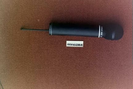
NHAAD200H
Mar 27, 2000Wireless microphone
Equipment Class
TBF - Licensed Broadcast Transmitter Held to Face