NI4TMLF8-5Smart LF Oscillator
Toyota Motor Corporation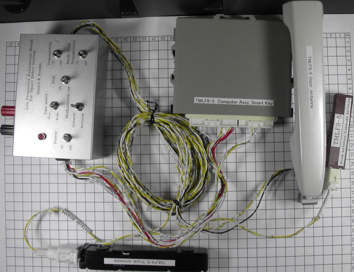
Click to zoom
Application Details
- Equipment Class
- DCD - Part 15 Low Power Transmitter Below 1705 kHz
- Date of Grant
- Dec 06, 2011
- Application Purpose
- Original Equipment
- Date of Application
- Dec 06, 2011
- Equipment Note
- Smart LF Oscillator
- Frequency Range
- 0.13420000 - 0.13420000
- Company
- Toyota Motor Corporation
- Country
- Japan
Documents & Files
Document Text
Text extracted from the exhibit documents filed with the FCC. Open a document above to read the original.
External Photos
Attachment A to File No.: T32612-03 1 P h o t o d o c u m e n t a t i o n o f t h e E U T Test Setup: 1.1 External views: Door Antenna: Room Antenna: Back Door Antenna: Smart ECU:
ID Label/Location Info
Smart LF Oscillator Model TMLF8-5 FCC ID:NI4TMLF8-5 Approval Label (Note) The layout and design of the approval label may be changed. The location of FCC ID code may be changed.
Internal Photos
1.2 Internal views: Smart ECU: Back Door Antenna: Door Antenna: Room Antenna:
Test Report
FCC ID: NI4TMLF8-5 mikes-testingpartners gmbh File No. T32612-03-00HU, page 1 of 22 Ohmstrasse 2-4 94342 STRASSKIRCHEN GERMANY Tel.:+49(0)9424-94810 Fax:+49(0)9424-9481240 Rev. No. 1.2, 9.9.2010 EMI − T E S T R E P O R T - FCC Part 15.209 - Test Report No. : T32612-03-00HU 06. December 2011 ______________________________________________________________________________________________ Date of issue Type / Model Name : TMLF8-5 Product Description : Smart LF Oscillator Applicant : Toyota Motor Corporation Address : 1, Toyota-Cho Toyota, Aichi, 471-8572 Japan Manufacturer : Toyota Motor Corporation Address : 1, Toyota-Cho Toyota, Aichi, 471-8572 Japan Licence holder : Toyota Motor Corporation Address : 1, Toyota-Cho Toyota, Aichi, 471-8572 Japan Test Result according to the standards listed in clause 1 test standards: POSITIVE The test report merely corresponds to the test sample. It is not permitted to copy extracts of these test results without the written permission of the test laboratory. FCC ID: NI4TMLF8-5 mikes-testingpartners gmbh File No. T32612-03-00HU, page 2 of 22 Ohmstrasse 2-4 94342 STRASSKIRCHEN GERMANY Tel.:+49(0)9424-94810 Fax:+49(0)9424-9481240 Rev. No. 1.2, 9.9.2010 Contents 1 T E S T S T A N D A R D S 3 2 S U M M A R Y 4 3 E Q U I P M E N T U N D E R T E S T 5 3.1 Photo documentation of the EUT – Detailed photos see Attachment A 5 3.2 Power supply system utilised 6 3.3 Short description of the Equipment under Test (EUT) 6 4 T E S T E N V I R O N M E N T 7 4.1 Address of the test laboratory 7 4.2 Environmental conditions 7 4.3 Statement of the measurement uncertainty 7 4.4 Measurement Protocol for FCC, VCCI and AUSTEL 8 5 T E S T C O N D I T I O N S A N D R E S U L T S 9 5.1 Conducted emissions 9 5.2 Field strength of the fundamental wave 10 5.3 Spurious emissions (magnetic field) 9 kHz – 30 MHz 13 5.4 Emission Bandwidth 17 6 U S E D T E S T E Q U I P M E N T A N D A C C E S S O R I E S 22 FCC ID: NI4TMLF8-5 mikes-testingpartners gmbh File No. T32612-03-00HU, page 3 of 22 Ohmstrasse 2-4 94342 STRASSKIRCHEN GERMANY Tel.:+49(0)9424-94810 Fax:+49(0)9424-9481240 Rev. No. 1.2, 9.9.2010 1 T E S T S T A N D A R D S The tests were performed according to following standards: FCC Rules and Regulations Part 15, Subpart A - General (November, 2011) Part 15, Subpart A, Section 15.31 Measurement standards Part 15, Subpart A, Section 15.33 Frequency range of radiated measurements Part 15, Subpart A, Section 15.35 Measurement detector functions and bandwidths FCC Rules and Regulations Part 15, Subpart C - Intentional Radiators (November, 2011) Part 15, Subpart C, Section 15.203 Antenna requirement Part 15, Subpart C, Section 15.205 Restricted bands of operation Part 15, Subpart C, Section 15.209 Radiated emission limits, general requirements ANSI C63.4: 2003 Methods of Measurement of Radio-Noise Emissions from Low- Voltage Electrical and Electronic Equipment in the Range of 9 kHz to 40 GHz. ANSI C95.1:1992 IEEE Standard for Safety Levels with respect to Human Exposure to Radio Frequency Electromagnetic Fields, 3 kHz to 300 GHz CISPR 16-4-2: 2003 Uncertainty in EMC measurement FCC ID: NI4TMLF8-5 mikes-testingpartners gmbh File No. T32612-03-00HU, page 4 of 22 Ohmstrasse 2-4 94342 STRASSKIRCHEN GERMANY Tel.:+49(0)9424-94810 Fax:+49(0)9424-9481240 Rev. No. 1.2, 9.9.2010 2 S U M M A R Y GENERAL REMARKS: The carrier frequency is 134.2 kHz FINAL ASSESSMENT: The equipment under test fulfills the EMI requirements cited in clause 1 test standards. Date of receipt of test sample : acc. to storage records Testing commenced on : 02. November 2011 Testing concluded on : 03. November 2011 Checked by: Tested by: Klaus Gegenfurtner Dipl.-Ing.(FH) Manager: Radio Group Huber Markus FCC ID: NI4TMLF8-5 mikes-testingpartners gmbh File No. T32612-03-00HU, page 5 of 22 Ohmstrasse 2-4 94342 STRASSKIRCHEN GERMANY Tel.:+49(0)9424-94810 Fax:+49(0)9424-9481240 Rev. No. 1.2, 9.9.2010 3 E Q U I P M E N T U N D E R T E S T 3.1 Photo documentation of the EUT – Detailed photos see Attachment A FCC ID: NI4TMLF8-5 mikes-testingpartners gmbh File No. T32612-03-00HU, page 6 of 22 Ohmstrasse 2-4 94342 STRASSKIRCHEN GERMANY Tel.:+49(0)9424-94810 Fax:+49(0)9424-9481240 Rev. No. 1.2, 9.9.2010 3.2 Power supply system utilised Power supply voltage: : 12.0 V / DC 3.3 Short description of the Equipment under Test (EUT) The Smart LF Oscillator TMLF8-5 is a transmitter installed in a motor vehicle and is used as part of the Smart System. In the System, the Smart LF Oscillator has mainly following functions: - Smart Door Unlocking Door antennas transmit a low frequency at 134.2 kHz intermittently. An electronic key, carried out by the driver, will transmit a high radio wave when recognized the signal. - Smart Trunk Unlocking The trunk antenna provides the signal for the electronic key to open the trunk. - Detection of Electronic Key inside Trunk If the driver tries to close the trunk, the inside Trunk antenna transmit a radio wave of 134.2 kHz. The electronic key left inside the trunk will recognize the signal and transmits a high radio frequency back to alarm the driver. - Smart Engine Start When the driver is inside the car the inside Room antenna transmits a radio wave of 134.2 kHz. If the electronic key recognize the signal it transmits a high radio frequency back to trigger the engine start mechanism. The tests were performed on three antenna types in conjunction with Computer assy (ECU): 1. Door antenna 2. Room antenna / Luggage antenna 3. Trunk antenna Number of tested samples: 1 EuT operation mode: The equipment under test was operated during the measurement under the following conditions: - Transmit mode CW (unmodulated) at 134.2 kHz - Transmit mode modulated at 134.2 kHz EuT configuration: (The CDF filled by the applicant can be viewed at the test laboratory.) The following peripheral devices and interface cables were connected during the measurements: - Test box Model : Supplied by the manu…
Text truncated - open the document above for the full version.
Contact Information
Applicant
Arinobu Kimura
Test Firm
CSA Group Bayern GmbHThomas Weise
Technical Specifications
| # | Rule Parts | Frequency Range | Power Output |
|---|---|---|---|
| 1 | 15C | 0.1342 MHz - 0.1342 MHz | - |
Other Applications from Toyota Motor Corporation

NI4TMLF19D-5
Jan 17, 2023Smart LF oscillator
Equipment Class
DCD - Part 15 Low Power Transmitter Below 1705 kHz
NI4TMLF15-4
Dec 14, 2021Smart LF Oscillator
Equipment Class
DCD - Part 15 Low Power Transmitter Below 1705 kHz
NI4TS-GTY
May 25, 2021Smart LF Oscillator
Equipment Class
DCD - Part 15 Low Power Transmitter Below 1705 kHz
NI4TMLF19D-3
Apr 18, 2021Smart LF oscillator
Equipment Class
DCD - Part 15 Low Power Transmitter Below 1705 kHz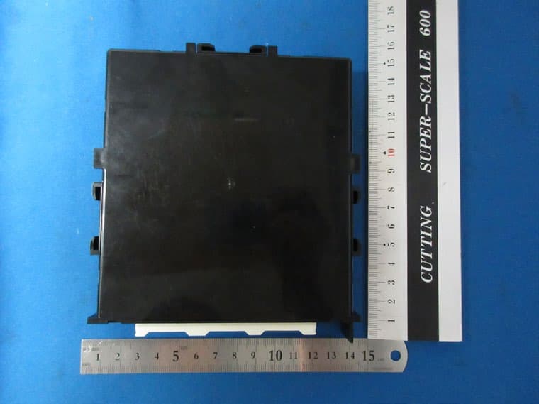
NI4TMLF19T-2
Mar 16, 2021Smart LF Oscillator
Equipment Class
DCD - Part 15 Low Power Transmitter Below 1705 kHz