NJC-DTF-510LCD Monitor
Foxlink Image Technology Co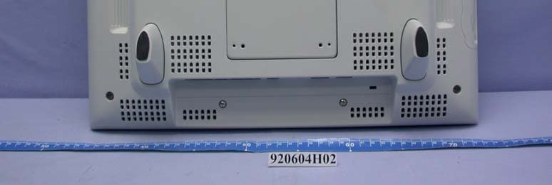
Click to zoom
Application Details
- Equipment Class
- JBP - Part 15 Class B Computing Device Peripheral
- Date of Grant
- Jul 21, 2003
- Application Purpose
- Original Equipment
- Date of Application
- Jul 21, 2003
- Equipment Note
- LCD Monitor
- Company
- Foxlink Image Technology Co
- Country
- Taiwan
Documents & Files
Document Text
Text extracted from the exhibit documents filed with the FCC. Open a document above to read the original.
Users Manual
DTF-510U CAUTION Be sure to use a grounded power source when applying power to DTF-510U. If the LCD screen has been damaged, DO NOT touch any liquid that may be leaking from it; this liquid is an irritant. In case of contact with skin, eyes, or mouth, rinse immediately with running water for at least 15 minutes or more. If contact is made with the eyes or mouth, also consult a physician. WARNING Do not use DTF-510U Interactive Pen Display in a facility control system that requires extremely high reliability; it may cause other electronic devices to malfunction, or other devices may cause the Interactive Pen Display to malfunction. Where use is prohibited, power off DTF-510U to prevent the possibility of it causing other electronic devices to malfunction. Wacom does not accept any liability for direct or consequential damages. For details, please refer to your Warranty, located at the end of this manual. Do not open DTF-510U. It has the risk of electric shock. HIGH VOLTAGE Only use the AC adaptor that came with DTF-510U. If a different type of AC adaptor is used, DTF- 510U will not work properly or it may be damaged. Using a different type of AC adaptor also has the potential to result in fire. Use of a different AC adaptor will void your warranty. Prevent your children from swallowing the pen nib or side switch. � The pen nib or side switch may accidentally be pulled out if children are biting on them. SAFETY INSTRUCTIONS Introduction and Overview The Wacom® DTF-510U Interactive Pen Display combines an LCD monitor with a Wacom tablet. This gives you a direct point-and-draw-on-screen interface that can be used with a Personal Computer (PC) or Macintosh computer. DTF-510U basic components include a Wacom tablet internally mounted behind a 15.0" diagonal TFT color LCD monitor, and Wacom’s pen. Your DTF-510U Interactive Pen Display offers a number of significant advantages over a standard monitor: Reduced power consumption Reduced heat generation Requires less work space Flicker free and easier on the eyes Integrated input and display Pressure-sensitive drawing directly on the display screen. This manual describes how to install DTF-510U hardware and software. It also describes how to use DTF- 510U and the pen. Note that the computer treats the two parts of DTF-510U (the LCD monitor and the Wacom tablet) as separate pieces of hardware. Therefore, the installation process is completed in two stages. First, you will install the LCD monitor portion of DTF-510U. In the second stage you will install DTF-510U’s tablet functionality. You can find information on using the Wacom Tablet Control Panel for customizing your tablet and pen set- tings in the online Help, located under the Help menu in the Wacom Tablet Control Panel. The following are not included with this product: Information about your specific computer hardware Information about your operating system Information about application software. Please refer also to your computer hardware, operating system, or software application manuals. To use the pressure-sensitivity of the pen with your favorite drawing application, refer to instructions in that application’s manuals. Precautions on Use and Handling This product is for use with a VGA graphics card; � using an inappropriate graphics card may damage DTF-510U. Do not disassemble DTF-510U or pen. This may cause DTF-510U or pen to malfunction. In this case, Wacom shall have no responsibility to repair or replace the product. Do not use or store DTF-510U where: - Temperature changes are severe (e.g., outdoors or inside a vehicle). - DTF-510U and pen are exposed to direct sunlight or heat from an appliance. - DTF-510U and pen are exposed to water or any other kind of liquid. - Temperature or humidity exceeds the specifications. Do not block the ventilation holes in the rear panel; this may overheat and damage DTF-510U. Do not use DTF-510U in a dusty environment; It may damage the unit. Do not scratch the cover glass of DTF-510U. � Avoid placing sharp objects on the glass surface. Do not use detergent to clean the cover glass of DTF-510U; this may alter the surface friction and deteriorate the handwriting feel. Be sure to follow all instructions, cautions, and warnings found within this manual. Failure to do so could void your warranty, in which case Wacom shall have no responsibility to repair or replace the product. Do not put heavy articles on the Interactive Pen Display; � this may damage the display screen or stand. Do not place heavy article on DTF-510U cabling, repeatedly bend the cables, or apply heavy stress on the the cable connectors; this may damage the unit or your cabling. Do not connect or disconnect the power cable while DTF-510U or your computer is turned on; � it may damage the LCD display or computer video card. 4 Table of Contents Checking Packed Components 5 Installation 6 LCD Monitor Installation Tablet Software Installation for Windows and Macintosh Customizing DTF-510U – The Basics 8 Opening the Wacom Tablet Control Panel Calibrating the Tablet DTF-510U Component Functions 10 Front View Rear View Side Cover Installation Using an Alternate Mount or Stand Using the Pen 14 Pen Using a Pen Adjusting the LCD Monitor 16 Factory Presets, Auto Adjust, and User Settings Working with OSD (On Screen Display) Menu Adjusting Pitch and Phase Power Saving Caring For Your DTF-510U 20 Cleaning Replacing the Pen Tip Display Troubleshooting 21 Specifications 23 General Specifications LCD Display Tablet Power Adaptor Pen Pen Accessories Appendix 25 Warranty on Sales in Asia-Pacific area 5 Checking Packed Components In your package you will find the following items: USB Cable VGA Cable* DTF-510U main unit Pen User’s Manual Wacom Software CD Contains the Interactive Pen Display software and a Readme file (Windows/Macintosh) AC Adaptor and Cable * * For the DTF-510U only. Do not use with other devices. Please retain the package box for use when storing or shipping DTF-510U. 6 Installation LCD M…
Text truncated - open the document above for the full version.
External Photos
Page 1 CONSTRUCTION PHOTOS OF EUT
ID Label/Location Info
(Fig. 1) FCC ID: NJC-DTF-510 FCC LABEL LOCATION The label will be permanently affixed at a conspicuous location on the device. Label
Internal Photos
Page 2 Page 3 Page 4 Page 5 Page 6 Page 7 Page 8 Page 9 Page 10 Page 11 Page 12 Page 13 Page 14 Page 15 Page 16 Page 17 Page 18
Operational Description
FCC ID: NJC-DTF-510 Report No.: 920604H02 ADT No.: 920604H02 Operational Description DTF-510U is an input / output integrated device for a computer, using Wacom’s sensor, an erasing Pen and a 15.0 inch TFT color LCD monitor. The tablet continuously transmits data to and from the Pen. When transmitting, the tablet sends a signal to the Pen. The Pen stores energy from the signal. When receiving, the Pen sends a signal that carries coordinate, switch, and pressure data back to the tablet. The tablet sends this data to the computer. DTF-510U provides a Pen computing. Pen LCD monitor Sensor Shield FCC ID: NJC-DTF-510 Report No.: 920604H02 ADT No.: 920604H02 The intentionally radiated frequencies The intentionally radiated frequency is 600kHz. All the other frequencies are unintentionally radiated. A. Antenna The sensor board has two kinds, transmitter and receiver. The transmission sensor board has multiple loop coils in horizontal directions. Each coil is approximately 34.5mm wide. Each coil consists of 8 turns (loops) of copper conductor. Radio frequency energy is radiated from these coils. The receiver sensor board has two groups of multiple loop coils in X (horizontal) and Y (vertical) directions. Each coil is approximately 28.8mm wide and as long as the height, for the X-axis, and width, for the Y-axis, of the effective area of the tablet. Each coil consists of one turn (loops) of silver conductor. B. Original oscillation frequency and intentionally radiated frequency We make one (600kHz) intentionally radiated frequency from the original oscillation frequency of 600kHz by microcomputer. C. Operation The tablet looks for a pointing device, such as a stylus, by feeding electrical current of above-mentioned frequency through the coils in both X axis and Y axis. The current fed through each coil is not more than 40mA . The tablet is able to detect the position of a pointing device because of the induction caused between the coil of the pointing device and two coils, one from X-axis and the other from Y-axis, of the sensor board. D. Comment on pointing device The pointing device operates completely passively and has no battery or active oscillator.
Test Report
Report No.: D920604H021Issued: Jul. 11, 2003 ADT No.: 920604H02 FCC TEST REPORT REPORT NO. : RF920604H02 MODEL NO. : DTF-510X RECEIVED : Jun. 04, 2003 TESTED : Jun. 16 to 25, 2003 APPLICANT : Foxlink Image Technology CO., LTD ADDRESS : 11, Lane 596, Chien Hsing Road Sec.2, Hsinfeng, Hsinchu,Taiwan ISSUED BY : Advance Data Technology Corporation LAB LOCATION : No. 81-1, Lu Liao Keng, 9 Ling, Wu Lung Tsuen, Chiung Lin Hsiang, Hsin Chu Hsien, Taiwan, R.O.C. This test report consists of 23 pages in total. It may be duplicated completely for legal use with the approval of the applicant. It should not be reproduced except in full, without the written approval of our laboratory. The client should not use it to claim product endorsement by any U.S. government agencies. The test results in the report only apply to the tested sample. The test results in this report are traceable to the national or international standards. Lab Code: 200376-0 Report No.: D920604H022Issued: Jul. 11, 2003 ADT No.: 920604H02 Table of Contents 1CERTIFICATION.........................................................................................................3 2SUMMARY OF TEST RESULTS.............................................................................4 3GENERAL INFORMATION.......................................................................................5 3.1GENERAL DESCRIPTION OF EUT........................................................................5 3.2DESCRIPTION OF SUPPORT UNITS...................................................................7 4EMISSION TEST......................................................................................................10 4.1CONDUCTED EMISSION MEASUREMENT......................................................10 4.1.1LIMITS OF CONDUCTED EMISSION MEASUREMENT..................................10 4.1.2TEST INSTRUMENTS.............................................................................................10 4.1.3TEST PROCEDURE................................................................................................11 4.1.4DEVIATION FROM TEST STANDARD.................................................................11 4.1.5TEST SETUP............................................................................................................11 4.1.6EUT OPERATING CONDITIONS..........................................................................12 4.1.7TEST RESULTS.......................................................................................................13 4.2RADIATED EMISSION MEASUREMENT............................................................15 4.2.1LIMITS OF RADIATED EMISSION MEASUREMENT.......................................15 4.2.2TEST INSTRUMENTS.............................................................................................16 4.2.3TEST PROCEDURE................................................................................................17 4.2.4DEVIATION FROM TEST STANDARD.................................................................17 4.2.5TEST SETUP............................................................................................................18 4.2.6EUT OPERATING CONDITIONS..........................................................................18 4.2.7TEST RESULTS.......................................................................................................19 5PHOTOGRAPHS OF THE TEST CONFIGURATION.........................................21 6APPENDIX - INFORMATION ON THE TESTING LABORATORIES...............23 Report No.: D920604H023Issued: Jul. 11, 2003 ADT No.: 920604H02 1 CERTIFICATION PRODUCT : LCD Monitor MODEL NO. : DTF-510X BRAND : WACOM APPLICANT : Foxlink Image Technology CO., LTD STANDARDS : 47 CFR Part 15, Subpart C (Section 15.209), ANSI C63.4-1992 We, Advance Data Technology Corporation, hereby certify that one sample (Model: DTF-510X) of the designation has been tested in our facility from Jun. 16 to 25, 2003. The test record, data evaluation and Equipment Under Test (EUT) configurations represented herein are true and accurate accounts of the measurements of the sample's EMC characteristics under the conditions herein specified. PREPARED BY:, DATE:Jul. 11, 2003 ( Amanda Chu ) APPROVED BY:, DATE: Jul. 11, 2003 ( Eric Lin, Manager ) Report No.: D920604H024Issued: Jul. 11, 2003 ADT No.: 920604H02 2 SUMMARY OF TEST RESULTS The EUT has been tested according to the following specifications: APPLIED STANDARD: 47 CFR Part 15, Subpart C StandardTest TypeResultRemarks Conducted TestPASS Meets Class B Limit Minimum passing margin is -17.82 dB at 0.210 MHz 47 CFR Part 15, Subpart C Radiated TestPASS Meets Class B Limit Minimum passing margin is –6.5 dB at 38.38 MHz NOTE: For conducted emission test, the test limit used is according to FCC Part 15.107. In this part, conducted emission test for telecom port is not mentioned and therefore this item is not tested. Report No.: D920604H025Issued: Jul. 11, 2003 ADT No.: 920604H02 3 GENERAL INFORMATION 3.1 GENERAL DESCRIPTION OF EUT PRODUCT LCD Monitor MODEL NO. DTF-510X POWER SUPPLY 12VDC from AC adapter FREQUENCY RANGE 600KHz DATA CABLE NA ANTENNA TYPE Loop Antenna I/O PORTS VGA in, VGA out, USB HUB, DC in ASSOCIATED DEVICES VGA cable shielded (2.0m) with two ferrite cores USB cable shielded (2.0m) with one ferrite core Note: 1. The EUT must be supplied with a power adapter and following two different brands could be chosen: AdapterBRANDMODEL NAMESPECIFICATION 1LIEN CHANGLCA01FI/P: 100-250Vac, 47-63Hz O/P: 12Vdc, 3.3A 2HJCHASV05FB57I/P: 90-264Vac, 47-63Hz O/P: 12Vdc, 3.0A 2. For more detailed features description, please refer to the manufacturer's specifications or User's Manual. Report No.: D920604H026Issued: Jul. 11, 2003 ADT No.: 920604H02 3.2 DESCRIPTION OF TEST MODES One channel is provided to this EUT. ChannelFrequency 1 600KHz NOTE: X, Y and Z axis were pre-tested in chamber. The X axis, worst case one, was chosen for final test. The EUT wa…
Text truncated - open the document above for the full version.
Test Setup Photos
Report No.: D920604H0221Issued: Jul. 11, 2003 ADT No.: 920604H02 5 PHOTOGRAPHS OF THE TEST CONFIGURATION CONDUCTED EMISSION TEST Report No.: D920604H0222Issued: Jul. 11, 2003 ADT No.: 920604H02 RADIATED EMISSION TEST
Contact Information
Applicant
Hsing Chen(Manager)
Technical Contact
Advance Data Technology Corp.Eric Lin
[email protected]+866-3-593-5343
81-1 Luliaoken 9th Lin, Wulung Tsuen · Hsinchu · Taiwan
Test Firm
Bureau Veritas CPS (H.K.) Ltd. Taoyuan BranchRichard Chen
Technical Specifications
| # | Rule Parts | Frequency Range | Power Output |
|---|---|---|---|
| 1 | 15B | - | - |
Other Applications from Foxlink Image Technology Co
NJC-SHNGD1403A
Jul 31, 2026RF-Module
Equipment Class
DTS - Digital Transmission System
NJCDP36VC
Sep 21, 1999Scanner
Equipment Class
JBP - Part 15 Class B Computing Device Peripheral
NJCDC66J
Aug 11, 1999Scanner Model: DC66J
Equipment Class
JBP - Part 15 Class B Computing Device Peripheral
NJCDP66VI
Feb 17, 1999Color Flatbed Scanner
Equipment Class
JBP - Part 15 Class B Computing Device Peripheral
NJCDP66VS
Feb 17, 1999Color Scanner
Equipment Class
JBP - Part 15 Class B Computing Device Peripheral