NKR-RFRBCARDROCKETBOOST READY CARD-RF-RBCARD
Wistron NeWeb Corporation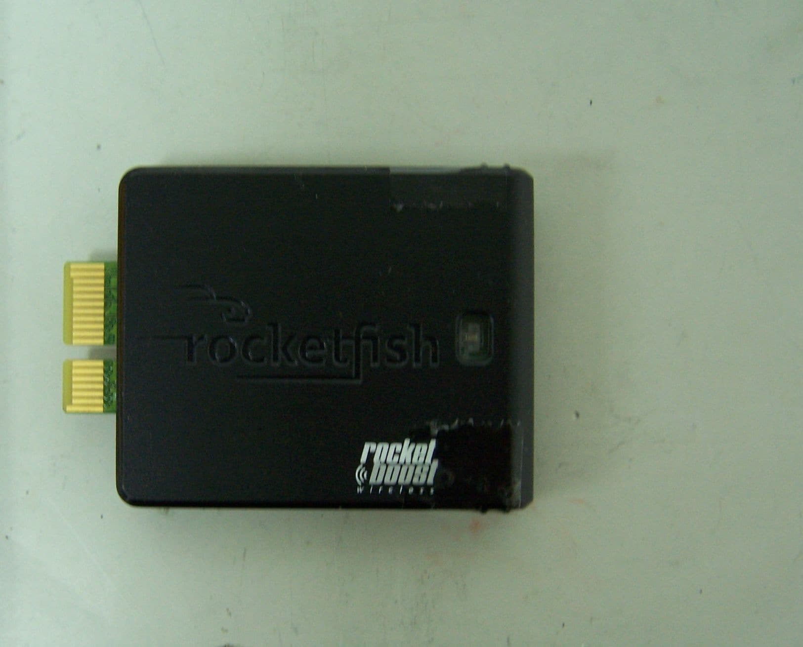
Click to zoom
Application Details
- Equipment Class
- DTS - Digital Transmission System
- Date of Grant
- Aug 17, 2010
- Application Purpose
- Original Equipment
- Date of Application
- Aug 16, 2010
- Equipment Note
- ROCKETBOOST READY CARD-RF-RBCARD
- Frequency Range
- 2412.00000000 - 2462.00000000
- Company
- Wistron NeWeb Corporation
- Country
- Taiwan
Documents & Files
Document Text
Text extracted from the exhibit documents filed with the FCC. Open a document above to read the original.
External Photos
Page 1 of 1 Type Designation: RF-RBCARD Report Number: 17016719 001 Fig. 1: External view Fig. 2: External view
Internal Photos
Page 1 of 2 Type Designation: RF-RBCARD Report Number: 17016719 001 Fig. 1: Internal view Fig. 2: Internal view Page 2 of 2 Type Designation: RF-RBCARD Report Number: 17016719 001 Fig. 3: Internal view
Operational Description
Operational Description The device is a 2.4GHz wireless Radio module, which operates in the 2.4GHz frequency spectrum. The transmitter of the EUT is powered by 5.0V dc from the host equipment. The antenna is printed monopole antenna without antenna connector. RF PRODUCT SPEC Frequency range : 2412 ~ 2462MHz Channel spacing : 26 & 24MHZ Channel List : 2412, 2438, 2462MHz(only 3 ch) Modulation type / technology : OFDM, 64 sub-carriers, pi/4 DQPSK L.O. frequency of receiver : 2412, 2438, 2462 MHz Data Rate : 27.55Mbps over-the-air rate (constant), 20.33Mbps demod RF power(conducted power or EIRP) : EIRP 18.0dBm Antenna type & gain : printed monopole with 2dBi gain Continue TX/RX method : Use AM2Gtest to do Cont. TX/RX(this Tool is only for RF test) Duty Cycle : ~ 100% Power supply : 5.0V
RF Exposure Info
Maximum Permissible Exposure (MPE) Evaluation 1. Limits 2. Estimation of compliance boundary For the final determination of the compliance boundary, the method for far-field calculation is used. 2 4R PG S π = Where: S = power density (in appropriate units, e.g. mW/cm2) P = power input to the antenna (in appropriate units, e.g., mW) G = power gain of the antenna in the direction of interest relative to an isotropic radiator R = distance to the center of radiation of the antenna (appropriate units, e.g., cm) The information of the EUT: Frequency range: 2412MHz to 2462MHz Maximum Power input to antenna: 2412MHz, 24.41dBm (276mW) Max Antenna gain: 2 dBi (1.58) The overall exposure at 20 cm from the EUT: 2 2 /087.0 204 58.1276 cmmWS= ×× × = π The S at the position which is 20cm far from the EUT is smaller than the uncontrolled exposure limit line. So the EUT also complies with the limits for occupational/controlled exposure.
Test Report
Produkte Products Prüfbericht - Nr.: Test Report No. 17016719 001 Seite 2 von 42 Page 2 of 42 TEST SUMMARY 5.1.1 ANTENNA REQUIREMENT RESULT: Passed 5.1.2 PEAK OUTPUT POWER RESULT: Passed 5.1.3 6DB BANDWIDTH RESULT: Passed 5.1.4 99% BANDWIDTH RESULT: Passed 5.1.5 CONDUCTED SPURIOUS EMISSION MEASURED IN 100KHZ BANDWIDTH RESULT: Passed 5.1.6 PEAK POWER DENSITY RESULT: Passed 5.1.7 SPURIOUS EMISSION RESULT: Passed 5.1.8 CONDUCTED EMISSIONS RESULT: Passed 5.1.9 RADIATED EMISSIONS RESULT: Passed 5.1.10 RESTRICTED BANDS RESULT: Passed Produkte Products Prüfbericht - Nr.: Test Report No. 17016719 001 Seite 3 von 42 Page 3 of 42 Contents 1. GENERAL REMARKS......................................................................................................... 4 1.1 COMPLEMENTARY MATERIALS.......................................................................................... 4 2. TEST SITES...................................................................................................................... 4 2.1 TEST FACILITIES............................................................................................................... 4 2.2 LIST OF TEST AND MEASUREMENT INSTRUMENTS............................................................... 5 2.3 TRACEABILITY.................................................................................................................. 6 2.4 CALIBRATION................................................................................................................... 6 2.5 MEASUREMENT UNCERTAINTY........................................................................................... 6 2.6 LOCATION OF ORIGINAL DATA........................................................................................... 6 2.7 STATUS OF FACILITY USED FOR TESTING........................................................................... 6 3. GENERAL PRODUCT INFORMATION.................................................................................... 7 3.1 PRODUCT FUNCTION AND INTENDED USE........................................................................... 7 3.2 RATINGS AND SYSTEM DETAILS........................................................................................ 7 3.3 INDEPENDENT OPERATION MODES.................................................................................... 8 3.4 NOISE GENERATING AND NOISE SUPPRESSING PARTS....................................................... 8 3.5 SUBMITTED DOCUMENTS.................................................................................................. 8 4. TEST SET-UP AND OPERATION MODES.............................................................................. 9 4.1 PRINCIPLE OF CONFIGURATION SELECTION........................................................................ 9 4.2 TEST OPERATION AND TEST SOFTWARE............................................................................ 9 4.3 SPECIAL ACCESSORIES AND AUXILIARY EQUIPMENT.......................................................... 9 4.4 COUNTERMEASURES TO ACHIEVE EMC COMPLIANCE......................................................... 9 4.5 TEST SETUP DIAGRAM.................................................................................................... 10 5. TEST RESULTS............................................................................................................... 12 5.1 TRANSMITTER REQUIREMENT & TEST SUITES.................................................................. 12 5.1.1 Antenna Requirement ................................................................................................................12 5.1.2 Peak Output Power ....................................................................................................................13 5.1.3 6dB Bandwidth ...........................................................................................................................17 5.1.4 99% Bandwidth ..........................................................................................................................21 5.1.5 Conducted Spurious Emission measured in 100kHz Bandwidth...............................................25 5.1.6 Peak Power Density ...................................................................................................................30 5.1.7 Spurious Emission .....................................................................................................................34 5.1.8 Conducted emissions .................................................................................................................35 5.1.9 Radiated emissions ....................................................................................................................36 5.1.10 Restricted bands ....................................................................................................................37 6. PHOTOGRAPHS OF THE TEST SET-UP.............................................................................. 38 7. LIST OF TABLES............................................................................................................. 42 8. LIST OF PHOTOGRAPHS.................................................................................................. 42 Produkte Products Prüfbericht - Nr.: Test Report No. 17016719 001 Seite 4 von 42 Page 4 of 42 1. General Remarks 1.1 Complementary Materials All attachments are integral parts of this test report. This applies especially to the following appendix: Appendix 1: Test Result 2. Test Sites 2.1 Test Facilities TÜV Rheinland (Guangdong) Ltd. EMC Laboratory Guangzhou Auto Market, Yuan Gang Section of Guangshan Road, Guangzhou, P.R. China FCC Registration No.: 833845 Test site Industry Canada No.: 2932C-1 Produkte Products Prüfbericht - Nr.: Test Report No. 17016719 001 Seite 5 von 42 Page 5 of 42 2.2 List of Test and Measurement Instruments Table 1: List of Test and Measurement Equipment Kind of Equipment Manufact…
Text truncated - open the document above for the full version.
Test Setup Photos
Produkte Products Prüfbericht - Nr.: Test Report No. 17016719 001 Seite 36 von 40 Page 36 of 40 6. Photographs of the Test Set-Up Photograph 1: Set-up for Radiated Emissions Photograph 2: Set-up for Transmitter test Produkte Products Prüfbericht - Nr.: Test Report No. 17016719 001 Seite 37 von 40 Page 37 of 40 Photograph 3: Set-up for Spurious Emissions (9kHz-30MHz) Photograph 4: Set-up for Spurious Emissions (30MHz-1GHz) Produkte Products Prüfbericht - Nr.: Test Report No. 17016719 001 Seite 38 von 40 Page 38 of 40 Photograph 5: Set-up for Spurious Emissions (1GHz-18GHz) Photograph 6: Set-up for Spurious Emissions (18GHz-26GHz) Produkte Products Prüfbericht - Nr.: Test Report No. 17016719 001 Seite 39 von 40 Page 39 of 40 Photograph 7: Set-up for Conducted Emissions
Contact Information
Applicant
William Su(Senior Director / System Engineering dept.)
Test Firm
TUV Rheinland (GuangDong) Ltd.Yuxin Huang
Technical Specifications
| # | Rule Parts | Frequency Range | Power Output |
|---|---|---|---|
| 1 | 15C | 2.41 GHz - 2.46 GHz | 276.00 mW |
Other Applications from Wistron NeWeb Corporation
NKR-ATTCGW453
Aug 25, 2026Enterprise product
Equipment Class
NII - Unlicensed National Information Infrastructure TXNKR-LS06B
Aug 24, 2026Touchscreen
Equipment Class
NII - Unlicensed National Information Infrastructure TXNKR-DWSZW
Aug 10, 2026Door/Window Sensor
Equipment Class
DXX - Part 15 Low Power Communication Device TransmitterNKR-TELE2
Jun 26, 2026TELE2
Equipment Class
NII - Unlicensed National Information Infrastructure TXNKR-VMC-SA525MAX
Jun 05, 2026NAD (Network Access Device)
Equipment Class
CXX - Communications Rcvr for use w/ licensed Tx and CBs