NKR-SWA16Wireless Audio Module
Wistron NeWeb Corporation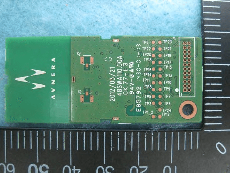
Click to zoom
Application Details
- Equipment Class
- DTS - Digital Transmission System
- Date of Grant
- Oct 07, 2014
- Application Purpose
- Original Equipment
- Date of Application
- Oct 06, 2014
- Equipment Note
- Wireless Audio Module
- Frequency Range
- 2405.35000000 - 2477.35000000
- Company
- Wistron NeWeb Corporation
- Country
- Taiwan
Documents & Files
Document Text
Text extracted from the exhibit documents filed with the FCC. Open a document above to read the original.
Users Manual
CONFIDENTIAL | PROVIDED UNDER NDA General Description The SWA16 module family of products represents a new level of system integration offering customers fast time to market with a point-to-point mono, or stereo, wireless connection. These modules are optimized for low-cost, high-quality and ease-of-use. The module incorporates Avnera’s proprietary wireless audio protocol, designed from the ground up specifically for audio. It features low fixed latency, uncompressed CD quality mono or stereo audio, superior interference immunity and industry leading coexistence with WiFi – even at close proximity to a WiFi device. The SWA16 module integrates all features necessary to complete a wireless stereo ro mono link, including AV6100 Wireless Audio Chip, printed diversity antenna, flash memory, interface connector and all passive components. Just supply 5 Volts and an I2S interface and you are ready to create a wireless audio link. The module measures just 26 x 60 x 3.5 mm and is provided with a 24 pin FPC connector or pin header for connection to the system board. The module is certified to FCC and CE standards. Applications Wireless Subwoofers Stereo Wireless Rear Speakers Soundbar / Audio Video Receiver / BluRay Mono/Stereo Audio Channel Transmission Ordering Options SWA16-TX: Transmit module with digital audio input SWA16- RX: Receive module with digital audio output Features Audio Interfaces I2S Digital Input / Output interface with >94dB end-to-end digital audio path Wireless Range > 15m Non Line Of Sight (NLOS) range > 50m Line Of Sight (LOS) range Frequency range: 2.4 GHz ISM band, continuous dynamic frequency selection Forward error correction coding, error detection, and audio-specific error concealment Dual printed PCB diversity antennas for multipath and fading mitigation Auto-search/synch and dynamic channel selection Low and fixed latency 24 pin FPC or pin header connector Sample rate converter: Support for 32 - 96kHz input sample rates Over-the-air firmware update capability Customizable firmware for simple, low-cost, sub-woofer amplifier implementations General purpose over-the-air (OTA) serial interface: 11 kbps, bi-directional, full duplex Support for amplifier control data, meta- data, and remote control commands SWA16-TX/RX Module Datasheet Mono/Stereo Wireless Audio System, based on the Avnera AV6100 IC We use diff. label colors to distinguish between TX and RX. SWA16 Module Datasheet Rev 1.0 CONTENTS SUBJECT TO CHANGE WITHOUT NOTICE 2 CONFIDENTIAL 1 SWA16 Functional The SWA16 module is available in 2 variations; digital input transmitter module or digital output receiver module. There is a separate I2S port for digital audio input and output functions and either of these can be configured to be a master or a slave – only the input or output port can be active at any time. In addition, MCLK can be generated from the module, or input to the module as required by the system application. The hardware for the audio input (transmit) and audio output (receive) versions of the module is identical and only the firmware loaded on the module determines its function. The highly integrated nature of the AV6100 transceiver IC results in few external components being required for the SWA16 module design. 2 Printed antennas are used to achieve increased range, and to offer diversity, and the simple RF path consists only of the antennas, associated tuning components, the RF switch and a balun connected to the AV6100 IC. A 16MHz crystal generates the AV6100 system clock signal used as the basis for all RF and digital audio signals. In addition, a 2Mb flash memory stores the factory based firmware, as well as firmware upgrade images and configuration parameters. The module firmware enables upgrades to be performed by the I2C slave interface or over-the-air. The module can be controlled from an external host device via the I2C interface. The I2C master port allows the module to control other system audio devices such as a sub-woofer amplifier system without having to add another MCU to the product design. Up to a maximum of 17 GPIOs are supported with the SWA16 module including I2C and I2S signals. This large number of GPIOs can be leveraged to implement low cost sub-woofer designs as outlined below. The SWA16 module offers a standard and low- latency firmware with different over the air sample rate. While the standard 22.2KSps over the air sample rate optimizes audio quality and WiFi co- existence performance; Lower audio latency can be achieved by using the low-latency 44.4KSps over the air sample rate. 1.1 Typical Sub-Woofer Implementation A simple low cost implementation of a sub-woofer product design is shown in Figure 1. The sub amplifier consists of a PWM chip plus an output stage device, but no external MCU is required as the SWA16 RX module performs the control function using the I2C master communication port in conjunction with multiple GPIOs. +5V power and an optional reset signal are supplied to the SWA16 RX module and I2C slave communication can be used to control the module if required. Several GPIOs can be used to drive LEDs, or to connect to UI buttons. Typically 2 LEDs may be used and 1 button for pairing purposes. Another button could be used, for example, to implement a “bass enhance” feature. Another GPIO can be used to control the main power supply for the unit. The SWA16 RX module will remain always powered up but a GPIO control line is used to enable/disable the higher voltage rail for the amplifier output circuitry. If the wireless link is lost (when the sound bar, or SWA16 TX module is powered down) the SWA16 RX module can, after a timeout period, power down the amplifier section to conserve power and to help meet energy start requirements. The I2C master port from the SWA16 RX module can communicate, control, and initialize external audio ICs such as the PWM chip in this example. Other GPIOs can be used to detect fault conditio…
Text truncated - open the document above for the full version.
Cover Letter(s)
Wistron NeWeb Corporation 20 Park Avenue II, Hsinchu Science Park, Hsinchu 308 Taiwan Tel: 886-3-6667799 x6361 / Fax: 886-3-666-7323 Confidential Letter Date: 2014/9/17 Federal Communications Commission Authorization and Evaluation Division FCC ID:NKR-SWA16 Confidentiality Request Pursuant to Sections 0.457 and 0.459 of the Commission’s Rules, the Applicant Hereby requests confidential treatment of information accomparting this Application As outlined below: 1. Block Diagram 2. Circuit Diagram 3. Operational Description The above materials contain trade secrets and proprietary information not customarily released to the public. The public disclosure of these matters might be harmful to the Applicant and provide unjustified benefits to its competitors. The Applicant understands that pursuant to Rule 0.457, disclosure of this Application and all accompanying documentation will not be made before the date of the Grant for this application Note: The registered grantee contact is not available, Alan Wang is signing for grantee contact. He/She can be reached at email: [email protected] Sincerely, Applicant’s company name : Wistron NeWeb Corporation Applicant’s company address : 20 Park Avenue II, Hsinchu Science Park, Hsinchu 308 Taiwan Signature : Signed for Troy Chien Name and Job Title : Troy Chien / Associate Technical Director / System Engineering dept. E-Mail : [email protected] Tel. : 886-3-6667799 x6361
Cover Letter(s)
A G E N C Y A U T H O R I Z A T I O N L E T T E R Date: September 10, 2014 I, Troy Chien, am Associate Technical Director for Wistron NeWeb Corp. hereby authorize the following to act on our behalf, as our agent, in all matters relating to all processes required according to FCC approval for Wistron NeWeb Corp. products (Grantee Code: NKR) Barry Chen Alan Wang Lulu Lin This authorization shall expire twelve months from the original date. If you have any questions regarding the authorization, please don’t hesitate to contact us. Thank you! Sincerely yours, Contact Name: Troy Chien Job Title: Associate Technical Director Company Name: Wistron NeWeb Corp. Address: 20 Park Avenue II, Hsinchu Science Park, Hsinchu 308,Taiwan,R.O.C. TEL: 886-3-6667799 Ext 6361 FAX: 886-3-6667323 E-mail: [email protected]
Cover Letter(s)
Page No. : 24 Module Approval Request Letter Subject: Module Approval Date: 2014/10/6 FCC ID: NKR-SWA16 Dear Reviewer, We, Sporton International Inc., are authorized by Wistron NeWeb Corporation to have their state-of-the-art Wireless Audio Module approved under module approval authorization. The application of this module is specified to mobile host equipment. The requirements regulated in CFR47 Part 15.212 have been fulfilled and clearly explained below. 1. The requirement of RF shielding: The shielding of the radio portion can be demonstrated in exhibition External Photo. 2. The requirement of buffered inputs: Buffered data inputs stage has been integrated in chip AV6100. 3. The requirement of power supply regulation: The part number of the power regulator is AV6100. 4. The requirements of section 15.203 and 15.204(C): The requirements of antenna connector and spurious emission have been fulfilled. Please reference the exhibition Test Report. 5. The requirement of stand-alone test configuration: Please reference exhibition Test Configuration Photo for the stand-alone test configuration. 6. The requirement of labeling: The instruction on the labeling rule of the end product has been stated in the users manual of this module. Please also see the exhibition Label Sample. 7. The requirement of compliance on specific rule or operating requirements: The required FCC rule has been fulfilled and all the instructions for maintaining compliance has been clearly stated in the Users Manual. 8. The requirement of RF exposure: Please refer exhibition RF Exposure for the compliance of MPE RF exposure rule. Please do not hesitate to contact me for any questions of this request letter. Thank you. Company name : Sporton International Inc. Company Address : No.8, Lane 724, Bo-ai St., Jhubei City, Hsinchu County 302, Taiwan, R.O.C. Signature : Name : Leo Huang Job Title : Manager
Cover Letter(s)
Wistron NeWeb Corporation 20 Park Avenue II, Hsinchu Science Park, Hsinchu 308 Taiwan Tel: 886-3-6667799 x6361 / Fax: 886-3-666-7323 Power of Attorney Date: 2014/9/17 Dear Sir, I hereby have entrusted the following person to be a proxy regarding application for Type Certification. Sporton International Inc. Address : No.8, Lane 724, Bo-ai St., Jhubei City, HsinChu County 302, Taiwan, R.O.C. Name : Leo Huang Job Title : Manager e-mail : [email protected] I am therefore responsible for the contents of the application. Brand name and model type of the specified radio equipment: WNC / SWA16 FCC ID: NKR-SWA16 Product name: Wireless Audio Module Note: The registered grantee contact is not available, Alan Wang is signing for grantee contact. He/She can be reached at email: [email protected] FCC Grantee contact person information. Applicant’s company name : Wistron NeWeb Corporation Applicant’s company address : 20 Park Avenue II, Hsinchu Science Park, Hsinchu 308 Taiwan Signature : Signed for Troy Chien Name and Job Title : Troy Chien / Associate Technical Director / System Engineering dept. E-Mail : [email protected] Tel. : 886-3-6667799 x6361
External Photos
Report No.:491106 SPORTON International Inc. PAGE NUMBER : 1 OF 1 TEL : 886-3-327-3456 ISSUED DATE : Oct. 06, 2014 FAX : 886-3-327-0973 Photographs of EUT
ID Label/Location Info
Label 1: (Size: 23 * 24mm) Label here Label 2: (23 * 24mm) Label here
Internal Photos
Report No.:491106 SPORTON International Inc. PAGE NUMBER : 1 OF 2 TEL : 886-3-327-3456 ISSUED DATE : Oct. 06, 2014 FAX : 886-3-327-0973 Photographs of EUT Report No.:491106 SPORTON International Inc. PAGE NUMBER : 2 OF 2 TEL : 886-3-327-3456 ISSUED DATE : Oct. 06, 2014 FAX : 886-3-327-0973
Test Report
SPORTON International Inc. No. 52, Hwa Ya 1st Rd., Hwa Ya Technology Park, Kwei-Shan Hsiang, Tao Yuan Hsien, Taiwan, R.O.C. Ph: 886-3-327-3456 / FAX: 886-3-327-0973 / www.sporton.com.tw Report Format Version: Rev. 01 FCC RADIO TEST REPORT Applicant’s company Wistron NeWeb Corporation Applicant Address 20 Park Avenue II, Hsinchu Science Park, Hsinchu 308 Taiwan FCC ID NKR-SWA16 Manufacturer’s company Wistron NeWeb Corporation Manufacturer Address 20 Park Avenue II, Hsinchu Science Park, Hsinchu 308 Taiwan Product Name Wireless Audio Module Brand Name WNC Model No. SWA16 Test Rule 47 CFR FCC Part 15 Subpart C § 15.247 Test Freq. Range 2405.35 ~ 2477.35MHz Received Date Sep. 11, 2014 Final Test Date Sep. 23, 2014 Submission Type Original Equipment Statement The test result in this report refers exclusively to the presented test model / sample. Without written approval of SPORTON International Inc., the test report shall not be reproduced except in full. The measurements and test results shown in this test report were made in accordance with the procedures and found in compliance with the limit given in ANSI C63.10-2013, 47 CFR FCC Part 15 Subpart C, KDB 558074 D01 v03r02. The test equipment used to perform the test is calibrated and traceable to NML/ROC. Report No.: FR491106 Report Format Version: Rev. 01 Page No. : i of ii FCC ID: NKR-SWA16 Issued Date : Oct. 06, 2014 Table of Contents 1. CERTIFICATE OF COMPLIANCE ......................................................................................................................... 1 2. SUMMARY OF THE TEST RESULT .......................................................................................................................... 2 3. GENERAL INFORMATION .................................................................................................................................. 3 3.1. Product Details....................................................................................................................................................................................3 3.2. Accessories .........................................................................................................................................................................................3 3.3. Table for Filed Antenna.......................................................................................................................................................................4 3.4. Table for Carrier Frequencies .............................................................................................................................................................5 3.5. Table for Test Modes ...........................................................................................................................................................................5 3.6. Table for Testing Locations..................................................................................................................................................................6 3.7. Table for Software Version...................................................................................................................................................................6 3.8. Table for Supporting Units ...................................................................................................................................................................7 3.9. Table for Parameters of Test Software Setting .....................................................................................................................................7 3.10. EUT Operation during Test ...................................................................................................................................................................8 3.11. Duty Cycle ..........................................................................................................................................................................................8 3.12. Test Configurations .............................................................................................................................................................................9 4. TEST RESULT ................................................................................................................................................... 12 4.1. AC Power Line Conducted Emissions Measurement.........................................................................................................................12 4.2. Maximum Conducted Output Power Measurement .........................................................................................................................16 4.3. Power Spectral Density Measurement ..............................................................................................................................................18 4.4. 6dB Spectrum Bandwidth Measurement ..........................................................................................................................................22 4.5. Radiated Emissions Measurement ....................................................................................................................................................25 4.6. Emissions Measurement ....................................................................................................................................................................35 4.7. Antenna Requirements .....................................................................................................................................................................41 5. LIST OF MEASURING EQUIPMENTS ................................................................................................................... 42 6. MEASUREMENT UNCERTAINTY.......................................................................................................................... 44…
Text truncated - open the document above for the full version.
Test Setup Photos
Report No.: FR491106 FCC ID: NKR-SWA16 Page No. : A1 of A8 Appendix A. Test Photos Report No.: FR491106 FCC ID: NKR-SWA16 Page No. : A2 of A8 1. Photographs of Conducted Emissions Test Configuration Test Mode: Mode 1 FRONT VIEW REAR VIEW Report No.: FR491106 FCC ID: NKR-SWA16 Page No. : A3 of A8 CLOSE-UP VIEW Report No.: FR491106 FCC ID: NKR-SWA16 Page No. : A4 of A8 2. Photographs of Radiated Emissions Test Configuration Test Configuration: 9kHz ~30MHz / Test Mode: Mode 1 FRONT VIEW REAR VIEW Report No.: FR491106 FCC ID: NKR-SWA16 Page No. : A5 of A8 Test Configuration: 30MHz~1GHz / Test Mode: Mode 1 FRONT VIEW REAR VIEW Report No.: FR491106 FCC ID: NKR-SWA16 Page No. : A6 of A8 CLOSE-UP VIEW Report No.: FR491106 FCC ID: NKR-SWA16 Page No. : A7 of A8 Test Configuration: Above 1GHz / Test Mode: Mode 1 FRONT VIEW REAR VIEW Report No.: FR491106 FCC ID: NKR-SWA16 Page No. : A8 of A8 CLOSE-UP VIEW
Contact Information
Applicant
William Su(Senior Director / System Engineering dept.)
Test Firm
Sporton International Inc.Alex Chen
Technical Specifications
| # | Rule Parts | Frequency Range | Power Output |
|---|---|---|---|
| 1 | 15C | 2.41 GHz - 2.48 GHz | 1.60 mW |
Other Applications from Wistron NeWeb Corporation
NKR-ATTCGW453
Aug 25, 2026Enterprise product
Equipment Class
NII - Unlicensed National Information Infrastructure TXNKR-LS06B
Aug 24, 2026Touchscreen
Equipment Class
NII - Unlicensed National Information Infrastructure TXNKR-DWSZW
Aug 10, 2026Door/Window Sensor
Equipment Class
DXX - Part 15 Low Power Communication Device TransmitterNKR-TELE2
Jun 26, 2026TELE2
Equipment Class
NII - Unlicensed National Information Infrastructure TXNKR-VMC-SA525MAX
Jun 05, 2026NAD (Network Access Device)
Equipment Class
CXX - Communications Rcvr for use w/ licensed Tx and CBs