NKR2414WLAN PCMCIA Card
Wistron NeWeb Corporation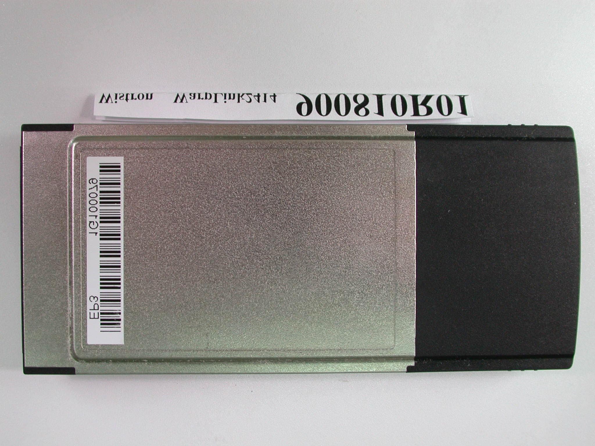
Click to zoom
Application Details
- Equipment Class
- DTS - Digital Transmission System
- Date of Grant
- Sep 30, 2001
- Application Purpose
- Original Equipment
- Date of Application
- Sep 30, 2001
- Equipment Note
- WLAN PCMCIA Card
- Frequency Range
- 2412.00000000 - 2462.00000000
- Company
- Wistron NeWeb Corporation
- Country
- Taiwan
Documents & Files
Document Text
Text extracted from the exhibit documents filed with the FCC. Open a document above to read the original.
Users Manual
WarpLink 2414 User Manual IEEE 802.11b WLAN PCMCIA Card Version 1.0 Aug. 2001 Wistron NeWeb Corporation TEL:886-3-5428000 Web: www.acerneweb.com 1 Table of Contents 1. Welcome .................................................................................................................3 1.1 Kit Contents ....................................................................................................................... 4 1.2 Main Features of IEEE802.11b WLAN PC Card.............................................................. 5 1.3 Wireless Networking Scenarios......................................................................................... 6 1.4 Advantages for Using a Wireless Network........................................................................ 8 2. Quick Start Guide ..................................................................................................9 3. Step-by-Step Installation Guide..........................................................................12 3.1 Over View........................................................................................................................ 12 3.2 Install the IEEE802.11b WLAN Utility/ Driver .............................................................. 13 3.3 Install the PCMCIA Card ................................................................................................ 24 3.4 Utility Start-up Configuration.......................................................................................... 25 3.4.1 Set Basic Parameters.................................................................................................. 26 3.4.2 Advanced Settings ..................................................................................................... 31 4 Using Your IEEE802.11b WLAN PC Card and Utility ....................................35 4.1 Using Your IEEE802.11b WLAN PC Card .................................................................... 35 4.1.1 Radio Antenna ........................................................................................................... 35 4.1.2 Maintaining Your PC Card........................................................................................ 35 4.1.3 Disconnect the Wireless Communications ................................................................ 36 4.2 Using the Utility .............................................................................................................. 41 4.2.1 LAN Status ................................................................................................................ 41 4.2.2 Link Information........................................................................................................ 43 4.2.3 Site Survey................................................................................................................. 43 4.2.4 Diagnostic .................................................................................................................. 44 4.2.5 About ......................................................................................................................... 44 5. Networking Applications.....................................................................................45 5.1 File Sharing in Microsoft Windows 98SE....................................................................... 45 5.2 Printer Sharing in Windows 98SE................................................................................... 48 5.3 Using the shared folder ....................................................................................................50 5.4 Using the shared network printer..................................................................................... 51 6. Specifications ......................................................................................................52 6.1 Physical Specifications ....................................................................................................52 6.2 Networking Compliant Standards ................................................................................... 52 6.3 Available Channels in Each Country/ Area ..................................................................... 53 2 6.4 Operating Specifications.................................................................................................. 54 7. Troubleshooting...................................................................................................56 7.1 Check the Various Properties of the Card ....................................................................... 56 7.2 Microsoft Networking Checklist ..................................................................................... 59 7.3 Others............................................................................................................................... 62 FCC Class B Radio Frequency ...............................................................................64 3 1. Welcome Thank you for purchasing the IEEE802.11b WLAN PC Card, the easiest way to wireless networking. As our product is interoperable with other IEEE802.11b compliant products (even if they are made by other manufacturers), it offers you great flexibility and freedom to build your own ideal wireless LAN. You can connect your PC/notebook to an access point wirelessly to share a “connected” environment, such as your local area network. This User’s Guide introduces to you the common configurations of IEEE802.11b WLAN PC Card and leads you through the installation step by step. Please read this manual to become familiar with this IEEE802.11b WLAN PC Card and its applications. This manual contains detailed instructions in the operation of this product. Please keep this manual for future reference. 4 1.1 Kit Contents The IEEE802.11b WLAN PC Card package includes the following items: A. 1 PCMCIA Card B. 1 CD including: IEEE802.11b WLAN Utility & Driver software, Acrobat Reader and use…
Text truncated - open the document above for the full version.
Users Manual
9 2. Quick Start Guide If you are familiar with computer networking, this Quick Start Guide is the fastest way for you to establish your wireless network. If you need more information than this Quick Start Guide can provide you, the next chapter, Step-by-Step Installation Guide, will run you through the necessary steps. 1. 2. 3. Insert the CD provided into your CD ROM drive and it will automatically start the setup program. Follow the installation wizard to complete the software installation process; restart your notebook when the process is finished. Insert the IEEE802.11b WLAN PC Card into the PCMCIA slot of your notebook after restarting the notebook. 10 4. 5. 6. The operating system will detect the IEEE802.11b WLAN PC Card and install the proper drivers automatically. You may check the status by the following procedures: My Computer#Control Panel#System#Device Manager#Network Adapters Double click the WLAN icon on the desktop after the installation, and you will find a small icon in the toolbar at the bottom of the screen. This icon indicates the communication status: if it is green, it means well connected— please go on to step 8; if it is red, it means connection failed— please go on to step 7. 11 7. 8. 9. Double click the status icon and then click “LAN Status” tab. Please push the “rescan” button and then return to the main screen. If the status turns green, then go on to step 8. If it remains red, please repeat the installation process from step 1. Double click the status icon and then select the “Setting” tab. Please choose “Infrastructure” mode and type a name in the SSID column (This SSID should be the same as the network ID of your Access point). Or, if you would like to connect with other stations without an Access Point, please select “802.11 Ad Hoc” mode or “Ad-Hoc” mode (we recommend “802.11 Ad Hoc” for compatibility with all IEEE802.11 protocol compliant products). Click “Apply” and enjoy surfing the Internet. 12 3. Step-by-Step Installation Guide 3.1 Over View This chapter introduces you to a step-by-step process in installing your IEEE802.11b WLAN PC Card and its driver. To establish your wireless network connection, the following steps should be executed. A. Install the software by using the installation CD. (See 3.2) B. Install (insert) the wireless LAN card. (See 3.3) C. Set basic parameters. (See 3.4) D. Install the required network protocols to communicate with your network—mainly, the TCP/IP protocol and NetBEUI Protocol. As this product is designed to run under Microsoft Windows compatible operation systems*, it is recommended that people who are familiar with the installation procedures for network operating systems under Microsoft Windows operate the installation process. *Compatible Microsoft Windows operation systems include Windows 98SE, Windows Me, Windows NT4.0 with Service Pack 3 or later and Windows 2000. 13 3.2 Install the IEEE802.11b WLAN Utility/ Driver Please install the IEEE802.11b WLAN Utility/Driver first before inserting the IEEE802.11b WLAN PCMCIA Card. Insert the IEEE802.11b WLAN installation CD into your CD-ROM drive. The setup program will then automatically start. You can select the following applications you want to install. A. Install IEEE802.11b Driver and Utility B. Browse User Manual Make sure you have selected “Install IEEE802.11b Driver and Utility”; then click “Next”. 14 1. When the “Welcome” screen appears click on ”Next”. 2. Please carefully read the “Software License Agreement“. If you accept the contract, click “Yes“ to move to the next screen. If not, click “No“ to exit. 15 3. The default destination folder is displayed in the setup dialog box. To change the default folder you can click “Browse” to set the destination folder. Click “Next” to go to the next screen. 16 4. Select the Program Folder for IEEE802.11b WLAN Utility and click “Next”. 5. You will be asked if you want to add an IEEE802.11b WLAN Utility shortcut to your desktop. Click “Yes”. 6. The user manual is published in Portable Document Format (PDF). If Acrobat Reader does not exist in your system, the following message will appear. Please follow the instructions to complete the Acrobat Reader 4.05 installation. 17 7. Once the Acrobat Reader installation has been completed, the following page will appear reminding you to install the Microsoft network protocols for your IEEE802.11b WLAN to work properly. A. If you know the required network protocols are installed on your system, click “No” and go to Step 9. B. If you are unsure, click “Yes” and refer to Section 7.2 for the Microsoft Network Checklist and go to Step 8. 8. The “Network“ page will appear if you click on “Yes” in the previous screen. You can add the necessary protocols by clicking “Add” button. Please refer to Section7.2 Microsoft Networking Checklist for the proper items to install. After adding the protocols, you will be prompted to reboot the system—please click “No” and go to Step 9. 18 9. The Driver and Help files will be copied to the system. Wait for the setup program to finish the IEEE802.11b WLAN installation. Then select “Yes” and click “Finish“ to complete the installation. It is recommended you close other applications before rebooting your system. 10. You have finished installing the software portion of the IEEE802.11b WLAN PC Card, please refer to Section 3.3 and follow the rest of those installations to complete the entire installation process. 19 Additional Note for Windows NT4.0 The installation procedure under Windows NT4.0 will be slightly different from the previous Windows 98SE installation shown. 1. Click “OK” and system will auto-select the I/O address and the IRQ, and remind you to choose the unused I/O address and IRQ from Windows NT Diagnosis to prevent system resource conflict. 2. If the Ndis 3.0 packet driver already exists in your system, the setup message will be prompted as follows, just click “OK”. 3. A prompt of networking setting will appear as follows. It’s the same as…
Text truncated - open the document above for the full version.
Users Manual
30 B. Ad Hoc Mode Please follow the procedures below to set the “Ad Hoc” Mode: 1. Select the “Setting” tab. 2. Select the Network Type as ”Ad Hoc”. 3. Select the correct channel. (The channel of all computers in one workgroup must be the same.) 4. Press the “Apply” button. $ Channel shows radio channel numbers used for networking. Channel number must be the same between stations so computers can communicate in the same local LAN. It can be changed only under the Ad Hoc Mode. Please refer to the following table. Country Channel Range USA/Canada 1~11 Most of Europe/Australia 1~13 France 10~13 Japan 1~13 or 14 Spain 10~11 31 3.4.2 Advanced Settings Click the “Advance” button in the Setting page and then the following advanced setting for your IEEE802.11b WLAN PC card will appear. Regarding the transmission rate, there are four options: A. Fully Auto (Default) B. Fixed 11Mbps C. Fixed 5.5Mbps D. Auto 1 or 2 Mbps You may select and change transmission rate by clicking the pull-down button. If you enable the “Power Saving” mode, the PC card can work with low power consumption but the throughput may slow down. 32 3.4.2.1 Encryption Function You may enhance the security of your network by enabling the “Encryption” function. The WEP Required Mode enables you to define the encryption keys that your IEEE802.11b PCMCIA should use. ! Caution: If you wish to enable the “Encryption” function, you must enable this function for all computers of your network, and the WEP key needs to be the same for all IEEE802.11b stations. Follow the steps below to set your WEP Required Mode: (1) Select one mode by clicking the pull-down button in the WEP Required Mode frame. Set the WEP key in your PC card by selecting one of the following modes: A. Auto Generate 64 bits B. Auto Generate 128 bits C. Manual Generate 64 bits D. Manual Generate 128 bits (2) If you select “Auto Generate 64 bits” or “Auto Generate 128 bits” mode, type “Pass” and the WEP key will be automatically generated in Key1 box. 33 a. Auto Generate 64 bits . b. Auto Generate 128 bits 34 (3) If you select “Manual Generate 64 bits” mode, you can type 10 alphanumeric characters (within the range 0~9 and a~f) as the WEP key manually into any key box. (4) If you select “Manual Generate 128 bits” mode, you can type 26 alphanumeric characters (within the range 0~9 and a~f) as the WEP key manually only into the key1 box. (5) Press the “Apply” button after you finish the above setting. 35 4 Using Your IEEE802.11b WLAN PC Card and Utility 4.1 Using Your IEEE802.11b WLAN PC Card 4.1.1 Radio Antenna The embedded radio antenna of your IEEE802.11b WLAN PC Card performs best in an open environment with as few obstacles as possible. ! To achieve the maximum range for wireless communications do not cover the card with objects such as books or thick stacks of paper. 4.1.2 Maintaining Your PC Card To clean the PC Card, gently wipe it with a soft (damp) cloth. ! CAUTION: To avoid damage to the PC Card do not use abrasive materials, or rinse the card with liquids. 36 4.1.3 Disconnect the Wireless Communications 4.1.3.1 Remove Your PC Card If you do not need the wireless connectivity of your IEEE802.11b PCMCIA Card, you can follow the procedures mentioned below to remove the PC Card from its slot. ! CAUTION: ! When removing the IEEE802.11b PCMCIA Card you will lose your connection to the network. Prior to removing the PC Card, make sure you have closed all files and network applications (such as e-mail). ! You are advised to always disable the PC Card prior to removing the card from the PC Card slot, or the system may be hurt seriously. To stop using the IEEE802.11b PCMCIA Card: 1. Double click the “My Computer” icon. 2. Double click the “Control Panel” icon and then select the “PC Card” icon. 3. Select the IEEE802.11b PC Card and click “Stop” icon. 37 4. Wait a few seconds until the operating system displays a pop-up message to indicate you can safely remove the PC Card. 38 4.1.3.2 Uninstall the IEEE802.11b WLAN Utility/ Driver 1. To exit the IEEE802.11b WLAN Utility, right click on the Utility icon in the task bar and select “Exit”. 2. Click on the “Start Manu” and select the items in sequence as follows: Program#IEEE 802.11b WLAN Utility#IEEE 802.11b Uninstallation 3. You will be asked if you want to uninstall the IEEE802.11b WLAN Utility and all of its components. Click “Yes“ to start to uninstall or click “No“ to exit. 39 4. Now the uninstallation is completed. Please click “Finish“. 40 Additional Note for Windows 2000 The following items should be noted: 1. Please do not remove your PC card unless the IEEE802.11b WLAN un-installation is completed. 2. Make sure to exit the IEEE802.11b WLAN Utility before uninstalling. 3. To uninstall the IEEE802.11b WLAN Utility and Driver, the system will prompt you to execute the “Device Manager” to remove the IEEE802.11b WLAN PC Card, and then click “OK”. 4. The system will give you a prompt as below while waiting for the “Device Manager”. Follow the instruction to uninstall IEEE802.11b WLAN adapter. 41 4.2 Using the Utility 4.2.1 LAN Status If you want to know the connecting status in Infrastructure Mode or 802.11Ad Hoc Mode, choose LAN Status tab in IEEE802.11b WLAN Utility window. 1. Infrastructure Mode: ! The SSID and MAC of the Access Point, which your computer connects to, will appear in the screen if you choose the Infrastructure Mode. ! Double click the Access Point SSID (under the Infrastructure Mode) to access to the Microsoft Network Neighborhood folder to find other on-line computers. ! You can see the status of the Link Quality and Signal Strength under the LAN Status page. 42 2. 802.11 Ad Hoc Mode / Ad Hoc Mode: ! The Station Name and MAC Address of your station will appear if you choose the 802.11Ad Hoc Mode (or Ad Hoc mode). ! Double click the right name to display the content of your computer or double click Network Neighbors to access to the Microsoft Network Neighborhood folder to find other on-line computers. ! …
Text truncated - open the document above for the full version.
Cover Letter(s)
Federal Communications Commission Authorization and Evaluation Division Confidentiality Request Pursuant to Sections 0.457 and 0.459 of the Commission’s Rules, the Applicant hereby requests confidential treatment of information accompanying this Application as outlined below: Schematics Block Diagram Operational Descriptions The above materials contain trade secrets and proprietary information not customarily released to the public. The public disclosure of these matters might be harmful to the Applicant and provide unjustified benefits to its competitors. The Applicant understands that pursuant to Rule 0.457, disclosure of this Application and all accompanying documentation will not be made before the date of the Grant for this application. Sincerely, Robin Wu/ Engineer Acer NeWeb Corp. 5F, No. 16, Sec. 2, Ching Kuo Rd., Hsinchu, Taiwan, R.O.C. Tel: +886 3 5428 000 Fax: +886 3 5420098 FCC ID: NKR2414
Cover Letter(s)
POWER OF ATTORNEY To whom it may concern: We, the undersigned, Acer NeWeb Corp. ,hereby authorize Advance Data Technology Corporation (ADT) of Taiwan to act on our behalf in all matters relating to all processes required in the FCC Part 15C approval and any communication needed with the national authority. Any and all acts carried out by ADT on our behalf shall have the same effects as acts of our own. If you have any questions regarding the authorization, please don’t hesitate to contact us. Thank you! Sincerely yours, ------------------------------------------------------------------- Robin Wu/ Engineer Acer NeWeb Corp. Tel: +886 3 5428 000 Fax: +886 3 5420 098 e-mail: [email protected] Acer NeWeb Corp. 5F, No. 16, Sec. 2, Ching Kuo Rd., Hsinchu 300,Taiwan, R.O.C Tel: +886 3 5428 000 Fax: +886 3 5420 098
External Photos
Page 1 ANNEX PHOTOGRAPHS OF EUT Page 2
ID Label/Location Info
Label & label location for WarpLink 2414 front side viewBack side view
Internal Photos
Page 3 Page 4 Page 5
Test Report
FCC ID: NKR2414 Report No.: RF900810R01 1 Issued: August 29, 2001 FCC TEST REPORT REPORT NO.: RF900810R01 MODEL NO.: WarpLink2414 (for Wistron) CWA700 (for Alexon) RECEIVED: August 10, 2001 TESTED: August 23~ August 27, 2001 APPLICANT: Acer NeWeb Corporation ADDRESS: 5F, NO.16 SEC 2, CHING KUO ROAD, HSINCHU 300, TAIWAN, R.O.C. ISSUED BY: Advance Data Technology Corporation LAB LOCATION: 47 14th Lin, Chiapau Tsun, Linko, Taipei, Taiwan, R.O.C. This test report consists of 49 pages in total. It may be duplicated completely for legal use with the approval of the applicant. It should not be reproduced except in full, without the written approval of our laboratory. The client should not use it to claim product endorsement by CNLA, NVLAP or any government agencies. The test results in the report only apply to the tested sample. 0528 Lab Code: 200102-0 FCC ID: NKR2414 Report No.: RF900810R01 2 Issued: August 29, 2001 Table of Contents 1CERTIFICATION ........................................................................................... 4 2SUMMARY OF TEST RESULTS ................................................................... 5 3GENERAL INFORMATION............................................................................ 6 3.1GENERAL DESCRIPTION OF EUT.............................................................. 6 3.2DESCRIPTION OF TEST MODES ................................................................ 7 3.3GENERAL DESCRIPTION OF APPLIED STANDARDS ............................... 7 3.4DESCRIPTION OF SUPPORT UNITS .......................................................... 8 4TEST TYPES AND RESULTS ....................................................................... 9 4.1CONDUCTED EMISSION MEASUREMENT ................................................ 9 4.1.1LIMITS OF CONDUCTED EMISSION MEASUREMENT .............................. 9 4.1.2TEST INSTRUMENTS................................................................................... 9 4.1.3TEST PROCEDURES ................................................................................. 10 4.1.4TEST SETUP .............................................................................................. 10 4.1.5EUT OPERATING CONDITIONS ................................................................ 11 4.1.6TEST RESULTS .......................................................................................... 12 4.2RADIATED EMISSION MEASUREMENT ................................................... 18 4.2.1LIMITS OF RADIATED EMISSION MEASUREMENT ................................. 18 4.2.2TEST INSTRUMENTS................................................................................. 19 4.2.3TEST PROCEDURES ................................................................................. 20 4.2.4TEST SETUP .............................................................................................. 21 4.2.5EUT OPERATING CONDITIONS ................................................................ 21 4.2.6TEST RESULTS .......................................................................................... 22 4.36DB BANDWIDTH MEASUREMENT .......................................................... 27 4.3.1LIMITS OF 6dB BANDWIDTH MEASUREMENT ........................................ 27 4.3.2TEST INSTRUMENTS................................................................................. 27 4.3.3TEST PROCEDURE.................................................................................... 28 4.3.4TEST SETUP .............................................................................................. 28 4.3.5EUT OPERATING CONDITIONS ................................................................ 28 4.3.6TEST RESULTS .......................................................................................... 29 4.4MAXIMUM PEAK OUTPUT POWER .......................................................... 33 4.4.1LIMITS OF MAXIMUM PEAK OUTPUT POWER MEASUREMENT ........... 33 4.4.2TEST INSTRUMENTS................................................................................. 33 4.4.3TEST PROCEDURES ................................................................................. 34 4.4.4TEST SETUP .............................................................................................. 34 4.4.5EUT OPERATING CONDITIONS ................................................................ 34 FCC ID: NKR2414 Report No.: RF900810R01 3 Issued: August 29, 2001 4.4.6TEST RESULTS .......................................................................................... 35 4.5POWER SPECTRAL DENSITY MEASUREMENT ...................................... 36 4.5.1LIMITS OF POWER SPECTRAL DENSITY MEASUREMENT ................... 36 4.5.2TEST INSTRUMENTS................................................................................. 36 4.5.3TEST PROCEDURE.................................................................................... 37 4.5.4TEST SETUP .............................................................................................. 37 4.5.5EUT OPERATING CONDITIONS ................................................................ 37 4.5.6TEST RESULTS .......................................................................................... 38 4.6BAND EDGES MEASUREMENT ................................................................ 42 4.6.1LIMITS OF BAND EDGES MEASUREMENT .............................................. 42 4.6.2TEST INSTRUMENTS................................................................................. 42 4.6.3TEST PROCEDURE.................................................................................... 42 4.6.4EUT OPERATING CONDITION .................................................................. 43 4.6.5TEST RESULTS .......................................................................................... 43 4.7ANTENNA REQUIREMENT ........................................................................ 46 4.7.1STANDARD APPLIC…
Text truncated - open the document above for the full version.
Test Setup Photos
FCC ID: NKR2414 Report No.: RF900810R01 47 Issued: August 29, 2001 5 PHOTOGRAPHS OF THE TEST CONFIGURATION CONDUCTED EMISSION TEST FCC ID: NKR2414 Report No.: RF900810R01 48 Issued: August 29, 2001 RADIATED EMISSION TEST
Contact Information
Applicant
William Su(Senior Director / System Engineering dept.)
Technical Contact
Advance Data Technology CorporationAlan Lane
[email protected]+886 3 327 0910
13-1, Lane 19, WenShan 3rd St · Taoyuan · Taiwan
Test Firm
Bureau Veritas CPS (H.K.) Ltd. Taoyuan BranchRichard Chen
Technical Specifications
| # | Rule Parts | Frequency Range | Power Output |
|---|---|---|---|
| 1 | 15C | 2.41 GHz - 2.46 GHz | 64.00 mW |
Other Applications from Wistron NeWeb Corporation
NKR-ATTCGW453
Aug 25, 2026Enterprise product
Equipment Class
NII - Unlicensed National Information Infrastructure TXNKR-LS06B
Aug 24, 2026Touchscreen
Equipment Class
NII - Unlicensed National Information Infrastructure TXNKR-DWSZW
Aug 10, 2026Door/Window Sensor
Equipment Class
DXX - Part 15 Low Power Communication Device TransmitterNKR-TELE2
Jun 26, 2026TELE2
Equipment Class
NII - Unlicensed National Information Infrastructure TXNKR-VMC-SA525MAX
Jun 05, 2026NAD (Network Access Device)
Equipment Class
CXX - Communications Rcvr for use w/ licensed Tx and CBs