NKRAP200IEEE 802.11b WLAN Access Point
Wistron NeWeb Corporation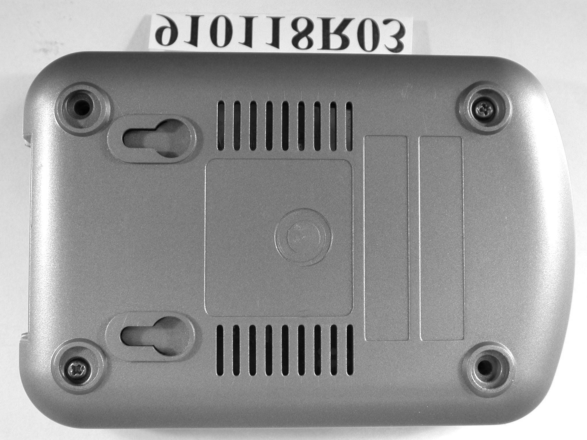
Click to zoom
Application Details
- Equipment Class
- DTS - Digital Transmission System
- Date of Grant
- Apr 24, 2002
- Application Purpose
- Original Equipment
- Date of Application
- Apr 24, 2002
- Equipment Note
- IEEE 802.11b WLAN Access Point
- Frequency Range
- 2412.00000000 - 2462.00000000
- Company
- Wistron NeWeb Corporation
- Country
- Taiwan
Documents & Files
Document Text
Text extracted from the exhibit documents filed with the FCC. Open a document above to read the original.
Users Manual
1 Your Installation Guide to Access Point Version 2.1 – January 2002 2 Copyright Statement No part of this publication may be reproduced, stored in a retrieval system, or transmitted in any form or by any means, whether electronic, mechanical, photocopying, recording or otherwise without the prior writing of the publisher. Windows 95/98 and Windows 2000 are trademarks of Microsoft Corp. Pentium is trademark of Intel. All copyright reserved. 1 2 3 Table of Contents Table of Contents3 Regulatory information4 1. Welcome5 1.1Advantages for Using Wireless Network5 1.2About Access Point6 1.3 Verifying kit contents6 1.4 Wireless Adapter6 1.5 System Interoperatability6 2. Step-by-Step Installation Guide 7 3. Access Point SNMP Manager8 3.1About Access Point SNMP Manager8 3.2 Install SNMP Manager9 3.3 Uninstall SNMP Manager13 4. Using Access Point SNMP Manager14 4.1 Connecting to Access Point14 4.2 Configuring the Access Point 16 4.2.1 Setting the IP address of the Access Point16 4.2.2 File menu16 4.2.3 Setup menu17 4.2.4 Commands menu22 4.2.5 Info menu23 4.2.6 Traps menu27 4.2.7 Network menu27 4.2.8 Window menu27 4.2.9 Help menu27 5. Glossary28 6. Technical Specifications30 4 Regulatory Information The manufacturer is not responsible for any radio or television interference caused by unauthorized modification of this device or the substitution or attachment of connecting cables and equipment other than specified. The correction of interference caused by such unauthorized modification, substitution or attachment will be the responsibility of the user. Built-in antennas, whether installed indoors or out, should be installed only by experienced antenna installation professionals who are familiar with local building and safety codes and, wherever applicable, are licensed by the appropriate government regulatory authorities. USA – Federal Communications Commission (FCC) This equipment has been tested and found to comply with the limits for Class B Digital Devices, pursuant to Part 15 of the FCC Rules. These limits are designed to provide reasonable protection against harmful interference in a residential installation. This equipment generates, uses and can radiate radio frequency energy and, if not installed and used in accordance with the instruction, may cause harmful interference to radio communications, However, there is no guarantee that interference will not occur in a particular installation. If this equipment does cause harmful interference to radio or television reception, which can be determined by turning the equipment off and on, the user is encouraged to try to correct the interference by one or more of the following measures: - Reorient or relocate the receiving antenna - Increase the separation between the equipment and the receiver - Connect the equipment into an outlet on a circuit different from that to - Which the receiver is connected. - Consult the dealer or an experienced radio/TV technician for help. Canada – Industry Canada (IC) This class B digital apparatus meets all requirements of the Canadian Interference Causing Equipment Regulations. 5 1. Welcome Thank you for purchasing Access Point! Access Point is easy to install and easy to operate—in no time you will have your own wireless network. This guide will lead you through the installation process in detail. Please read this manual carefully and keep it for future reference. You need to have a basic knowledge of installation procedures for network operating systems under Microsoft Windows 95 (or up) and Windows NT. 1.1Advantages for Using Wireless Network Advantages for Using a Wireless Network: - For hard to wire areas: Access Point provides access to network services in areas otherwise hard or expensive to wire, such as historic buildings with asbestos and classrooms. - Flexible workgroups: Lower total cost of ownership for workspaces that are frequently reconfigured. - Networked conference rooms: users can access the network as they move from meeting to meeting, can get up-to-date access to information and can communicate while ‘on the go’. - Easy Network: with quick network setup and collaboration software, on site consultants and small workgroups increase efficiency and productivity. - Branch office networking: provides an easy to install, use and maintain network for a remote or sales office. - Campus-wide network mobility: roaming capabilities allow enterprises to set up easy-to-use wireless networks that cover the entire campus transparently. 6 1.2About Access Point The Access Point is a modular unit with an integrated Ethernet interface that enables you to use your Access Point with your adaptors. The Antennas are built-in which creates further wireless atmosphere and a cleaner look. The Access Point is a wired to wireless bridge that you can use to connect wireless cells to one another or to a wired (Ethernet) Local Area Network. The Access Point can serve mobile wireless clients roaming between various locations within network premises. 1.3Kit Contents The contents of the box should include the following items: - User’s Guide - Quick Start Guide - Access Point (with the MAC-address in the back) - Power Line - CD: containing Installation Driver and SNMP Manager Software If you find any incorrect, missing or damaged parts, please contact the vendor immediately. 1.4Wireless Adaptor Adaptor comes in separate packages. It is a wireless network adapter, that allows sharing of Internet access and peripherals through access point. Adaptor comes in two types: PC Card and USB Adapter. PC Card is for the use of notebook only, whereas USB is compatible for both computer and notebook. 1.5System Interoperatability Access Point is able to integrate with other brand’s wireless network communication systems. 7 2. Step-by-Step Installation Guide This section helps you with the installation of the Access Point. Please follow the instructions on how to install your Access Point: 1. Mount the Access Point firmly to the wall on the des…
Text truncated - open the document above for the full version.
Cover Letter(s)
Federal Communications Commission Authorization and Evaluation Division Confidentiality Request Pursuant to Sections 0.457 and 0.459 of the Commission’s Rules, the Applicant hereby requests confidential treatment of information accompanying this Application as outlined below: Schematics Block Diagram The above materials contain trade secrets and proprietary information not customarily released to the public. The public disclosure of these matters might be harmful to the Applicant and provide unjustified benefits to its competitors. The Applicant understands that pursuant to Rule 0.457, disclosure of this Application and all accompanying documentation will not be made before the date of the Grant for this application. Sincerely, 2002/1/23 Robin Wu / manager Engineer Wistron NeWeb Corp. No. 10-1, Li-hsin Road I, Science-based Industrial Park, Hsinchu 300, Taiwan, R.O.C Tel: +886 3 6667799 Fax: +886 3 6667711 FCC ID:NKRAP200
Cover Letter(s)
Inform Letter Dear Customer, According to FCC’s regulation, the following Declaration of Conformity has to be made by a company located in USA. They are: This device has been confirmed to be in compliance with the requirements of ANSI C63.4 & FCC part 15 regulations. The test result has been shown in the ADT test report with number RF910118R03 And this compliance is subject to the following two conditions: (1) This device may not cause harmful interference and, (2) This device must accept any interference received, including interference that may cause undesired operation. This declaration can be a separate sheet and be sure that the following message will be also included in this declaration: 1) Product name, model name and trade name. 2) Company name, and address of the one who is responsible for this declaration. 3) Name, title, telephone and fax number as well as the signature of the contact person. Thanks for your attention. No. 10-1, Li-hsin Road I, Science-based Industrial Park, Hsinchu 300, Taiwan, TEL: +886-3-6667799 FAX: +886-3-6667711
Cover Letter(s)
POWER OF ATTORNEY To whom it may concern: We, the undersigned, Wistron NeWeb Corp. hereby authorize Advance Data Technology Corp. (ADT) of Taiwan to act on our behalf in all matters relating to all processes required in the FCC Part 15C and any communication needed with the national authority. Any and all acts carried out by ADT on our behalf shall have the same effects as acts of our own. If you have any questions regarding the authorization, please don’t hesitate to contact us. Thank you! Sincerely yours, ------------------------------------------------------------------- Robin Wu/ Manager Engineer Wistron NeWeb Corp. Tel: +886 3 6667799-6631 Fax: +886 3 6667711 e-mail: [email protected] Wistron NeWeb Corp. No. 10-1, Li-hsin Road I, Science-based Industrial Park, Hsinchu 300, Taiwan, R.O.C Tel: 886 3 6667799 Fax: 886 3 6667711 23-Jan-02
External Photos
Page 1 ANNEX PHOTOGRAPHS OF EUT Page 2 Page 3 Page 4
ID Label/Location Info
Label & label location for AP-200 Back side view
Operational Description
FCC ID: NKRAP200 ADT No.910118R03 Operational Description The transmitter of the EUT is powered by power adapter and connected with notebook through RJ45 port. The antenna used in this product is Integral Antenna. There is no antenna connector. Under normal use condition, the user has to keep at least 20cm separation distance between radiator and the body of the user. The other instruction, please have a look at the users manual. DSSS Information This device is Direct Sequence Spread Spectrum, the data is mixed by pseudorandom code which is an orthogonal code. The mixed data is digital modulated by BPSK and QPSK technique depends on the data rates. The CCK coding is applied for increasing the data rate, and also the processing gain will be increased. The bit rates are 1,2,5.5,11,22Mbps.
RF Exposure Info
FCC ID: NKRAP200 ADT No.: 910118R03 FCC TEST REPORT REPORT NO.: RF910118R03 MODEL NO.: AP-200 ACCORDING: FCC Guidelines for Human Exposure IEEE C95.1 APPLICANT:Wistron NeWeb Corporation ADDRESS: No. 10-1, Li-hsin Road I, Science-based Industrial Park, Hsinchu 300, Taiwan ISSUED BY:Advance Data Technology Corporation LAB LOCATION:47 14th Lin, Chiapau Tsun, Linko, Taipei, Taiwan, R.O.C. ILAC MRA 0528 Lab Code: 200102-0 FCC ID: NKRAP200 ADT No.: 910118R03 RF Exposure Measurement 1. Introduction 2.4 GHz frequency band is regarded specially as a dangerous band for its heating harmfulness to the human body. That’s why microwave oven is operating in this frequency band. The manufacturer whose product is working in this frequency band is obligatory to prove the harmfulness of his product. In this document, we try to prove the safety of radiation harmfulness to the human body for our product. The limit for Maximum Permissible Exposure (MPE) specified in FCC 1.1310 is followed. The Gain of the antenna used in this product is measured in a Fully Anechoic Chamber (FAC) calibrated for antenna measurement in ADT, and also the maximum total power input to the antenna is measured. Through the Friis transmission formula and the maximum gain of the antenna, we can calculate the distance, away from the product, where the limit of MPE is reached. Although the Friis transmission formula is a far field assumption, the calculated result of that is an over-prediction for near field power density. We will take that as the worst case to specify the safety range. 2. RF Exposure Limit According to FCC 1.1310: The criteria listed in the following table shall be used to evaluate the environmental impact of human exposure to radio-frequency (RF) radiation as specified in 1.1307(b) LIMITS FOR MAXIMUM PERMISSIBLE EXPOSURE (MPE) Frequency Range (MHz) Electric Field Strength (V/m) Magnetic Field Strength (A/m) Power Density (mW/cm 2 ) Average Time (minutes) (A)Limits For Occupational / Control Exposures 300-1500......F/3006 1500-100,000......56 (B)Limits For General Population / Uncontrolled Exposure 300-1500......F/15006 1500-100,000......1.030 F = Frequency in MHz FCC ID: NKRAP200 ADT No.: 910118R03 3. Friis Formula Friis transmission formula : Pd = (Pout*G) / (4*pi*r 2 ) where Pd = power density in mW/cm 2 Pout = output power to antenna in mW G = gain of antenna in linear scale Pi = 3.1416 R = distance between observation point and center of the radiator in cm Pd is the limit of MPE, 1 mW/cm 2 . If we know the maximum Gain of the antenna and the total power input to the antenna, through the calculation, we will know the distance r where the MPE limit is reached. Ref. : David K. Cheng, Field and Wave Electromagnetics, Second Edition, Page 640, Eq. (11-133). 4 EUT Operating condition The software provided by Manufacturer enabled the EUT to transmit and receive data at lowest, middle and highest channel individually. 5 Climate Condition The temperature and related humidity: 14 deg. C and 65 % RH 6. Classification This device is not fixed inside the host equipment, it is connected with host through wire. So it is easy to be re-located in the place where at least 20 cm far away from the body of the user. Warning statement to the user for keeping at least 20cm or more separation distance with the antenna should be included in users manual. So, this device is classified as Mobile Device. FCC ID: NKRAP200 ADT No.: 910118R03 7 Test Results 7.1 Antenna Gain The maximum Gain measured in Fully Anechoic Chamber is -1dBi or 0.79 (numeric). 7.2 Output Power Into Antenna & RF Exposure Distance : CHANNEL CHANNEL FREQUENCY (MHz) OUTPUT POWER TO ANTENNA (mW) MINIMUM ALLOWABLE DISTANCE ( r ) FROM SKIN (Centi-Meter) 1241238.111.55 6243739.541.58 11246230.551.39 The minimum allowable distance is very close to the enclosure of the antenna. So, the user has no need to worry about the harmfulness of radiation. But it is recommended to always keep, at least, 20 cm separation distance with the antenna.
Test Report
FCC ID: NKRAP200 Report No.: RF910118R03 1 Issued: April 16, 2002 FCC TEST REPORT REPORT NO.: RF910118R03 MODEL NO.: AP-200 RECEIVED: Jan. 17, 2002 TESTED: April 8 ~ 9, 2002 APPLICANT: Wistron NeWeb Corp. ADDRESS: No. 10-1, Li-hsin Road I, Science-based Industrial Park, Hsinchu 300, Taiwan ISSUED BY: Advance Data Technology Corporation LAB LOCATION: 47 14 th Lin, Chiapau Tsun, Linko, Taipei, Taiwan, R.O.C. This test report consists of 49 pages in total. It may be duplicated completely for legal use with the approval of the applicant. It should not be reproduced except in full, without the written approval of our laboratory. The client should not use it to claim product endorsement by CNLA, NVLAP or any government agencies. The test results in the report only apply to the tested sample. 0528 ILAC MRA Lab Code: 200102-0 FCC ID: NKRAP200 Report No.: RF910118R03 2 Issued: April 16, 2002 Table of Contents 1CERTIFICATION ...........................................................................................4 2SUMMARY OF TEST RESULTS...................................................................5 3GENERAL INFORMATION ...........................................................................6 3.1GENERAL DESCRIPTION OF EUT..............................................................6 3.2DESCRIPTION OF TEST MODES................................................................7 3.3GENERAL DESCRIPTION OF APPLIED STANDARDS ...............................7 3.4DESCRIPTION OF SUPPORT UNITS..........................................................8 4TEST TYPES AND RESULTS.......................................................................9 4.1CONDUCTED EMISSION MEASUREMENT ................................................9 4.1.1LIMITS OF CONDUCTED EMISSION MEASUREMENT.................................................... 9 4.1.2TEST INSTRUMENTS....................................................................................................... 9 4.1.3TEST PROCEDURES..................................................................................................... 10 4.1.4TEST SETUP .................................................................................................................. 10 4.1.5EUT OPERATING CONDITIONS..................................................................................... 11 4.1.6TEST RESULTS ..............................................................................................................12 4.2RADIATED EMISSION MEASUREMENT ...................................................18 4.2.1LIMITS OF RADIATED EMISSION MEASUREMENT ...................................................... 18 4.2.2TEST INSTRUMENTS..................................................................................................... 19 4.2.3TEST PROCEDURES..................................................................................................... 20 4.2.4TEST SETUP .................................................................................................................. 21 4.2.5EUT OPERATING CONDITIONS..................................................................................... 21 4.2.6TEST RESULTS ..............................................................................................................22 4.36dB BANDWIDTH MEASUREMENT ..........................................................27 4.3.1LIMITS OF 6dB BANDWIDTH MEASUREMENT.............................................................. 27 4.3.2TEST INSTRUMENTS..................................................................................................... 27 4.3.3TEST PROCEDURE........................................................................................................ 28 4.3.4TEST SETUP .................................................................................................................. 28 4.3.5EUT OPERATING CONDITIONS..................................................................................... 28 4.3.6TEST RESULTS ..............................................................................................................29 4.4MAXIMUM PEAK OUTPUT POWER ..........................................................33 4.4.1LIMITS OF MAXIMUM PEAK OUTPUT POWER MEASUREMENT ................................. 33 4.4.2INSTRUMENTS...............................................................................................................33 4.4.3TEST PROCEDURES..................................................................................................... 34 4.4.4TEST SETUP .................................................................................................................. 34 4.4.5EUT OPERATING CONDITIONS..................................................................................... 34 4.4.6TEST RESULTS ..............................................................................................................35 4.5POWER SPECTRAL DENSITY MEASUREMENT......................................36 4.5.1LIMITS OF POWER SPECTRAL DENSITY MEASUREMENT ......................................... 36 4.5.2TEST INSTRUMENTS..................................................................................................... 36 4.5.3TEST PROCEDURE........................................................................................................ 37 4.5.4TEST SETUP .................................................................................................................. 37 4.5.5EUT OPERATING CONDITION ....................................................................................... 37 4.5.6TEST RESULTS ..............................................................................................................38 4.6BAND EDGES MEASUREMENT ................................................................42 FCC ID: NKRAP200 Report No.: RF910118R03 3 Issued: April 16, 2002 4.6.1LIMITS OF BAND EDGES MEASUREMENT ...................................…
Text truncated - open the document above for the full version.
Test Setup Photos
FCC ID: NKRAP200 Report No.: RF910118R03 47 Issued: April 16, 2002 5 PHOTOGRAPHS OF THE TEST CONFIGURATION CONDUCTED EMISSION TEST FCC ID: NKRAP200 Report No.: RF910118R03 48 Issued: April 16, 2002 RADIATED EMISSION TEST
Contact Information
Applicant
William Su(Senior Director / System Engineering dept.)
Technical Contact
Advance Data Technology CorporationAlan Lane
[email protected]886-3-327-0910
13-1, Lane 19, WenShan 3rd, st. · Taoyuan · Taiwan
Non-Technical Contact
Advance Data Technology CorporationAlan Lane
[email protected]886-3-327-0910
Test Firm
Bureau Veritas CPS (H.K.) Ltd. Taoyuan BranchRichard Chen
Technical Specifications
| # | Rule Parts | Frequency Range | Power Output |
|---|---|---|---|
| 1 | 15C | 2.41 GHz - 2.46 GHz | 39.50 mW |
Other Applications from Wistron NeWeb Corporation
NKR-ATTCGW453
Aug 25, 2026Enterprise product
Equipment Class
NII - Unlicensed National Information Infrastructure TXNKR-LS06B
Aug 24, 2026Touchscreen
Equipment Class
NII - Unlicensed National Information Infrastructure TXNKR-DWSZW
Aug 10, 2026Door/Window Sensor
Equipment Class
DXX - Part 15 Low Power Communication Device TransmitterNKR-TELE2
Jun 26, 2026TELE2
Equipment Class
NII - Unlicensed National Information Infrastructure TXNKR-VMC-SA525MAX
Jun 05, 2026NAD (Network Access Device)
Equipment Class
CXX - Communications Rcvr for use w/ licensed Tx and CBs