NKRBLANKAWNC RFID Smart Reader
Wistron NeWeb Corporation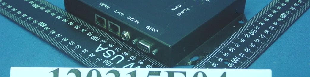
Click to zoom
Application Details
- Equipment Class
- DSS - Part 15 Spread Spectrum Transmitter
- Date of Grant
- Apr 22, 2012
- Application Purpose
- Original Equipment
- Date of Application
- Apr 22, 2012
- Equipment Note
- WNC RFID Smart Reader
- Frequency Range
- 902.75000000 - 927.25000000
- Company
- Wistron NeWeb Corporation
- Country
- Taiwan
Documents & Files
Document Text
Text extracted from the exhibit documents filed with the FCC. Open a document above to read the original.
Users Manual
RFID Smart Reader with Fan-out Box and RF Switch User Manual English Table of Contents WNC RFID Smart Reader Wistron NeWeb Corporation© 1 1. GETTING STARTED .................................................................................... 2 1.1 IN THE PACKAGE ........................................................................................ 2 1.2 INTRODUCTION .......................................................................................... 2 1.3 HARDWARE OVERVIEW- RFID SMART READER ............................................ 4 1.4 HARDWARE OVERVIEW- FAN-OUT BOX ........................................................ 5 1.5 HARDWARE OVERVIEW - RF SWITCH ........................................................... 5 1.6 CONNECTING THE CABLES .......................................................................... 6 2. CONFIGURATION SOFTWARE ................................................................... 9 2.1 ACCESS THE MANAGEMENT INTERFACE ....................................................... 9 2.2 MANAGEMENT ........................................................................................... 9 3. APPENDIX .................................................................................................. 10 3.1 SPECIFICATIONS: RFID SMART READER .................................................... 10 3.2 SPECIFICATIONS: FAN-OUT BOX ................................................................ 12 3.3 SPECIFICATIONS: RF SWITCH ................................................................... 13 3.4 PIN DEFINITION ....................................................................................... 14 1 Getting Started WNC RFID Smart Reader Wistron NeWeb Corporation© 2 1. Getting Started 1.1 In the Package RFID Smart Reader Power Cord Power Adapter Fan-out Box (optional) RF Switch (optional) Note: The Fan-out Box and RF Switch work in combination to allow more antenna connections. One RFID Smart Reader can connect to one Fan-out box and four RF switches. 1.2 Introduction The WNC RFID Smart Reader (the Reader) is suitable for a variety of UHF RFID applications. It provides high level RF performance, a user-friendly software development interface and a cost competitive reader solution. Combined with a Newave Shelf Antenna, it can provide 100% readability in zone sizes of 2’x2’x2’ to 10’x10’x10’ with appropriate reader parameters and antenna setup. You can also connect the Reader to a fan-out box and 1~4 RF switches to add additional antennas. A maximum of 16 antennas are allowed for one Reader. For multi-reader applications, such as retail applications, the Reader solution can efficiently compress data size and solve data traffic issues. 1 Getting Started WNC RFID Smart Reader Wistron NeWeb Corporation© 3 Basic application: You can connect to up to four antennas and use a computer to monitor detected parameters. Advanced application: Use the Reader with a Fan-out Box and an RF Switch to connect up to 16 antennas. 1 Getting Started WNC RFID Smart Reader Wistron NeWeb Corporation© 4 1.3 Hardware Overview- RFID Smart Reader Front Panel Rear Panel WAN Connect a standard RJ-45 Ethernet cable to the port to establish a network connection. This feature allows you to configure settings or read the data from the Reader on your computer via a Graphic User Interface. WAN port supports Power over Ethernet (PoE). LAN Currently unavailable. DC IN Connect the power adapter to the Reader via this inlet to power on the Reader. GPIO For GPIO purposes such as connecting a Fan-out Box, light sensor or other sensors. Antenna Ports For RF cable insertion. The Reader supports up to four antennas at the same time. Additional connection is also possible via an optional antenna switch. Note: RJ-45 Ethernet cable and RF cable not included in the package. 1 Getting Started WNC RFID Smart Reader Wistron NeWeb Corporation© 5 1.4 Hardware Overview- Fan-out Box OUTPUT For RF Switch connection. INPUT Connect to the GPIO port of the Reader. Device 1 & 2 Sensor data input/output ports for other applications, for example, connecting to entrance and exit sensors for security control. 1.5 Hardware Overview - RF Switch INPUT Connect to an OUTPUT port of the Fan-out Box. RF IN Connect to an antenna port of the Reader. ANT 1~4 For antenna connection. 1 Getting Started WNC RFID Smart Reader Wistron NeWeb Corporation© 6 1.6 Connecting the Cables Basic installation: 1. Plug an RF cable into an antenna port and an antenna. The Reader supports up to four antennas at the same time. 2. Connect an RJ-45 Ethernet cable to the WAN port and to your computer for software development interface configuration. 3. Connect the power adapter to the DC IN inlet on the Reader. Once the power adapter is connected to the Reader, the Power LED indicator will turn green indicating the power is on. Note: Reader may be wall-mounted. Insert screws via the four holes on the left and right side of the Reader. 1 Getting Started WNC RFID Smart Reader Wistron NeWeb Corporation© 7 Installation with Fan-out Box and RF Switch: 1 Getting Started WNC RFID Smart Reader Wistron NeWeb Corporation© 8 1. Use an RF cable to connect an antenna port of the Reader to the RF IN port of the RF Switch, and then connect the antennas to the ANT1~4 ports of the RF Switch. 2. Use a DB9 cable to connect the GPIO port of the Reader and the INPUT port of the Fan-out box. Note: Only use a rollover type DB9 cable (not crossover type.) The cable must be shorter than 5m. 3. Use a DB9 cable to connect an OUTPUT port of the Fan-out Box to the INPUT port of the RF Switch. Note: Only use a rollover type DB9 cable shorter than 30m. 4. Connect the Reader to a computer. Attach the power supply to the Reader and plug it into a wall outlet. 5. You can also connect the Device1 & 2 ports to receive data from other devices such as sensors. Note: The Reader, Fan-out Box and the RF Switch may be wall-mounted. Insert screws via the four holes on the left and right side …
Text truncated - open the document above for the full version.
Cover Letter(s)
AGENCY AUTHORIZATION LETTER Date: 2011-05-05 I, Troy Chien, am Senior Principal Engineer for Wistron NeWeb Corp. hereby authorize the following to act on our behalf, as our agent, in all matters relating to all processes required according to FCC approval for Wistron NeWeb Corp. products (Grantee Code: NKR) Brown Wang If you have any questions regarding the authorization, please don’t hesitate to contact us. Sincerely, Sincerely, ____________ _______________ Troy Chien / Senior Principal Engineer Wistron NeWeb Corp. Tel: 886-3-6667799 Ext 6361 Fax: 886-3-6667323 E-mail: [email protected]
External Photos
Report No.: 120315E04 1 CONSTRUCTION PHOTOS OF EUT Report No.: 120315E04 6 Power Adapter: AMS4-1202000F Report No.: 120315E04 7 Report No.: 120315E04 8 POE adapter: POE36U-1AT-R Report No.: 120315E04 9 Report No.: 120315E04 10 Report No.: 120315E04 11 Report No.: 120315E04 12
ID Label/Location Info
(Fig.1) FCC ID: NKRBLANKA FCC LABEL LOCATION The label will be permanently affixed at a conspicuous location on the device.
Internal Photos
Report No.: 120315E04 2 Report No.: 120315E04 3 Report No.: 120315E04 4 Report No.: 120315E04 5
RF Exposure Info
Report No.: SA120315E04 Report Format Version 4.0.0. 1 RF EXPOSURE REPORT REPORT NO.: SA120315E04 MODEL NO.: BLANKA FCC ID: NKRBLANKA RECEIVED: Mar. 15, 2012 TESTED: Apr. 13, 2012 ISSUED: Apr. 19, 2012 APPLICANT: Wistron NeWeb Corp. ADDRESS: 20 Park Avenue II, Hsinchu Science Park,Hsinchu 308, Taiwan, R.O.C. ISSUED BY : Bureau Veritas Consumer Products Services (H.K.) Ltd., Taoyuan Branch Hsin Chu Laboratory LAB ADDRESS : No. 81-1, Lu Liao Keng, 9th Ling, Wu Lung Tsuen, Chiung Lin Hsiang, Hsin Chu Hsien 307, Taiwan, R.O.C. This test report consists of 6 pages in total. It may be duplicated completely for legal use with the approval of the applicant. It should not be reproduced, except in full, without the written approval of our laboratory. The client should not use it to claim product certification, approval or endorsement by any government agency. The test results in the report only apply to the tested sample. Report No.: SA120315E04 Report Format Version 4.0.0. 2 TABLE OF CONTENTS RELEASE CONTROL RECORD....................................................................................3 1. CERTIFICATION.....................................................................................................4 2. RF EXPOSURE LIMIT.............................................................................................5 3. MPE CALCULATION FORMULA............................................................................5 4. CLASSIFICATION...................................................................................................5 5. ANTENNA GAIN......................................................................................................5 6. CALCULATION RESULT OF MAXIMUM CONDUCTED POWER..........................6 Report No.: SA120315E04 Report Format Version 4.0.0. 3 RELEASE CONTROL RECORD ISSUE NO. REASON FOR CHANGE DATE ISSUED SA120315E04 Original release Apr. 19, 2012 Report No.: SA120315E04 Report Format Version 4.0.0. 4 1.CERTIFICATION PRODUCT: WNC RFID Smart Reader BRAND NAME: WNC MODEL NO.: BLANKA TEST SAMPLE: ENGINEERING SAMPLE APPLICANT: Wistron NeWeb Corp. TESTED: Dec. 06, 2011 STANDARDS: FCC Part 2 (Section 2.1091) FCC OET Bulletin 65, Supplement C (01-01) IEEE C95.1 The above equipment (Model: BLANKA) has been tested by Bureau Veritas Consumer Products Services (H.K.) Ltd., Taoyuan Branch, and found compliance with the requirement of the above standards. The test record, data evaluation & Equipment Under Test (EUT) configurations represented herein are true and accurate accounts of the measurements of the sample’s EMC characteristics under the conditions specified in this report. PREPARED BY : , DATE: Apr. 19, 2012 ( Claire Kuan, Specialist) APPROVED BY : , DATE: Apr. 19, 2012 ( May Chen, Deputy Manager ) Report No.: SA120315E04 Report Format Version 4.0.0. 5 2. RF EXPOSURE LIMIT LIMITS FOR MAXIMUM PERMISSIBLE EXPOSURE (MPE) FREQUENCY RANGE (MHz) ELECTRIC FIELD STRENGTH (V/m) MAGNETIC FIELD STRENGTH (A/m) POWER DENSITY (mW/cm 2 ) AVERAGE TIME (minutes) LIMITS FOR GENERAL POPULATION / UNCONTROLLED EXPOSURE 300-1500 ... ... F/1500 30 1500-100,000 ... ... 1.0 30 F = Frequency in MHz 3. MPE CALCULATION FORMULA Pd = (Pout*G) / (4*pi*r 2 ) where Pd = power density in mW/cm 2 Pout = output power to antenna in mW G = gain of antenna in linear scale pi = 3.1416 r = distance between observation point and center of the radiator in cm 4. CLASSIFICATION The antenna of this product, under normal use condition, is at least 20cm away from the body of the user. So, this device is classified as Mobile Device. 5.Antenna Gain The antenna provided to the EUT, please refer to the following table: Brand Model Antenna Type Gain (dBi) Cable Loss(dB) Net Gain (dBi) Antenna Connector Cable Length WNC XRAB-N1 Shelf Antenna 5 1 4 RTNC 150cm Report No.: SA120315E04 Report Format Version 4.0.0. 6 6.CALCULATION RESULT OF MAXIMUM CONDUCTED POWER FREQUENCY BAND (MHz) MAX POWER (mW) ANTENNA GAIN (dBi) DISTANCE (cm) POWER DENSITY (mW/ cm 2 ) LIMIT (mW/cm 2 ) 902.75 ~ 927.25 691.831 4 20 0.346 0.6 Note: Limit of Power Density = F/1500 --- END --- Directional gain = gain of antenna element + 10 log (# of TX antenna elements) Effective Legacy Gain (dBi)=6.5 CONCLUSION: Both of the WLAN and Bluetooth can transmit simultaneously, the formula of calculated the MPE is: CPD 1 / LPD 1 + CPD 2 / LPD 2 + ......etc. < 1 CPD = Calculation power density LPD = Limit of power density Therefore, the worst-case situation is 0.085 / 1 + 0.006 / 1 = 0.091, which is less than “1”. This confirmed that the device comply with FCC 1.1310 MPE limit.
Test Report
Report No.: RF120315E04 1 Report Format Version 4.2.0 Reference No.: 110819E02 FCC TEST REPORT REPORT NO.: RF120315E04 MODEL NO.: BLANKA FCC ID: NKRBLANKA RECEIVED: Mar. 15, 2012 TESTED: Mar. 19 to Apr. 13, 2012 TESTEFFD: Apr. 19, 2012 APPLICANT: Wistron NeWeb Corp. ADDRESS: 20 Park Avenue II, Hsinchu Science Park,Hsinchu 308, Taiwan, R.O.C. ISSUED BY : Bureau Veritas Consumer Products Services (H.K.) Ltd., Taoyuan Branch Hsin Chu Laboratory LAB ADDRESS : No. 81-1, Lu Liao Keng, 9th Ling, Wu Lung Tsuen, Chiung Lin Hsiang, Hsin Chu Hsien 307, Taiwan, R.O.C. TEST LOCATION (1): No. 81-1, Lu Liao Keng, 9th Ling, Wu Lung Tsuen, Chiung Lin Hsiang, Hsin Chu Hsien 307, Taiwan, R.O.C. TEST LOCATION (2): No. 49, Ln. 206, Wende Rd., Shangshan Tsuen, Chiung Lin Hsiang, Hsin Chu Hsien 307, Taiwan, R.O.C. This test report consists of 58 pages in total. It may be duplicated completely for legal use with the approval of the applicant. It should not be reproduced except in full, without the written approval of our laboratory. The client should not use it to claim product endorsement by TAF or any government agencies. The test results in the report only apply to the tested sample. Report No.: RF120315E04 2 Report Format Version 4.2.0 Reference No.: 110819E02 TABLE OF CONTENTS RELEASE CONTROL RECORD............................................................................................4 1 CERTIFICATION.....................................................................................................5 2 SUMMARY OF TEST RESULTS..............................................................................6 2.1 MEASUREMENT UNCERTAINTY...........................................................................7 3 GENERAL INFORMATION......................................................................................8 3.1 GENERAL DESCRIPTION OF EUT........................................................................8 3.2 DESCRIPTION OF TEST MODES........................................................................10 3.3 TEST MODE APPLICABLITY AND TESTED CHANNEL DETAIL:.........................11 3.4 GENERAL DESCRIPTION OF APPLIED STANDARDS........................................13 3.5 DESCRIPTION OF SUPPORT UNITS...................................................................14 3.6 CONFIGURATION OF SYSTEM UNDER TEST....................................................15 4 TEST PROCEDURES AND RESULTS..................................................................17 4.1 CONDUCTED EMISSION MEASUREMENT.........................................................17 4.1.1 LIMITS OF CONDUCTED EMISSION MEASUREMENT.......................................17 4.1.2 TEST INSTRUMENTS...........................................................................................17 4.1.3 TEST PROCEDURES...........................................................................................18 4.1.4 DEVIATION FROM TEST STANDARD..................................................................18 4.1.5 TEST SETUP........................................................................................................19 4.1.6 EUT OPERATING CONDITIONS...........................................................................19 4.1.7 TEST RESULTS(POE MODE)...............................................................................20 4.1.8 TEST RESULTS(ADAPTER MODE)......................................................................22 4.2 NUMBER OF HOPPING FREQUENCY USED......................................................24 4.2.1 LIMIT OF HOPPING FREQUENCY USED............................................................24 4.2.2 TEST INSTRUMENTS...........................................................................................24 4.2.3 TEST PROCEDURES...........................................................................................25 4.2.4 DEVIATION FROM TEST STANDARD..................................................................25 4.2.5 TEST SETUP........................................................................................................26 4.2.6 TEST RESULTS....................................................................................................26 4.3 DWELL TIME ON EACH CHANNEL......................................................................28 4.3.1 LIMIT OF DWELL TIME USED..............................................................................28 4.3.2 TEST INSTRUMENTS...........................................................................................28 4.3.3 TEST PROCEDURES...........................................................................................29 4.3.4 DEVIATION FROM TEST STANDARD..................................................................29 4.3.5 TEST SETUP........................................................................................................29 4.3.6 TEST RESULTS....................................................................................................30 4.4 CHANNEL BANDWIDTH.......................................................................................32 4.4.1 TEST INSTRUMENTS...........................................................................................32 4.4.2 TEST PROCEDURE..............................................................................................33 4.4.3 DEVIATION FROM TEST STANDARD..................................................................33 4.4.4 TEST SETUP........................................................................................................33 4.4.5 EUT OPERATING CONDITION.............................................................................33 4.4.6 TEST RESULTS....................................................................................................34 Report No.: RF120315E04 3 Report Format Version 4.2.0 Reference No.: 110819E02 4.5 HOPPING CHANNEL SEPARATION..................................................................…
Text truncated - open the document above for the full version.
Test Setup Photos
Report No.: 120315E04 1 PHOTOGRAPHS OF THE TEST CONFIGURATION CONDUCTED EMISSION TEST (POE) Report No.: 120315E04 2 CONDUCTED EMISSION TEST (Adapter) Report No.: 120315E04 3 RADIATED EMISSION TEST Report No.: 120315E04 4
Contact Information
Applicant
William Su(Senior Director / System Engineering dept.)
Technical Contact
Bureau Veritas CPS (H.K.) Ltd. Taoyuan BranchHank Chung
[email protected]886-3-593-5343
81-1, Lu Laio Keng, 9th Ling, Wu Lung Tsuen, Chiun · Hsinchu Hsien · Taiwan
Non-Technical Contact
Bureau Veritas CPS (H.K.) Ltd. Taoyuan BranchNatacha Chen
[email protected]886-3-3183232
Test Firm
Bureau Veritas CPS (H.K.) Ltd. Taoyuan BranchRichard Chen
Technical Specifications
| # | Rule Parts | Frequency Range | Power Output |
|---|---|---|---|
| 1 | 15C | 902.75 MHz - 927.25 MHz | 692.00 mW |
Other Applications from Wistron NeWeb Corporation
NKR-ATTCGW453
Aug 25, 2026Enterprise product
Equipment Class
NII - Unlicensed National Information Infrastructure TXNKR-LS06B
Aug 24, 2026Touchscreen
Equipment Class
NII - Unlicensed National Information Infrastructure TXNKR-DWSZW
Aug 10, 2026Door/Window Sensor
Equipment Class
DXX - Part 15 Low Power Communication Device TransmitterNKR-TELE2
Jun 26, 2026TELE2
Equipment Class
NII - Unlicensed National Information Infrastructure TXNKR-VMC-SA525MAX
Jun 05, 2026NAD (Network Access Device)
Equipment Class
CXX - Communications Rcvr for use w/ licensed Tx and CBs