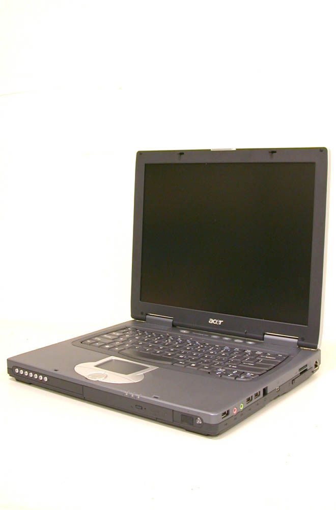
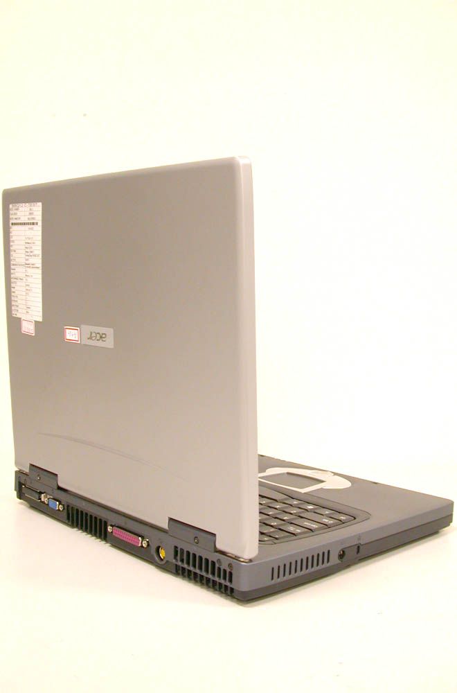
NKRBQ12BTravelMate 430 Series Notebook w/ 802.11b LAN
Wistron NeWeb Corporation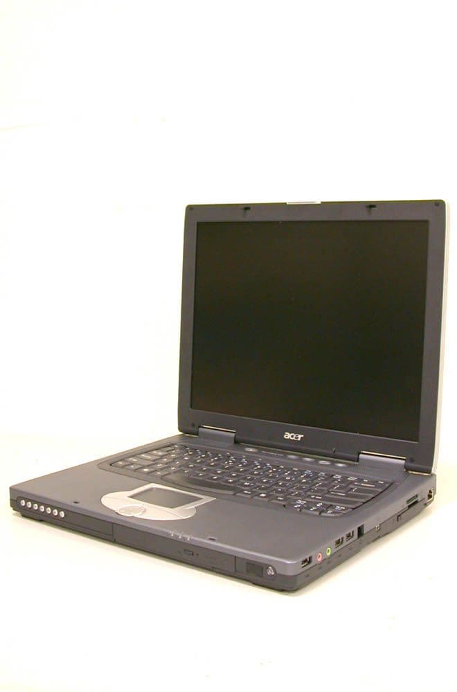
Click to zoom
Application Details
- Equipment Class
- DTS - Digital Transmission System
- Date of Grant
- Mar 04, 2003
- Application Purpose
- Original Equipment
- Date of Application
- Mar 04, 2003
- Equipment Note
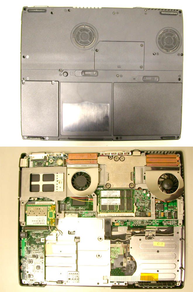
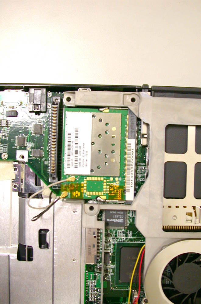
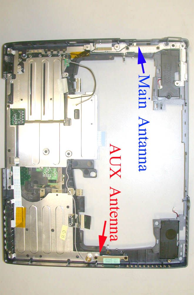
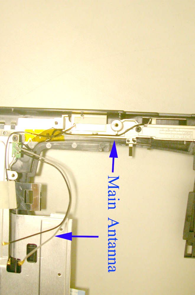
- TravelMate 430 Series Notebook w/ 802.11b LAN
- Frequency Range
- 2412.00000000 - 2462.00000000
- Company
- Wistron NeWeb Corporation
- Country
- Taiwan
Documents & Files
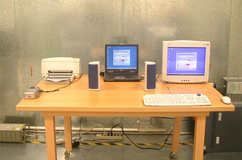
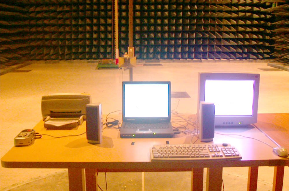
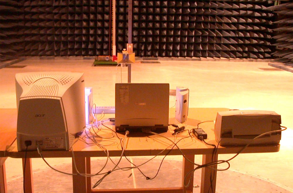
Document Text
Text extracted from the exhibit documents filed with the FCC. Open a document above to read the original.
Users Manual
TravelMate 430 Series User’s Guide Model BQ12 Changes may be made periodically to the information in this publication without obligation to notify any person of such revision or changes. Such changes will be incorporated in new editions of this manual or supplementary documents and publications. This company makes no representations or warranties, either expressed or implied, with respect to the contents hereof and specifically disclaims the implied warranties of merchantability or fitness for a particular purpose. Record the model number, serial number, purchase date, and place of purchase information in the space provided below. The serial number and model number are recorded on the label affixed to your computer. All correspondence concerning your unit should include the serial number, model number, and purchase information. No part of this publication may be reproduced, stored in a retrieval system, or transmitted, in any form or by any means, electronic, mechanical, photocopy, recording, or otherwise, without the prior written permission of Acer Incorporated. Model number : _________________________________ Serial number: ___________________________________ Purchase date: ___________________________________ Place of purchase: ________________________________ Copyright © 2003 Acer Incorporated. All Rights Reserved. TravelMate 430 Series Notebook Computer User's Guide Original Issue: January 2003 TravelMate 430 series Notebook computer Acer and the Acer logo are registered trademarks of Acer Incorporated. Other company's product names or trademarks are used herein for identification purposes only and belong to their respective companies. 1 Federal Communication Commission Interference Statement This equipment has been tested and found to comply with the limits for a Class B digital device, pursuant to Part 15 of the FCC Rules. These limits are designed to provide reasonable protection against harmful interference in a residential installation. This equipment generates, uses and can radiate radio frequency energy and, if not installed and used in accordance with the instructions, may cause harmful interference to radio communications. However, there is no guarantee that interference will not occur in a particular installation. If this equipment does cause harmful interference to radio or television reception, which can be determined by turning the equipment off and on, the user is encouraged to try to correct the interference by one of the following measures: - Reorient or relocate the receiving antenna. - Increase the separation between the equipment and receiver. - Connect the equipment into an outlet on a circuit different from that to which the receiver is connected. - Consult the dealer or an experienced radio/TV technician for help. FCC Caution: To assure continued compliance, (example - use only shielded interface cables when connecting to computer or peripheral devices) any changes or modifications not expressly approved by the party responsible for compliance could void the user's authority to operate this equipment. This device complies with Part 15 of the FCC Rules. Operation is subject to the following two conditions: (1) This device may not cause harmful interference, and (2) This device must accept any interference received, including interference that may cause undesired operation. IMPORTANT NOTE: FCC Radiation Exposure Statement: This equipment complies with FCC radiation exposure limits set forth for an uncontrolled environment. This transmitter must not be co-located or operating in conjunction with any other antenna or transmitter. iii English First things first We would like to thank you for making the TravelMate series of notebook computers your choice for your mobile computing needs. We hope you will be happy with your TravelMate as much as we enjoyed making it for you. Your guides To help you use your TravelMate, we have designed a set of guides: For more information about our products, services, and support information, please visit our Web site (global.acer.com). First off, the Just for Starters... poster helps you get started with setting up your computer. This User’s Guide introduces you to the many ways your computer can help you be more productive. This guide provides clear and concise information about the computer, so read it thoroughly. If you ever need to print out a copy, this User’s guide is also available in PDF (Portable Document Format). Follow these steps: 1 Click on Start, Programs, AcerSystem. 2 Click on AcerSystem User’s Guide. Note: Viewing the file requires Adobe Acrobat Reader installed. For instructions on how to use Adobe Acrobat Reader, access the Help menu. iv English Basic care and tips for using your computer Turning your computer on and off To turn on the computer, simply press the power button - the leftmost button above the keybaord of your TravelMate. See page 3 for the exact location of the power button. To turn the power off, do any of the following: •Use the Windows shutdown command For Windows 2000: Click on Start, Shut Down..., and select Shut down; then click on OK. - or - For Windows XP: Click on Start, Tur n off Computer; then click Turn Off. •Use the power switch Note: You can also use the power switch to perform power management functions. See Windows help for more information. •Use the customized functions for power management You can also shut down the computer by closing the display cover, or by pressing the sleep hot key (Fn-F4). See “Hot keys” on page 15. Note: If you cannot power off the computer normally, press and hold the power switch for more than four seconds to shut down the computer. If you turn off the computer and want to turn it on again, wait at least two seconds before powering up. Taking care of your computer Your computer will serve you well if you take care of it. •Do not expose the computer to direct sunlight. Do not place it near sources of heat, such as a radiator. •Do not expose the computer to te…
Text truncated - open the document above for the full version.
Users Manual
1 Getting to know your TravelMate 32 English Securing your computer Your computer is a valuable investment that you need to take care of. Learn how to protect and take care of your computer. Security features include hardware and software locks — a security notch and passwords. Using a computer security lock A security keylock notch located on the left panel of the computer lets you connect a Kensington-compatible computer security lock. Wrap a computer security lock cable around an immovable object such as a table or locked drawer handle. Insert the lock into the notch and turn the key to secure the lock. Some keyless locks are also available. Using passwords Passwords protect your computer from unauthorized access. Setting these passwords creates several different levels of protection for your computer and data: •Supervisor Password prevents unauthorized entry into the BIOS Utility. Once set, you must key-in this password to gain access to the BIOS Utility. See “BIOS Utility” on page 44 for more details. •User Password secures your computer against unauthorized use. Combine the use of this password with password checkpoints on boot-up and resume from hibernation for maximum security. •Password on Boot secures your computer against unauthorized use. Combine the use of this password with password checkpoints 33 English on boot-up and resume from hibernation for maximum security. •Hard Disk Password protects your data by preventing unauthorized access to your hard disk. Even if the hard disk is removed from the computer and moved to another computer, it cannot be accessed without the Hard Disk Password. Important! Do not forget your Supervisor and Hard Disk Password! If you forget your password, please get in touch with your dealer or an authorized service center. Entering passwords When a password is set, a password prompt appears in the left-hand corner of the display screen. •When the Supervisor Password is set, a prompt appears when you press F2 to enter the BIOS Utility at boot-up. •Type the Supervisor Password and press Enter to access the BIOS Utility. If you enter the password incorrectly, a warning message appears. Try again and press Enter. •When the User Password is set and the Password on boot parameter is enabled, a prompt appears at boot-up. •Type the User Password and press Enter to use the computer. If you enter the password incorrectly, a warning message appears. Try again and press Enter. •When the Hard Disk Password is set, a prompt appears at boot-up. •Type the Hard Disk Password and press Enter to use the computer. If you enter the password incorrectly, a warning message appears. Try again and press Enter. Important! You have three chances to enter a password. If you fail to enter the password correctly after three tries, the system halts. Press the power button for four seconds to shut down the computer. Then turn on the computer again, and try again. If you fail to enter the Hard Disk Password, please contact your dealer or an authorized service center. Setting passwords You can set passwords using the BIOS Utility. 1 Getting to know your TravelMate 34 English 2 Customizing my computer After learning the basics of your TravelMate computer, let’s get acquainted with the advanced features of your computer. In this chapter, you will learn how to add options, upgrade components for better performance, and customize your computer. 37 English Expanding through options Your TravelMate offers you a complete mobile computing experience. Connectivity options Ports allow you to connect peripheral devices to your computer as you would with a desktop PC. Fax/data modem Your computer have a built-in V.90/92 56Kbps AC’97 Link fax/data modem. Warning! This modem port is not compatible with digital phone lines. Plugging this modem into a digital phone line will damage the modem. To use the fax/data modem port, connect a phone cable from the modem port to a telephone jack. Start your communications software program. 2 Customizing my computer 38 English Built-in network feature The built-in network feature allows you to connect your computer to an Ethernet-based (10/100 Mbps) network. To use the network feature, connect an Ethernet cable from the network jack on the right side of the computer to a network jack or hub on your network. Universal Serial Bus The Universal Serial Bus (USB) port is a high-speed serial bus which allows you to connect and daisy-chain USB peripherals without taking 39 English up precious system resources. Your computer has three USB 2.0 ports available. IEEE 1394 port The computer's IEEE 1394 port allows you to connect to an IEEE 1394 supported devices like a video camera or digital camera. See your video or digital camera's documentation for details. PC Card slot The type II CardBus PC Card slot found on the right side of the computer accepts credit-card-sized cards that enhance the usability and expandability of the computer. These cards should have a PC Card logo on them. 2 Customizing my computer 40 English PC Cards (formerly PCMCIA) are add-on cards for portable computers, giving you expansion possibilities long afforded by desktop PCs. Popular PC cards include fax/data modem, LAN, wireless LAN and SCSI cards. CardBus improves on the 16-bit PC card technology by expanding the bandwidth to 32 bits. Note: Refer to your card’s manual for details on how to install and use the card and its functions. Inserting a PC Card Insert the card into the slot and make the proper connection (e.g., network cable), if necessary. See your card manual for details. Ejecting a PC Card Before ejecting a PC Card: 1Exit the application using the card. 2Left-click on the PC Card icon on the taskbar and stop the card operation. 41 English 3Press the slot eject button to pop out the eject button (a); then press it again to eject the card (b). Upgrade options Your computer delivers superior power and performance. However, some users and the applications they use may demand more. This…
Text truncated - open the document above for the full version.
Users Manual
IEEE 802.11b Mini PCI Module EM9-NB Users Guide 1 Federal Communication Commission Interference Statement This equipment has been tested and found to comply with the limits for a Class B digital device, pursuant to Part 15 of the FCC Rules. These limits are designed to provide reasonable protection against harmful interference in a residential installation. This equipment generates, uses and can radiate radio frequency energy and, if not installed and used in accordance with the instructions, may cause harmful interference to radio communications. However, there is no guarantee that interference will not occur in a particular installation. If this equipment does cause harmful interference to radio or television reception, which can be determined by turning the equipment off and on, the user is encouraged to try to correct the interference by one of the following measures: - Reorient or relocate the receiving antenna. - Increase the separation between the equipment and receiver. - Connect the equipment into an outlet on a circuit different from that to which the receiver is connected. - Consult the dealer or an experienced radio/TV technician for help. FCC Caution: To assure continued compliance, (example - use only shielded interface cables when connecting to computer or peripheral devices) any changes or modifications not expressly approved by the party responsible for compliance could void the user's authority to operate this equipment. This device complies with Part 15 of the FCC Rules. Operation is subject to the following two conditions: (1) This device may not cause harmful interference, and (2) This device must accept any interference received, including interference that may cause undesired operation. IMPORTANT NOTE: FCC Radiation Exposure Statement: This equipment complies with FCC radiation exposure limits set forth for an uncontrolled environment. This transmitter must not be co-located or operating in conjunction with any other antenna or transmitter. 2 Table of Contents Regulatory Information......................................................! Table of Contents...........................................................................................................2 1. Quick Software Installation Guide...............................................................................3 2. Step-by-Step Software Installation Guide...................................................................6 2.1 INSTALLATION UNDER WINDOWS XP...............................................................................................................6 2.2 INSTALLATION UNDER WINDOWS 98SE/2000/ME...........................................................................................7 3. Software Uninstallation Guide....................................................................................9 3.1 UNINSTALLATION UNDER WINDOWS XP..........................................................................................................9 3.2 UNINSTALLATION UNDER WINDOWS 98SE/2000/ME....................................................................................11 4. Configuration............................................................................................................12 4.1 CONFIGURATION UNDER WINDOWS XP.........................................................................................................12 4.2 CONFIGURATION UNDER WINDOWS 98SE/2000/ME......................................................................................16 5. Using IEEE802.11b WLAN Utility...............................................................................20 5.1 LAN STATUS.................................................................................................................................................20 5.2 LINK INFORMATION........................................................................................................................................21 5.3 SITE SURVEY..................................................................................................................................................21 5.4 DIAGNOSTIC...................................................................................................................................................22 5.5 ABOUT...........................................................................................................................................................22 6. Networking Applications...........................................................................................23 6.1 SURVEYING THE NETWORK NEIGHBORHOOD..................................................................................................23 6.2 FILE SHARING................................................................................................................................................24 6.3 USING THE SHARED FOLDER...........................................................................................................................25 3 1. Quick Software Installation Guide If you are familiar with computer networking, this Quick Start Guide is the fastest way for you to establish your wireless network. If you need more information than this Quick Start Guide can provide, the following chapters will guide you through the necessary steps. The quick installation guide is based on Windows XP. 1. Insert the installation software CD into the computer. 2. Follow the displayed instructions to complete installation. 3. WLAN icon displays on the desktop after the installation. 4 4. Click Start>Settings>Network Connections, and double click the Wireless Network Connection of “802.11b Wireless LAN PCI Card”. From the available networks list, choose one network and enter the network key (if necessary). Click “Connect”. 5. From Windows System Tray, a dialog box pops up which shows you the Network name and the Signal Strength. 6. Double click on “Wireless Network Connection” icon from the Windows …
Text truncated - open the document above for the full version.
Block Diagram
EM9-NB Hardware Block Diagram 2.4G Hz ~2.5G Hz 374M Hz Digital Channel frequency(2412~2484)-374 M Hz 748M Hz
Cover Letter(s)
No. 120, Lane 180, San Ho Tsuen, Hsin Ho Rd. Lung-Tan Hsiang, Tao Yuan County 325 Taiwan, R.O.C. Daphne Liu Page 1 of 2 Dear Bill, Here are our answers: 1.) Please refer to your Restricted Band radiated measurements at 2483.5MHz. The FCC average limit is 500 microvolts (57dBuV) at 3 meters. Your data shows 59.67dBuV, or 926 microvolts. Please review. ANS: The 59.67dBuV listed in Spectrum Reading Column of Page29 is the raw data from spectrum analyzer. The emission of 2483.5MHz is 46.19 dBuV/m listed in Emission Level Column. The relation between Spectrum Reading and Emission Level is listed below: Emission level= Spectrum reading + Correction Factor Correction Factor = Cable loss + Ant.factor – amp.Gain = -13.48dB @ 2483.5MHz. We are so sorry for not clearly listing the corrected factor and formular in test report The updated test report has corrected this error. 2.) The plots presented for the band edge radiated measurements are very difficult to read and interpret. In the future, please supply larger and clearer plots. ANS:We will improve it in the next report. Thanks. 3.) The Spectral Power Density test should be made over a span of at minimum 1.5MHz. Please supply corrected plot using the time constants as specified in 15.247. ANS:The retest power density data is updated in the revised test report. 4.) The radiated test procedure for measurements above 1GHz is in error. Measurements should always be made with a 1MHz RBW and a 1MHz VBW, especially on harmonic measurements. If failures occur, an additional averaging measurement using a 1MHz RBW with as little as a 10Hz VBW is permitted. This average reading is then compared to the limit ANS:Yes ,we have an error for mixing the FCC and Europe Standard in test procedure statement above 1GHz, but in really test, the RBW and VBW, we follow the para 6.3 table in Page 16 of test report. So, the data we testing is correct. The test procedure of radiated measurement above 1GHz has been revised. Please refer to the revised test report. (to be continued) Page 1 of 2 5.) It is not clear how high in the frequency domain harmonic measurements were made. Please provide corrected measurement procedure and test data. Measurements according to FCC rules are required to the 10 th harmonic. ANS:We also updated the test procedure statement for harmonic frequrenise please refer to page 16 of test report. And the test data for frequencies up to 10 th harmonic was also listed in the revised test report. Please review the answers Thanks for your help. Best Regards, Daphne Liu
Cover Letter(s)
American Telecommunications Certification Body Inc. 6731 Whittier Ave, McLean, VA 22101 February 19, 2003 RE: Winston Ne Web FCC ID: NKRBQ12B I have a couple of comments on this Application. 1.) Please refer to your Restricted Band radiated measurements at 2483.5MHz. The FCC average limit is 500 microvolts (57dBuV) at 3 meters. Your data shows 59.67dBuV, or 926 microvolts. Please review. 2.) The plots presented for the band edge radiated measurements are very difficult to read and interpret. In the future, please supply larger and clearer plots. 3.) The Spectral Power Density test should be made over a span of at minimum 1.5MHz. Please supply corrected plot using the time constants as specified in 15.247. 4.) The radiated test procedure for measurements above 1GHz is in error. Measurements should always be made with a 1MHz RBW and a 1MHz VBW, especially on harmonic measurements. If failures occur, an additional averaging measurement using a 1MHz RBW with as little as a 10Hz VBW is permitted. This average reading is then compared to the limit 5.) It is not clear how high in the frequency domain harmonic measurements were made. Please provide corrected measurement procedure and test data. Measurements according to FCC rules are required to the 10 th harmonic. William H. Graff President and Examining Engineer mailto: [email protected] The items indicated above must be submitted before processing can continue on the above referenced application. Failure to provide the requested information may result in application termination. Correspondence should be considered part of the permanent submission and may be viewed from the Internet after a Grant of Equipment Authorization is issued. Please do not respond to this correspondence using the email reply button. In order for your response to be processed expeditiously, you must submit your documents through the AmericanTCB.com website. Also, please note that partial responses increase processing time and should not be submitted. Any questions about the content of this correspondence should be directed to the sender.
Cover Letter(s)
Rev 2 E:\Ready_To_Convert\Doc\307595.DOC 02/08/02 American Telecommunications Certification Body, Inc. 6731 Whittier Avenue McLean, VA 22101 Ph: (703) 847-4700 FAX: (703) 847-6888 Certification Application Package AmericanTCB CERTIFICATION APPLICATION Rev 2 E:\Ready_To_Convert\Doc\307595.DOC 02/08/02 Wistron NeWeb Corporation No. 10-1, Li-hsin Road I, Science-based Inductrial Park Hsinchu 300, Taiwan, R. O. C. This TESTING AND CERTIFICATION AGREEMENT ("Agreement") is made effective as of the latter date of execution below, by and between American Telecommunication Certification Body (ATCB) and Wistron NeWeb Corporation (Applicant), collectively referred to as "the Parties". Equipment Description Equipment Description: Notebook Personal Computer Model Number: BQ12 FCC Rule Part(s): 15C In consideration of the mutual covenants in this Agreement, ATCB or its subcontractors will perform certification inspection services to determine if Applicant's device(s) identified above under Equipment Description (hereinafter "Devices") are in compliance with the laws, regulations and technical standards (hereinafter "Certification Regulations") of the national authorities specified by Applicant in Schedule A. 1. General 1.1 This Agreement is for the purpose of testing and certification and applies to all tests, audits, and certifications for the Devices, and will be performed in accordance with the Certification Regulations of the national authorities specified in Schedule A. 1.2 ATCB retains full discretion to determine if the Devices are compliant with the Certification Regulations of the Countries. In the event that certification is not issued for the aforementioned Devices, ATCB agrees to advise Applicant in writing of the reasons thereof. 1.3 This Agreement may not be assigned to or acquired by any other person, firm, or corporation without ATCB's written authorization. 2. Scope of Performance 2.1 The scope of performance between the Parties shall be agreed to by contract, purchase order or other mutually agreed-upon schedule or order. 2.2 Except as provided in Section 2.3 hereof, testing of all Devices shall take place at ATCB facilities. 2.3 In lieu of section 2.2 above, ATCB may agree to accept test data from any ISO/IEC Guide 25 accredited laboratory or FCC-Listed Laboratory and evaluate the Devices on the basis of this data. ATCB may also choose to accept test data from ISO Guide 25 accredited laboratories owned by Applicant, provided the requirements of 2.3.1. are met. 2.3.1 Employees of Applicant shall not participate in any tests, evaluations, or assessments described in sections 2.2 or 2.3 above without the presence and supervision of an ATCB engineer or technician. 2.4 If requested for sample purposes (as required by the FCC), client shall supply ATCB, at no charge, with at least one test sample of each Device, including the necessary peripherals, connecting cables, accessories or other hardware or software (hereinafter collectively referred to as "support equipment") required for testing, evaluation, and assessment. 2.5 Applicant shall supply ATCB, at no charge, with all technical documentation and materials required for the testing, evaluation, and assessment of such Devices and support equipment. 2.5.1 Technical documentation and materials include, but are not limited to, any relevant operating instructions, schematics, block diagrams, photographs, prior tests and certificates concerning the safety of the Devices, its components or support equipment. 2.6 Applicant recognizes that Device samples, including support equipment, may be damaged or completely destroyed when subjected to ATCB's testing and evaluation process. Applicant shall hold ATCB harmless for any such damage or destruction to its equipment. 2.7 If necessary ATCB shall test, evaluate, or assess Applicant's equipment within 30 business days of ATCB's receipt of such Devices, support equipment and technical documentation, and to work diligently until certification is granted or denied, or Applicant decides to abandon testing, evaluation, and assessment on such Devices. AmericanTCB CERTIFICATION APPLICATION Rev 2 E:\Ready_To_Convert\Doc\307595.DOC 02/08/02 2.8 Upon completion of testing, evaluation, or assessment, ATCB shall advise Applicant via an abbreviated report whether the results are favorable, and what, if any, conditions, limitations or qualifications to the requested Certification exist. 2.9 Applicant agrees that a full report is available to Applicant only by special request, and for the separate charge specified. 2.10 Where testing, evaluation, and assessment results in certification, ATCB shall certify Applicant's equipment as compliant with the laws, regulations and/or standards of the Countries within 30 business days from the date testing, evaluation, and assessment is completed. 2.10.1 Section 2.11 may be dependent upon a timely response by the United States Federal Communications Commission (FCC) or its foreign equivalent. 2.10.2 In the event of product certification, Applicant may request that ATCB return or destroy Applicant's Device sample(s), equipment support, and technical documentation. Applicant shall bear all costs associated with the return or destruction of such equipment test sample(s) and support equipment. 2.11 Where testing, evaluation, and assessment does not result in certification, ATCB shall provide cost-free storage for each Device sample, support equipment, and technical documentation for a period not to exceed 30 days, provided Applicant agrees to re-testing within this period when notified of the Device's failure. 2.12 If Applicant does not collect or accept receipt of the Device sample(s), support equipment and technical documentation, despite ATCB having sent notice pursuant to subsection 2.12.1, ATCB reserves the right to dispose of them at Applicant's expense. 2.13 Applicant shall retain all documents forwarded to it by ATCB as required by the Certification Regulations of the Coun…
Text truncated - open the document above for the full version.
Cover Letter(s)
Wistron Neweb Corporation No. 10-1, Li-hsin Road 1, Science-based Industrial Park,Hsinchu 300, Taiwan, R. O. C. 886-3-666-7799 886-3-666-1654 Rev 2 C:\tmp\BQ12\fcc\AP FORM.doc 02/08/02 Request for Confidentiality Date: Feb. 14, 2003 American Telecommunications Certification Body, Inc. 6731 Whittier Avenue Suite C110 McLean, VA 22101 RE: Certification Application FCC ID: NKRBQ12B Please be advised that the following information is to be held confidential on behalf of Wistron NeWeb Corporation : q Block Diagram q Schematics The application contains technical information which Wistron NeWeb Corporation deems to be trade secrets and proprietary. If made public, the information might be used to the disadvantage of the applicant in the market place. Thank you for your attention to this matter. Sincerely, ________________ Eric Liu / Sr. Manager Engineer Wistron NeWeb Corporation
ID Label/Location Info
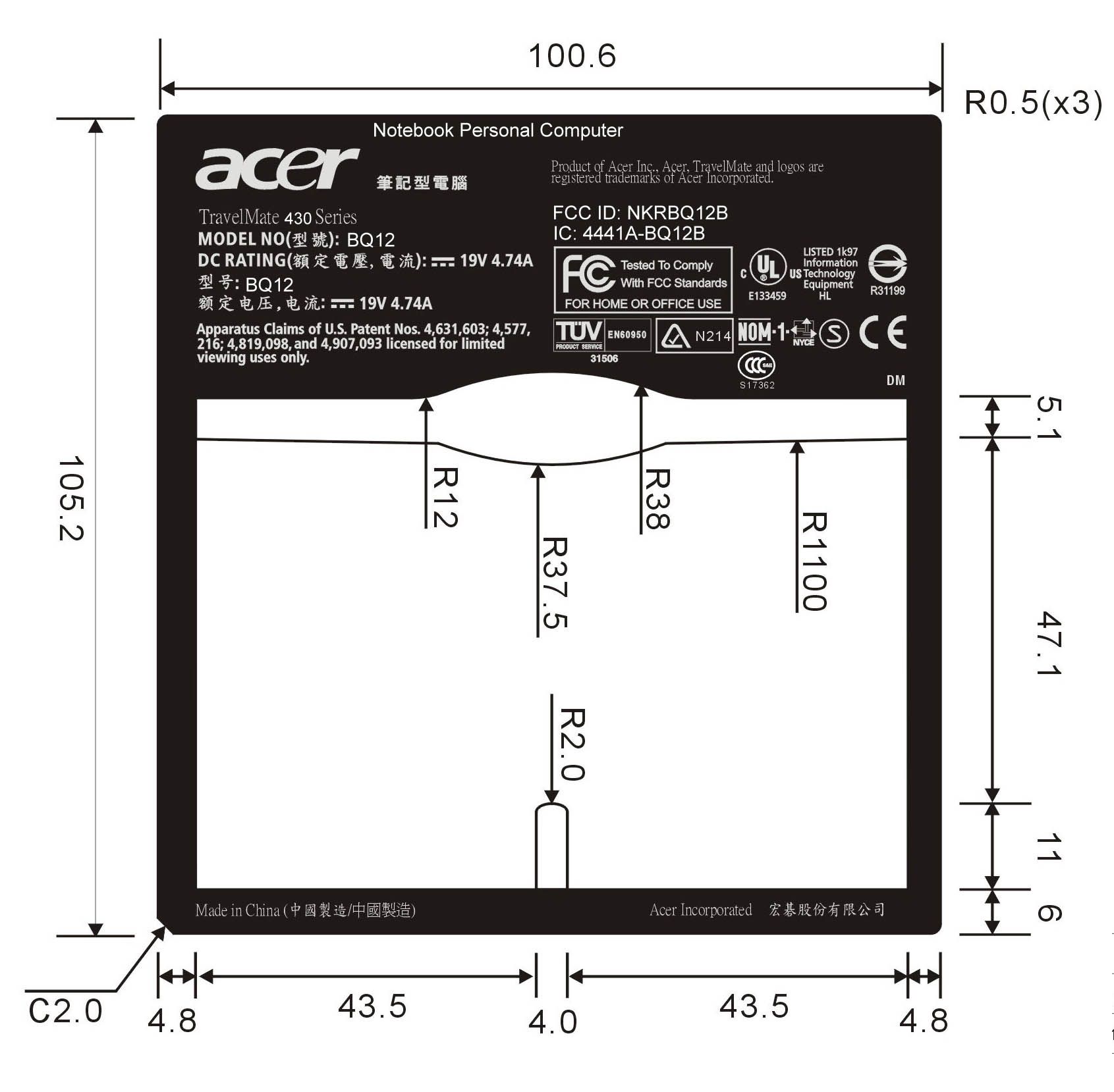
FCC Label Label Location Label Location
Operational Description
Applicant: Wistron NeWeb Corporation Manufacturer: Wistron NeWeb Corporation Product Name WLAN IEEE802.11b MiniPCI Brand Name Wistron NeWeb Model Name EM9-NB Country to be certified: None Items Contents 1. Modulation type DSSS 2. Procedure to modulation off Use PTU to transmit signal in single carrier mode 3. Number of ch…
Text truncated - open the document above for the full version.
Contact Information
Applicant
William Su(Senior Director / System Engineering dept.)
Technical Contact
International Standards LaboratoryJames Cheng
[email protected]+886 3 407 1718
No. 65, Ku Dai Keng Street · Hsichih · Taiwan
Test Firm
International Standards LaboratoryDavid Wu
Technical Specifications
| # | Rule Parts | Frequency Range | Power Output |
|---|---|---|---|
| 1 | 15C | 2.41 GHz - 2.46 GHz | 50.70 mW |
Other Applications from Wistron NeWeb Corporation
NKR-ATTCGW453
Aug 25, 2026Enterprise product
Equipment Class
NII - Unlicensed National Information Infrastructure TXNKR-LS06B
Aug 24, 2026Touchscreen
Equipment Class
NII - Unlicensed National Information Infrastructure TXNKR-DWSZW
Aug 10, 2026Door/Window Sensor
Equipment Class
DXX - Part 15 Low Power Communication Device TransmitterNKR-TELE2
Jun 26, 2026TELE2
Equipment Class
NII - Unlicensed National Information Infrastructure TXNKR-VMC-SA525MAX
Jun 05, 2026NAD (Network Access Device)
Equipment Class
CXX - Communications Rcvr for use w/ licensed Tx and CBs