NKRCAP-1802.11 a+g Super A/G Intelligent WLAN Access Point
Wistron NeWeb Corporation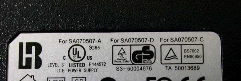
Click to zoom
Application Details
- Equipment Class
- DTS - Digital Transmission System
- Date of Grant
- May 13, 2004
- Application Purpose
- Original Equipment
- Date of Application
- May 13, 2004
- Equipment Note
- 802.11 a+g Super A/G Intelligent WLAN Access Point
- Frequency Range
- 2412.00000000 - 2462.00000000
- Company
- Wistron NeWeb Corporation
- Country
- Taiwan
Documents & Files
Document Text
Text extracted from the exhibit documents filed with the FCC. Open a document above to read the original.
Users Manual
IEEE 802.11a+g Access Point User’s Guide IEEE 802.11A+G ACCESS POINT User’s Guide Version 1.0, April 2004 Page i Copyright Statement No part of this publication may be reproduced, stored in a retrieval system, or transmitted in any form or by any means, whether electronic, mechanical, photocopying, recording or otherwise without the prior writing of the publisher. Windows ™ 95/98/Me and Windows ™ 2000/XP are trademarks of Microsoft ® Corp. Pentium is trademark of Intel. All copyright reserved. 2 IEEE 802.11a+g Access Point User’s Guide Table of Contents Regulatory Information.............4 Introducing the 802.11A+G ACCESS POINT... 5 Overview of the 802.11 a+g Access Point ...............................................................5 802.11A+G ACCESS POINT Features....6 Network Configuration Examples.........7 As An Access Point..........................7 As A stand-alone repeater...............8 As A point to multi-points Bridge....8 Setting Up the device............................9 Static IP...........................................9 Automatic IP....................................9 Installing the 802.11A+G ACCESS POINT.10 What’s in the Box?...............................10 Connecting the Cables........................11 Configuration Steps Required for the 802.11A+G ACCESS POINT....................................11 Setting up a Windows PC or wireless client as DHCP clients........................................12 A Look at the Front Panel....................14 Connecting More Devices Through A Hub To The 802.11A+G ACCESS POINT..................15 Basic Configuration of the 802.11A+G ACCESS POINT........................................................16 Logging On...........................................17 Setup Wizard........................................17 Time Settings.................................18 Device IP Settings.........................18 Wireless SETTINGS........................20 Advanced Settings....................................26 Password Settings...............................26 System Management..........................26 MAC Filtering Settings........................29 SSID Settings......................................30 Wireless Settings................................31 Operational Mode................................32 Radius Settings...................................33 DoS Settings........................................35 Managing the 802.11A+G ACCESS POINT36 How to View the device Status..........36 How to View the System Log.............. 37 Wireless Client Table..........................37 Bridge Table........................................38 Radio Table.........................................39 Upgrading Firmware...........................40 How to Save or Restore Configuration Changes .............................................................41 How to reset the configuration to the factory default.................................................42 How to Reboot your 802.11A+G ACCESS POINT .............................................................43 What if you Forgot the Password?......43 Command Line Interface..........................44 General guidelines..............................44 Express Mode vs. Advanced Mode of operation .............................................................45 Conventions........................................45 List of Commands...............................46 Text Configuration....................................52 General guidelines..............................52 List of Sections...................................52 Product Specification...............................61 4 Regulatory Information Federal Communication Commission Interference Statement This equipment has been tested and found to comply with the limits for a Class B digital device, pursuant to Part 15 of the FCC Rules. These limits are designed to provide reasonable protection against harmful interference in a residential installation. This equipment generates, uses and can radiate radio frequency energy and, if not installed and used in accordance with the instructions, may cause harmful interference to radio communications. However, there is no guarantee that interference will not occur in a particular installation. If this equipment does cause harmful interference to radio or television reception, which can be determined by turning the equipment off and on, the user is encouraged to try to correct the interference by one of the following measures: - Reorient or relocate the receiving antenna. - Increase the separation between the equipment and receiver. - Connect the equipment into an outlet on a circuit different from that to which the receiver is connected. - Consult the dealer or an experienced radio/TV technician for help. FCC Caution: To assure continued compliance, (example - use only shielded interface cables when connecting to computer or peripheral devices) any changes or modifications not expressly approved by the party responsible for compliance could void the user’s authority to operate this equipment. This device complies with Part 15 of the FCC Rules. Operation is subject to the following two conditions: (1) This device may not cause harmful interference, and (2) this device must accept any interference received, including interference that may cause undesired operation. IMPORTANT NOTE: FCC Radiation Exposure Statement: This equipment complies with FCC radiation exposure limits set forth for an uncontrolled environment. This equipment should be installed and operated with minimum distance 20cm between the radiator & your body. This transmitter must not be co-located or operating in conjunction with any other antenna or transmitter. Introducing the 802.11A+G ACCESS POINT Overview of the 802.11 a+g Access Point The 802.11A+G ACCESS POINT is an access-point based on IEEE 802.11a+g based 2.4- GHz and 5 GHz radio technology. It contains an 802.11a+g and a full-duplex 10/100 LAN interfaces. The 802.11A+G ACCESS POINT ca…
Text truncated - open the document above for the full version.
External Photos
Page 1 CONSTRUCTION PHOTOS OF EUT Page 2 Page 3 Page 4
ID Label/Location Info
Label
Internal Photos
Page 1 CONSTRUCTION PHOTOS OF EUT Page 2 Page 3 Page 4 Page 5 Page 6 Page 7 Page 8 Page 9
Operational Description
FCC ID: NKRCAP-1 Report No. 930421L03 Operation Description The transmitter of the EUT (802.11 a+g Super A/G Intelligent WLAN Access Point) is powered by power adapter and connected with managing computer through RJ45 port. The antenna is Dipole with reversed antenna connector and Patch antenna with UFL antenna connector. Under normal use condition, the user has to keep at least 20cm separation distance between radiator and the body of the user. This device is a 802.11 a+g Super A/G Intelligent WLAN Access Point which operates in both of the 5GHz and 2.4GHz bands and can transmitting simultaneously, the maximum data rate could be 54Mbps. For more detailed instruction, please take a look at the user’s manual. FCC 15.407(c) states : The device shall automatically discontinue transmission in case of either absence of information to transmit or operational failure. These provisions are not intended to preclude the transmission of control or signaling information or the use of repetitive codes used by certain digital technologies to complete frame or burst intervals. Applicants shall include in their application for equipment authorization a description of hoe this requirement is met” Data transmission is always initiated by software, which is then pass down through the MAC, through the digital and analog baseband, and finally to the RF chip. Several special packets (ACKs, CTS, PSPoll, etc...) are initiated by the MAC. There are the only ways the digital baseband portion will turn on the RF transmitter, which it then turns off at the end of the packet. Therefore, the transmitter will be on only while one of the aforementioned packets are being transmitted.
RF Exposure Info
FCC ID: NKRCAP-1 Report No: SA930421L03 1 RF EXPOSURE REPORT REPORT NO.: SA930421L03 MODEL NO.: CAP-1 ACCORDING: FCC Guidelines for Human Exposure IEEE C95.1 APPLICANT: Wistron NeWeb Corp. ADDRESS: No. 10-1, Li-hsin Road I, Science-based Industrial Park, Hsinchu 300, Taiwan, R. O. C. ISSUED BY: Advance Data Technology Corporation LAB LOCATION: No. 19, Hwa Ya 2 nd Rd., Wen Hwa Tsuen, Kwei Shan Hsiang, Taoyuan Hsien 333, Taiwan, R.O.C FCC ID: NKRCAP-1 Report No: SA930421L03 2 RF Exposure Measurement (Mobile Device) 1. Introduction In this document, we try to prove the safety of radiation harmfulness to the human body for our product. The limit for Maximum Permissible Exposure (MPE) specified in FCC 1.1310 is followed. The Gain of the antenna used in this product is measured in a Fully Anechoic Chamber (FAC) calibrated for antenna measurement in ADT, and also the maximum total power input to the antenna is measured. Through the Friis transmission formula and the maximum gain of the antenna, we can calculate the distance, away from the product, where the limit of MPE is reached. Although the Friis transmission formula is a far field assumption, the calculated result of that is an over-prediction for near field power density. We will take that as the worst case to specify the safety range. 2. RF Exposure Limit According to FCC 1.1310: The criteria listed in the following table shall be used to evaluate the environmental impact of human exposure to radio-frequency (RF) radiation as specified in 1.1307(b) LIMITS FOR MAXIMUM PERMISSIBLE EXPOSURE (MPE) Frequency Range (MHz) Electric Field Strength (V/m) Magnetic Field Strength (A/m) Power Density (mW/cm 2 ) Average Time (minutes) (A)Limits For Occupational / Control Exposures 300-1500......F/3006 1500-100,000......56 (B)Limits For General Population / Uncontrolled Exposure 300-1500......F/15006 1500-100,000......1.030 F = Frequency in MHz FCC ID: NKRCAP-1 Report No: SA930421L03 3 3. Friis Formula Friis transmission formula : Pd = (Pout*G) / (4*pi*r 2 ) where Pd = power density in mW/cm 2 Pout = output power to antenna in mW G = gain of antenna in linear scale Pi = 3.1416 R = distance between observation point and center of the radiator in cm If we know the maximum Gain of the antenna and the total power input to the antenna, through the calculation, we will know the MPE value at distance 20cm. Ref. : David K. Cheng, Field and Wave Electromagnetics, Second Edition, Page 640, Eq. (11-133). 4 EUT Operating condition The software provided by Manufacturer enabled the EUT to transmit and receive data at lowest, middle and highest channel individually. 5. Classification The antenna of this product, under normal use condition, is at least 20cm away from the body of the user. Warning statement to the user for keeping at least 20cm or more separation distance with the antenna should be included in users manual. So, this device is classified as Mobile Device. FCC ID: NKRCAP-1 Report No: SA930421L03 4 6 Test Results 6.1 Antenna Gain The maximum Gain measured in Fully Anechoic Chamber are 2dBi or 1.584 (numeric) for 2.4GHz and 4.33dBi or 2.71 (numeric) for 5GHz 6.2 Output Power Into Antenna & RF Exposure value at distance 20cm: For 802.11b (2.4GHz Band): Channel Channel Frequency (MHz) Output Power to Antenna (mW) Power Density (mW/cm 2 ) Limit of Power Density (mW/cm 2 ) 1241263.0960.0201.0 6243779.4330.0251.0 11246263.0960.0201.0 For 802.11g (2.4GHz Band): Channel Channel Frequency (MHz) Output Power to Antenna (Mw) Power Density (Mw/cm 2 ) Limit of Power Density (Mw/cm 2 ) 1241250.1190.0161.0 6243770.7950.0221.0 11246250.1190.0161.0 6(Turbo)243766.8340.0211.0 For 802.11a (5.15~5.35GHz): Channel Channel Frequency (MHz) Output Power to Antenna (mW) Power Density (mW/cm 2 ) Limit of Power Density (mW/cm 2 ) 1518024.7740.0131.0 4524025.2350.0141.0 5526033.3430.0181.0 8532063.9730.0341.0 For 802.11a (5.725~5.850GHz): Channel Channel Frequency (MHz) Output Power to Antenna (mW) Power Density (mW/cm 2 ) Limit of Power Density (mW/cm 2 ) 9574570.7950.0381.0 11578589.3310.0481.0 13582566.8340.0361.0 FCC ID: NKRCAP-1 Report No: SA930421L03 5 For 802.11a (Turbo): Channel Channel Frequency (MHz) Output Power to Antenna (mW) Power Density (mW/cm 2 ) Limit of Power Density (mW/cm 2 ) 1521026.4200.0141.0 2525026.7300.0141.0 3529074.6400.0401.0 4576066.9880.0361.0 5580066.9880.0361.0
Test Report
FCC ID: NKRCAP-1 Report No.: RF930421L031Issued: May 5, 2004 FCC TEST REPORT REPORT NO.: RF930421L03 MODEL NO.: CAP-1 RECEIVED: April 20, 2004 TESTED: April 24 ~ May 4, 2004 APPLICANT: Wistron NeWeb Corp. ADDRESS: No. 10-1, Li-hsin Road I, Science-based Industrial Park, Hsinchu 300, Taiwan, R.O.C. ISSUED BY: Advance Data Technology Corporation LAB LOCATION: No.47 14th Ling, Chia Pau Tsuen, Linkou Hsiang, Taipei, Taiwan, R.O.C. This test report consists of 197 pages in total. It may be duplicated completely for legal use with the approval of the applicant. It should not be reproduced except in full, without the written approval of our laboratory. The client should not use it to claim product endorsement by any government agencies. The test results in the report only apply to the tested sample. 0528 ILAC MRA FCC ID: NKRCAP-1 Report No.: RF930421L032Issued: May 5, 2004 Table of Contents 1.CERTIFICATION .................................................................................................................... 6 2.SUMMARY OF TEST RESULTS............................................................................................ 7 3.GENERAL INFORMATION .................................................................................................. 10 3.1GENERAL DESCRIPTION OF EUT..................................................................................... 10 3.2DESCRIPTION OF TEST MODES....................................................................................... 11 3.3GENERAL DESCRIPTION OF APPLIED STANDARDS...................................................... 12 3.4DESCRIPTION OF SUPPORT UNITS................................................................................. 13 3.5CONFIGURATION OF SYSTEM UNDER TEST.................................................................. 13 4.TEST TYPES AND RESULTS (FOR PART 802.11b & 802.11g)......................................... 14 4.1CONDUCTED EMISSION MEASUREMENT....................................................................... 14 4.1.1LIMITS OF CONDUCTED EMISSION MEASUREMENT .................................................... 14 4.1.2TEST INSTRUMENTS ......................................................................................................... 14 4.1.3TEST PROCEDURES .......................................................................................................... 15 4.1.4DEVIATION FROM TEST STANDARD ................................................................................ 15 4.1.5TEST SETUP ....................................................................................................................... 16 4.1.6EUT OPERATING CONDITIONS......................................................................................... 16 4.1.7TEST RESULTS ................................................................................................................... 17 4.2RADIATED EMISSION MEASUREMENT............................................................................ 23 4.2.1LIMITS OF RADIATED EMISSION MEASUREMENT ......................................................... 23 4.2.2TEST INSTRUMENTS ......................................................................................................... 24 4.2.3TEST PROCEDURES .......................................................................................................... 25 4.2.4DEVIATION FROM TEST STANDARD ................................................................................ 25 4.2.5TEST SETUP ....................................................................................................................... 26 4.2.6EUT OPERATING CONDITIONS......................................................................................... 26 4.2.7TEST RESULTS ................................................................................................................... 27 4.36dB BANDWIDTH MEASUREMENT ................................................................................... 42 4.3.1LIMITS OF 6dB BANDWIDTH MEASUREMENT ................................................................ 42 4.3.2TEST INSTRUMENTS ......................................................................................................... 42 4.3.3TEST PROCEDURE ............................................................................................................43 4.3.4DEVIATION FROM TEST STANDARD ................................................................................ 43 4.3.5TEST SETUP ....................................................................................................................... 43 4.3.6EUT OPERATING CONDITIONS......................................................................................... 43 4.3.7TEST RESULTS ................................................................................................................... 44 4.4MAXIMUM PEAK OUTPUT POWER ................................................................................... 54 4.4.1LIMITS OF MAXIMUM PEAK OUTPUT POWER MEASUREMENT ................................... 54 4.4.2INSTRUMENTS.................................................................................................................... 54 4.4.1TEST PROCEDURES .......................................................................................................... 55 4.4.2DEVIATION FROM TEST STANDARD ................................................................................ 55 4.4.3TEST SETUP ....................................................................................................................... 55 4.4.4EUT OPERATING CONDITIONS......................................................................................... 55 4.4.3TEST RESULTS ................................................................................................................... 56 4.5POWER SPECTRAL DENSITY MEASUREMENT..................................................…
Text truncated - open the document above for the full version.
Test Setup Photos
FCC ID: NKRCAP-1 Report No.: RF930421L03195Issued: May 5, 2004 6. PHOTOGRAPHS OF THE TEST CONFIGURATION CONDUCTED EMISSION TEST FCC ID: NKRCAP-1 Report No.: RF930421L03196Issued: May 5, 2004 RADIATED EMISSION TEST
Contact Information
Applicant
William Su(Senior Director / System Engineering dept.)
Technical Contact
Advance Data Technology Corp.Ellis Wu
[email protected]+886-3-318-3232
No.19, Hwa Ya 2nd Rd. · Kueishan Taoyuan · Taiwan
Test Firm
Advance Data Technology CorporationStephen Chen
Technical Specifications
| # | Rule Parts | Frequency Range | Power Output |
|---|---|---|---|
| 1 | 15C | 2.41 GHz - 2.46 GHz | 79.00 mW |
Other Applications from Wistron NeWeb Corporation
NKR-ATTCGW453
Aug 25, 2026Enterprise product
Equipment Class
NII - Unlicensed National Information Infrastructure TXNKR-LS06B
Aug 24, 2026Touchscreen
Equipment Class
NII - Unlicensed National Information Infrastructure TXNKR-DWSZW
Aug 10, 2026Door/Window Sensor
Equipment Class
DXX - Part 15 Low Power Communication Device TransmitterNKR-TELE2
Jun 26, 2026TELE2
Equipment Class
NII - Unlicensed National Information Infrastructure TXNKR-VMC-SA525MAX
Jun 05, 2026NAD (Network Access Device)
Equipment Class
CXX - Communications Rcvr for use w/ licensed Tx and CBs