NKRCB9GPWLAN a+b+g Cardbus Adapter
Wistron NeWeb Corporation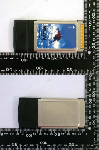
Click to zoom
Application Details
- Equipment Class
- NII - Unlicensed National Information Infrastructure TX
- Date of Grant
- Nov 08, 2005
- Application Purpose
- Original Equipment
- Date of Application
- Sep 23, 2005
- Equipment Note
- WLAN a+b+g Cardbus Adapter
- Frequency Range
- 5745.00000000 - 5805.00000000
- Company
- Wistron NeWeb Corporation
- Country
- Taiwan
Documents & Files
Document Text
Text extracted from the exhibit documents filed with the FCC. Open a document above to read the original.
Users Manual
Applicant: Wistron NeWeb Corporation FCC ID: NKRCB9GP Model: CB8-GP FCC Radiation Exposure Statement This equipment complies with FCC radiation exposure limits set forth for an uncontrolled environment. This transmitter must not be co-located or operating in conjunction with any other antenna or transmitter. The maximum reported SAR values are: Body: 0.752W/Kg (802.11a), 0.769W/Kg (802.11b), 0.489W/Kg (802.11g)
Users Manual
WLAN a+b+g Cardbus Adapter Model CB9-GP User Manual Version: 1.0 Dec. 2003 1 Copyright Statement No part of this publication may be reproduced, stored in a retrieval system, or transmitted in any form or by any means, whether electronic, mechanical, photocopying, recording or otherwise without the prior writing of the publisher. Windows ™ 98SE/2000/ME/XP are trademarks of Microsoft ® Corp. Pentium is trademark of Intel. All copyright reserved. 2 Federal Communication Commission Interference Statement This equipment has been tested and found to comply with the limits for a Class B digital device, pursuant to Part 15 of the FCC Rules. These limits are designed to provide reasonable protection against harmful interference in a residential installation. This equipment generates, uses and can radiate radio frequency energy and, if not installed and used in accordance with the instructions, may cause harmful interference to radio communications. However, there is no guarantee that interference will not occur in a particular installation. If this equipment does cause harmful interference to radio or television reception, which can be determined by turning the equipment off and on, the user is encouraged to try to correct the interference by one of the following measures: - Reorient or relocate the receiving antenna. - Increase the separation between the equipment and receiver. - Connect the equipment into an outlet on a circuit different from that to which the receiver is connected. - Consult the dealer or an experienced radio/TV technician for help. This device complies with Part 15 of the FCC Rules. Operation is subject to the following two conditions: (1) This device may not cause harmful interference, and (2) This device must accept any interference received, including interference that may cause undesired operation. Information to User To assure continued compliance, any changes or modifications not expressly approved by the party responsible for compliance could void the user’s authority to operate this equipment. IMPORTANT NOTE This equipment complies with FCC radiation exposure limits set forth for an uncontrolled environment. End users must follow the specific operation instruction for satisfying RF exposure compliance. This transmitter must not be co-located or operating in conjunction with any other antenna or transmitter. The maximum reported SAR values are: Body: 0.752W/Kg (802.11a), 0.769W/Kg (802.11b), 0.489W/Kg (802.11g) 3 Table of Contents 1. INTRODUCTION 4 1.1 KIT CONTENTS........................................................................................................4 1.2 SYSTEM REQUIREMENTS.........................................................................................4 1.3 STAT US LED ............................................................................................................4 2. DRIVER/UTILITY INSTALLATION / UNINSTALLATION 5 2.1 INSTALLATION.........................................................................................................5 2.1.1 ADDITIONAL SETUP PROCESSES.............................................................................8 2.1.2 VERIFYING THE DRIVER.........................................................................................8 2.2 UNINSTALLATION...................................................................................................10 3. CONNECTING TO AN EXISTING NETWORK 11 3.1 ADDITIONAL NOTE FOR WINDOWS XP .................................................................15 4. CREATING AN AD HOC NEW NETWORK 16 5. MODIFYING A WIRELESS NETWORK 19 5.1 I NFRASTRUCTURE MODE VS. AD HOC MODE......................................................19 5.2 MODIFYING A WIRELESS NETWORK.....................................................................20 5.3 DEFAULT SETTINGS WINDOWS XP ZERO-CONFIGURATION................................27 5.4 SUPER A/G SETTING..............................................................................................27 APPENDIX A: TROUBLESHOOTING 28 APPENDIX B: SPECIFICATION 32 4 1. Introduction Thank you for purchasing the WLAN a+b+g Cardbus Adapter that provides the easiest way to wireless networking. This User Manual contains detailed instructions in the operation of this product. Please keep this manual for future reference. 1.1 Kit Contents z WLAN a+b+g Cardbus Adapter z Installation Software CD z Quick Start Guide 1.2 System Requirements z A laptop PC contains: - 32-bit Cardbus slot (or Desktop PC with PC Card-PCI adapter) - 32 MB memory or greater - 300 MHz processor or higher z Microsoft ® Win ™ 2000/ME/98 Second Edition/XP 1.3 Status LED There are 2 Status LEDs on the WLAN a+b+g Cardbus Adapter. You can check your network connectivity status by looking at the LEDs. z Off: Power off. z Slow Blink: A connection is made. There is no activity yet. z Fast Blink: There are activities in a connected network. z Alternate Blink between LEDs: Look for a network association. z One LED Blink: Power Saving Mode is on. z One LED Steady Light: Awake from Power Saving Mode. 5 2. Driver/Utility Installation / Uninstallation 2.1 Installation Note! The Installation Section in this User Manual describes the first-time installation for Windows. To re-install the driver, please first uninstall the previously installed driver. See Chapter 2.2 “Uninstallation” section in this User Manual. Note! Do Not insert the Adapter into the Cardbus slot before the driver installation. Note! If you have inserted the Adapter into the Cardbus slot before installing the driver, a warning message pops up informing you that the software has not yet been installed. Please click “Cancel” to close the warning message. Remove the Adapter, and then start to install the driver. Follow the steps below to complete the driver/utility installation: 1. Insert the Installation Software CD into the CD-Rom Drive. 2. Click “Next”. 6 3. Read the License Agreement and click “Yes”. 4. Click “Next” to continue or clic…
Text truncated - open the document above for the full version.
Cover Letter(s)
Wistron Neweb Corporation No. 10-1, Li-hsin Road 1, Science-based Industrial Park,Hsinchu 300, Taiwan, R. O. C. Tel: 886-3-666-7799 Fax: 886-3-666-1654 Rev 2 C:\tmp\05LR025 CB9-GP\AP FORM.doc 02/08/02 Letter Of Agency Date: Sep. 15, 2005 Federal Communications Commission Authorization and Evaluation Division 7435 Oakland Mills Road Columbia, MD. 21046 U. S. A. To Whom It May Concern: We, the undersigned, hereby authorize International Standards Laboratory (ISL) of Taiwan, to act on our behalf in all matters relating to applications for equipment authorization, including the signing of all documents relating to these matters and payment required by FCC. Any and all acts carried out by ISL on our behalf shall have the same effect as our own. We certify that we are not subject to denial of federal benefits that includes FCC benefits, pursuant to Section 5301 of the Anti-Drug Abuse ACT of 1988, U.S.C. 862. Further, no party as defined in 47 CFR 1.2002(b), for this application is subject to denial of federal benefits that includes FCC benefits. Thank you for your attention to this matter. ________________ Mr. Edward Yeh / Engineer Wistron NeWeb Corporation Wistron Neweb Corporation No. 10-1, Li-hsin Road 1, Science-based Industrial Park,Hsinchu 300, Taiwan, R. O. C. 886-3-666-7799 886-3-666-1654 Rev 2 C:\tmp\05LR025 CB9-GP\AP FORM.doc 02/08/02 Date: Sep. 15, 2005 Federal Communications Commission Authorization and Evaluation Division 7435 Oakland Mills Road Columbia, MD. 21046 U. S. A. RE: Certification Application FCC ID: NKRCB9GP Model: CB9-GP We would like to apply for FCC Certification on the subject model (EUT). The EUT is a 802.11 a+b+g Wireless Cardbus Adapter. We have uploaded the related document for the EUT onto your website. Please review the information we submitted and issue us a grant for the subject model. If you have any comments, please do not hesitate to contact us. Thank you for your attention to these matters. Sincerely, ________________ Mr. Edward Yeh / Engineer Wistron NeWeb Corporation Wistron Neweb Corporation No. 10-1, Li-hsin Road 1, Science-based Industrial Park,Hsinchu 300, Taiwan, R. O. C. 886-3-666-7799 886-3-666-1654 Rev 2 C:\tmp\05LR025 CB9-GP\AP FORM.doc 02/08/02 FCC Labeling Requirements and Information Date: Sep. 15, 2005 Federal Communications Commission Authorization and Evaluation Division 7435 Oakland Mills Road Columbia, MD. 21046 U. S. A. RE: Certification Application FCC ID: NKRCB9GP Model: CB9-GP The following label information is required by the FCC Rules and Regulations for certified devices. Please find marketing information required by the FCC Rules and Regulations as following: Label Requirements An intentional radiator device subject to certification by the FCC shall carry a warning label which includes the following statement: This device complies with Part 15 of the FCC Rules. Operation is subject to the following two conditions: (1) this device may not cause harmful interference, and (2) this device must accept any interference received, including interference that may cause undesired operation. (Due to the space limitation, the statement is listed on page 2 of the users’ manual) The sample label shown shall be permanently affixed at a conspicuous location on the device and be readily visible to the user at the time of purchase. Sincerely, ________________ Mr. Edward Yeh / Engineer Wistron NeWeb Corporation FCC ID: NKRCB9GP Wistron Neweb Corporation No. 10-1, Li-hsin Road 1, Science-based Industrial Park,Hsinchu 300, Taiwan, R. O. C. 886-3-666-7799 886-3-666-1654 Rev 2 C:\tmp\05LR025 CB9-GP\AP FORM.doc 02/08/02 Request for Confidentiality Date: Sep. 15, 2005 Federal Communications Commission Authorization and Evaluation Division 7435 Oakland Mills Road Columbia, MD. 21046 U. S. A. RE: Certification Application FCC ID: NKRCB9GP Model: CB9-GP Please be advised that the following information is to be held confidential on behalf of Wistron NeWeb Corporation: Block Diagram Schematics Technical Spec The application contains technical information which Wistron NeWeb Corporation deems to be trade secrets and proprietary. If made public, the information might be used to the disadvantage of the applicant in the market place. Thank you for your attention to this matter. Sincerely, ________________ Mr. Edward Yeh / Engineer Wistron NeWeb Corporation
Cover Letter(s)
No. 65, Ku Dai Keng St., Hsichih, Taipei 221, R.O. C. Tel: 886-2-2646-2550 FAX: 886-2-26464641 No. 120, Lane 180, San Ho Tsuen, Hsin Ho Rd. Lung-Tan Hsiang, Tao Yuan County 325, Taiwan, R.O.C. Tel: 886-3-407-1718 FAX:886-3-407-1738 Date: Nov. 3 rd , 2005 Page 1 of 2 Re: FCC ID NKRCB9GP Applicant: Wistron NeWeb Corporation Correspondence Reference Number: 29862 731 Confirmation Number: EA128270 Dear Mr. Steven Dayhoff, Here are our answers, 1). Thank you for your information egarding future probe tip diameter requirement. If possible, please inform us how to get the detailed information regarding " Additional system validation checks if larger probes are used." 2). The SAR liquid is from Aprel Laboratories. 5800MHz Head Tissue Part No.: ALS-TS-5800-1-H Ingredient Water (de-ionized 16Mohm resistivity) Sugar HEC Preventol 5800MHz Body Tissue Part No.: ALS-TS-5800-1-B Ingredient Water (de-ionized 16Mohm resistivity) Sugar HEC Preventol 5200MHz Head Tissue Part No.: ALS-TS-5200-1-H Ingredient Water (de-ionized 16Mohm resistivity) Sugar HEC Preventol No. 65, Ku Dai Keng St., Hsichih, Taipei 221, R.O. C. Tel: 886-2-2646-2550 FAX: 886-2-26464641 No. 120, Lane 180, San Ho Tsuen, Hsin Ho Rd. Lung-Tan Hsiang, Tao Yuan County 325, Taiwan, R.O.C. Tel: 886-3-407-1718 FAX:886-3-407-1738 Page 1 of 2 5200MHz Body Tissue Part No.: ALS-TS-5200-1-B Ingredient Water (de-ionized 16Mohm resistivity) Sugar HEC Preventol 2450MHz Head Tissue Part No.: ALS-TS-2450-1-H Ingredient Water (de-ionized 16Mohm resistivity) DGBE (Di(ethylene glycol) butyl ether, [2-(2-butoxyethixy)ethanol]. Salt (> 99% pure NaCL) 2450MHz Body Tissue Part No.: ALS-TS-2450-1-B Ingredient Water (de-ionized 16Mohm resistivity) DGBE (Di(ethylene glycol) butyl ether, [2-(2-butoxyethixy)ethanol]. Salt (> 99% pure NaCL) Please review the information we submitted Thnaks Daphne Liu International Standards Laboratory
Cover Letter(s)
No. 65, Ku Dai Keng St., Hsichih, Taipei 221, R.O. C. Tel: 886-2-2646-2550 FAX: 886-2-26464641 No. 120, Lane 180, San Ho Tsuen, Hsin Ho Rd. Lung-Tan Hsiang, Tao Yuan County 325, Taiwan, R.O.C. Tel: 886-3-407-1718 FAX:886-3-407-1738 Date: Nov. 3 rd , 2005 Page 1 of 2 Re: FCC ID NKRCB9GP Applicant: Wistron NeWeb Corporation Correspondence Reference Number: 29862 731 Confirmation Number: EA128270 Dear Mr. Steven Dayhoff, Here are our answers, 1). Thank you for your information egarding future probe tip diameter requirement. If possible, please inform us how to get the detailed information regarding " Additional system validation checks if larger probes are used." 2). The SAR liquid is from Aprel Laboratories. 5800MHz Head Tissue Part No.: ALS-TS-5800-1-H Ingredient Water (de-ionized 16Mohm resistivity) Sugar HEC Preventol 5800MHz Body Tissue Part No.: ALS-TS-5800-1-B Ingredient Water (de-ionized 16Mohm resistivity) Sugar HEC Preventol 5200MHz Head Tissue Part No.: ALS-TS-5200-1-H Ingredient Water (de-ionized 16Mohm resistivity) Sugar HEC Preventol No. 65, Ku Dai Keng St., Hsichih, Taipei 221, R.O. C. Tel: 886-2-2646-2550 FAX: 886-2-26464641 No. 120, Lane 180, San Ho Tsuen, Hsin Ho Rd. Lung-Tan Hsiang, Tao Yuan County 325, Taiwan, R.O.C. Tel: 886-3-407-1718 FAX:886-3-407-1738 Page 1 of 2 5200MHz Body Tissue Part No.: ALS-TS-5200-1-B Ingredient Water (de-ionized 16Mohm resistivity) Sugar HEC Preventol 2450MHz Head Tissue Part No.: ALS-TS-2450-1-H Ingredient Water (de-ionized 16Mohm resistivity) DGBE (Di(ethylene glycol) butyl ether, [2-(2-butoxyethixy)ethanol]. Salt (> 99% pure NaCL) 2450MHz Body Tissue Part No.: ALS-TS-2450-1-B Ingredient Water (de-ionized 16Mohm resistivity) DGBE (Di(ethylene glycol) butyl ether, [2-(2-butoxyethixy)ethanol]. Salt (> 99% pure NaCL) Please review the information we submitted Thnaks Daphne Liu International Standards Laboratory
External Photos
International Standards Laboratory Report Number: ISL-05LR025P HC LAB:NVLAP:200234-0;VCCI: R-341,C-354;NEMKO:ELA 113a,113c;BSMI:SL2-IN-E-0037;SL2-R1-E-0037;CNLA:1178 LT LAB:NVLAP:200234-0;VCCI: R-1435,C-1440;NEMKO:ELA 113b,113d;BSMI:SL2-IN-E-0013;CNLA:0997 -1- EUT-1.
ID Label/Location Info
Label Location location
RF Exposure Info
Report Number: 05LR025SAR-F Issue Date: 2005/09/08 HC LAB:NVLAP:200234-0;VCCI: R-341,C-354;NEMKO:ELA 113a,113c;BSMI:SL2-IN-E-0037;SL2-R1-E-0037;CNLA:1178 LT LAB:NVLAP:200234-0;VCCI: R-1435,C-1440;NEMKO:ELA 113b,113d;BSMI:SL2-IN-E-0013;CNLA:0997 ISL-T10-R31-1 SAR Test Report Of Product Name 802.11 a+b+g Wireless Cardbus Adapter Model CB9-GP (Brand: Wistron Neweb) Applied by: Wistron Neweb Corporation No. 10-1, Li-hsin Road 1, Science-based Industrial Park,Hsinchu 300, Taiwan, R. O. C. Test Performed by: International Standards Laboratory No. 120, Lane 180, San Ho Tsuen, Hsin Ho Rd. Lung-Tan Hsiang, Tao Yuan County 325 Taiwan, R.O.C. Tel:(03)407-1718 Fax:(03)407-1738 International Standards Laboratory Report Number: 05LR025SAR-F HC LAB:NVLAP:200234-0;VCCI: R-341,C-354;NEMKO:ELA 113a,113c;BSMI:SL2-IN-E-0037;SL2-R1-E-0037;CNLA:1178 LT LAB:NVLAP:200234-0;VCCI: R-1435,C-1440;NEMKO:ELA 113b,113d;BSMI:SL2-IN-E-0013;CNLA:0997 -i- Contents of Report 1. General ......................................................................................................... 3 1.1 Certification of Accuracy of Test Data ........................................................................ 3 2. Description of Equipment Under Test (EUT) .............................................. 2 2.1 Test Environment ......................................................................................................... 3 3. SAR Measurement System........................................................................... 4 3.1 ALSAS-10U System Description ................................................................................. 4 3.2 Isotropic E-Field Probe................................................................................................. 5 3.3 Boundary Detection Unit and Probe Mounting Device ............................................... 7 3.4 Daq-Paq (Analog to Digital Electronics) ..................................................................... 8 3.5 Axis Articulated Robot................................................................................................. 8 3.6 ALSAS Universal Workstation .................................................................................... 9 3.7 Universal Device Positioner ......................................................................................... 9 3.8 Phantom Types ............................................................................................................. 9 4. Tissue Simulating Liquid ........................................................................... 11 4.1 The composition of the tissue simulating liquid......................................................... 11 4.2 Tissue Calibration Result ........................................................................................... 11 4.3 Tissue Dielectric Parameters for Head and Body Phantoms ...................................... 13 5. SAR Measurement Procedure .................................................................... 14 5.1 SAR System Validation.............................................................................................. 14 5.2 SAR Measurement Procedure .................................................................................... 16 6. SAR Exposure Limits................................................................................. 17 7. Test Equipment List ................................................................................... 18 8. Measurement Uncertainty .......................................................................... 19 9. Test Result Summary ................................................................................. 20 9.1 802.11b Test Result ................................................................................................... 20 9.2 802.11g Test Result ................................................................................................... 20 9.3 802.11a (5150MHz ~5350MHz, Normal Mode) Test Result ................................... 21 9.4 802.11a (5150MHz ~5350MHz, Turbo Mode) Test Result ..................................... 21 9.5 802.11a (5725MHz ~5825MHz, Normal Mode) Test Result ................................... 22 9.6 802.11a (5725MHz ~5825MHz, Turbo Mode) Test Result ..................................... 22 10. SAR System Validation Data ..................................................................... 23 10.1 2450MHz System Validation Data ........................................................................ 23 10.2 5200 MHz System Validation Data ....................................................................... 27 10.3 5800 MHz System Validation Data ....................................................................... 30 11. 2450MHz SAR measurement Data ............................................................ 33 11.1 802.11b, Right Antenna .......................................................................................... 34 11.2 802.11b, Left Antenna............................................................................................. 39 11.3 802.11g, Right Antenna .......................................................................................... 44 11.4 802.11g, Left Antenna............................................................................................. 49 11.5 2450MHz Z-Axis plot ............................................................................................ 54 12. 5200 MHz SAR measurement Data ........................................................... 56 12.1 802.11a (5150MHz ~5350MHz, Normal Mode), Right Antenna........................... 57 12.2 802.11a (5150MHz ~5350MHz, Normal Mode), Left Antenna ............................. 63 12.3 802.11a (5150MHz ~5350MHz, Turbo Mode), Right Antenna ............................. 69 International Standards Laboratory Report Number: 05LR025SAR-F HC LAB:NVLAP:200234-0;VCCI: R-341,C-354;NEMKO:ELA 113a,113c;BSMI:SL2-IN-E-0037;SL2-R…
Text truncated - open the document above for the full version.
RF Exposure Info
NCL Calibration Laboratories Division of APREL Laboratories. This page has been reviewed for content and attested to by signature within this document. 3 Calibration Results Summary The following results relate the Calibrated Dipole and should be used as a quick reference for the user. Mechanical Dimensions Length: 51.5 mm Height: 30.4 mm Electrical Specification SWR: 1.01 U Return Loss: -45.3 dB Impedance: 50.6 Ω System Validation Results Frequency 1 Gram 10 Gram Peak 2450 MHz 53.09 24.44 101.85 NCL Calibration Laboratories Division of APREL Laboratories. This page has been reviewed for content and attested to by signature within this document. 4 Introduction This Calibration Report has been produced in line with the SSI Dipole Calibration Procedure SSI-TP-018-ALSAS. The results contained within this report are for Validation Dipole 2450-220-00753. The calibration routine consisted of a three-step process. Step 1 was a mechanical verification of the dipole to ensure that it meets the mechanical specifications. Step 2 was an Electrical Calibration for the Validation Dipole, where the SWR, Impedance, and the Return loss were assessed. Step 3 involved a System Validation using the ALSAS-10U, along with APREL E-020 130 MHz to 26 GHz E-Field Probe Serial Number 212. References SSI-TP-018-ALSAS Dipole Calibration Procedure SSI-TP-016 Tissue Calibration Procedure IEEE 1528 “Recommended Practice for Determining the Peak Spatial-Average Specific Absorption Rate (SAR) in the Human Body Due to Wireless Communications Devices: Experimental Techniques” Conditions Dipole 2450-220-00753 was new taken from stock. Ambient Temperature of the Laboratory: 22 °C +/- 0.5°C Temperature of the Tissue: 20 °C +/- 0.5°C NCL Calibration Laboratories Division of APREL Laboratories. This page has been reviewed for content and attested to by signature within this document. 5 Dipole Calibration Results Mechanical Verification APREL Length APREL Height Measured Length Measured Height 51.5 mm 30.4 mm 52.1 mm 31.0 mm Tissue Validation Head Tissue 2450 MHz Measured Dielectric constant, ε r 39.2 Conductivity, σ [S/m] 1.80 NCL Calibration Laboratories Division of APREL Laboratories. This page has been reviewed for content and attested to by signature within this document. 6 Electrical Calibration Test Result S11 R/L -45.3 dB SWR 1.01 U Impedance 50.6 Ω The Following Graphs are the results as displayed on the Vector Network Analyzer. S11 Parameter Return Loss NCL Calibration Laboratories Division of APREL Laboratories. This page has been reviewed for content and attested to by signature within this document. 7 SWR NCL Calibration Laboratories Division of APREL Laboratories. This page has been reviewed for content and attested to by signature within this document. 8 Smith Chart Dipole Impedance NCL Calibration Laboratories Division of APREL Laboratories. This page has been reviewed for content and attested to by signature within this document. 9 System Validation Results Using the Electrically Calibrated Dipole Head Tissue Frequency 1 Gram 10 Gram Peak Above Feed Point 2450 MHz 53.09 24.44 101.85 NCL Calibration Laboratories Division of APREL Laboratories. This page has been reviewed for content and attested to by signature within this document. 10 Test Equipment The test equipment used during Probe Calibration, manufacturer, model number and, current calibration status are listed and located on the main APREL server R:\NCL\Calibration Equipment\Instrument List May 2004
RF Exposure Info
NCL CALIBRATION LABORATORIES Calibration File No.: CP-571 Client.: Wistron C E R T I F I C A T E OF C A L I B R A T I O N It is certified that the equipment identified below has been calibrated in the NCL CALIBRATION LABORATORIES by qualified personnel following recognized procedures and using transfer standards traceable to NRC/NIST. Equipment: Miniature Isotropic RF Probe 2450 MHz Manufacturer: APREL Laboratories Model No.: E-020 Serial No.: 266 Calibration Procedure: SSI/DRB-TP-D01-032-E020-V2 Project No: WISB-ALSAS10U-5121 Calibrated: 24 th March 2005 Released on: 28 th March 2005 This Calibration Certificate is Incomplete Unless Accompanied with the Calibration Results Summary Released By: ______________________________________________________ NCL CALIBRATION LABORATORIES 51 SPECTRUM WAY Division of APREL Lab. NEPEAN, ONTARIO TEL: (613) 820-4988 CANADA K2R 1E6 FAX: (613) 820-4161 NCL Calibration Laboratories Division of APREL Laboratories. Page 2 of 10 This page has been reviewed for content and attested to on Page 2 of this document. Introduction This Calibration Report reproduces the results of the calibration performed in line with the SSI/DRB-TP-D01-032-E020-V2 E-Field Probe Calibration Procedure. The results contained within this report are for APREL E-Field Probe E-020 266. References SSI/DRB-TP-D01-032-E020-V2 E-Field Probe Calibration Procedure IEEE 1528 “Recommended Practice for Determining the Peak Spatial-Average Specific Absorption Rate (SAR) in the Human Body Due to Wireless Communications Devices: Experimental Techniques” SSI-TP-011 Tissue Calibration Procedure Conditions Probe 266 was a new probe taken from stock prior to calibration. Ambient Temperature of the Laboratory: 22 °C +/- 0.5°C Temperature of the Tissue: 21 °C +/- 0.5°C We the undersigned attest that to the best of our knowledge the calibration of this probe has been accurately conducted and that all information contained within this report has been reviewed for accuracy. ------------------------------------------------------------ Stuart Nicol ------------------------------------------------------------ Y. Chen NCL Calibration Laboratories Division of APREL Laboratories. Page 3 of 10 This page has been reviewed for content and attested to on Page 2 of this document. Calibration Results Summary Probe Type: E-Field Probe E-020 Serial Number: 266 Frequency: 2450 MHz Sensor Offset: 1.56 mm Sensor Length: 2.5 mm Tip Enclosure: Ertalyte* Tip Diameter: <5 mm Tip Length: 60 mm Total Length: 290 mm *Resistive to recommended tissue recipes per IEEE-1528 Sensitivity in Air Channel X: 1.2 μV/(V/m) 2 Channel Y: 1.2 μV/(V/m) 2 Channel Z: 1.2 μV/(V/m) 2 Diode Compression Point: 95 mV NCL Calibration Laboratories Division of APREL Laboratories. Page 4 of 10 This page has been reviewed for content and attested to on Page 2 of this document. Sensitivity in Head Tissue Frequency: 2450 MHz Epsilon: 39.2 (+/-5%) Sigma: 1.80 S/m (+/-5%) ConvF Channel X: 4.9 Channel Y: 4.9 Channel Z: 4.9 Tissue sensitivity values were calculated using the load impedance of the APREL Laboratories Daq-Paq. Boundary Effect: Uncertainty resulting from the boundary effect is less than 2% for the distance between the tip of the probe and the tissue boundary, when less than 2.44mm. Spatial Resolution: The measured probe tip diameter is 5 mm (+/- 0.01 mm) and therefore meets the requirements of SSI/DRB-TP-D01-032 for spatial resolution. NCL Calibration Laboratories Division of APREL Laboratories. Page 5 of 10 This page has been reviewed for content and attested to on Page 2 of this document. Receiving Pattern 2450 MHz (Air) Receiving Pattern Probe s/n 266 2450MHz 0 0.2 0.4 0.6 0.8 1 1.2 0 10 20 30 40 50 60 70 80 90 100 110 120 130 140 150 160 170 180 190 200 210 220 230 240 250 260 270 280 290 300 310 320 330 340 350 Ch1Ch2Ch3Tot NCL Calibration Laboratories Division of APREL Laboratories. Page 6 of 10 This page has been reviewed for content and attested to on Page 2 of this document. Isotropy Error 2450 MHz (Air) Isotropy Error Probe s/n 266 2450MHz -10 -9 -8 -7 -6 -5 -4 -3 -2 -1 0 1 2 3 4 5 6 7 8 9 10 0100200300 Error [dB] Isotropy Plot Probe s/n 266 2450MHz 0 0.1 0.2 0.3 0.4 0.5 0.6 0.7 0.8 0100200300 Degrees (x10) Voltage (mV) Ch1Ch2Ch3 Isotropicity in Tissue: 0.10 dB NCL Calibration Laboratories Division of APREL Laboratories. Page 7 of 10 This page has been reviewed for content and attested to on Page 2 of this document. Dynamic Range Probe 266 Dynamic Range 0.01 0.1 1 10 100 1000 10000 1.0010.00100.001,000.0010,000.00100,000.001,000,000.0010,000,000.00 Electric Field [(V/m)^2] Voltage [microV] Uncompensated Compensated NCL Calibration Laboratories Division of APREL Laboratories. Page 8 of 10 This page has been reviewed for content and attested to on Page 2 of this document. Video Bandwidth Probe Frequency Characteristics -6 -5 -4 -3 -2 -1 0 1 110100100010000 Frequency (Hz) Video Bandwidth at 500 Hz 1 dB Video Bandwidth at 1.02 KHz: 3 dB NCL Calibration Laboratories Division of APREL Laboratories. Page 9 of 10 This page has been reviewed for content and attested to on Page 2 of this document. Conversion Factor Uncertainty Assessment Frequency: 2450MHz Epsilon: 39.2 (+/-5%) Sigma: 1.80 S/m (+/-5%) ConvF Channel X: 4.9 7%(K=2) Channel Y: 4.9 7%(K=2) Channel Z: 4.9 7%(K=2) To minimize the uncertainty calculation all tissue sensitivity values were calculated using a load impedance of 5 MΩ. Boundary Effect: For a distance of 2.4mm the evaluated uncertainty (increase in the probe sensitivity) is less than 2%. NCL Calibration Laboratories Division of APREL Laboratories. Page 10 of 10 This page has been…
Text truncated - open the document above for the full version.
Contact Information
Applicant
William Su(Senior Director / System Engineering dept.)
Technical Contact
AmericanTCBWilliam H Graff
[email protected]703 847 4700
6731 Whittier Avenue · McLean, Virginia · United States
Non-Technical Contact
International Standards LaboratoryDaphne Liu
[email protected]+886 2 2646 2550
Test Firm
International Standards LaboratoryDavid Wu
Technical Specifications
| # | Rule Parts | Frequency Range | Power Output |
|---|---|---|---|
| 2 | 15E | 5.75 GHz - 5.80 GHz | 35.00 mW |
Other Applications from Wistron NeWeb Corporation
NKR-ATTCGW453
Aug 25, 2026Enterprise product
Equipment Class
NII - Unlicensed National Information Infrastructure TXNKR-LS06B
Aug 24, 2026Touchscreen
Equipment Class
NII - Unlicensed National Information Infrastructure TXNKR-DWSZW
Aug 10, 2026Door/Window Sensor
Equipment Class
DXX - Part 15 Low Power Communication Device TransmitterNKR-TELE2
Jun 26, 2026TELE2
Equipment Class
NII - Unlicensed National Information Infrastructure TXNKR-VMC-SA525MAX
Jun 05, 2026NAD (Network Access Device)
Equipment Class
CXX - Communications Rcvr for use w/ licensed Tx and CBs