NKRDRCBBCM 4318 CF Module
Wistron NeWeb Corporation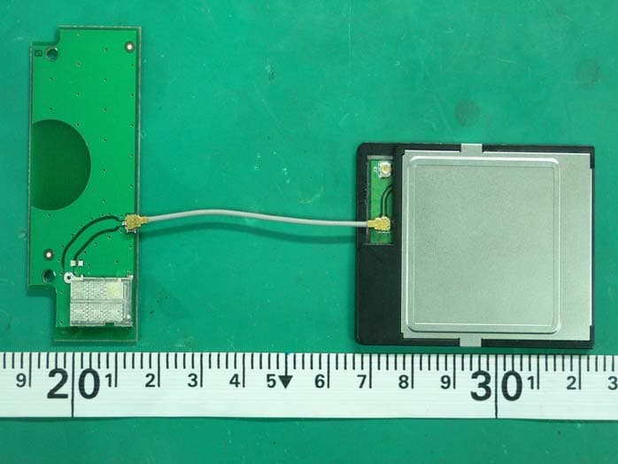
Click to zoom
Application Details
- Equipment Class
- DTS - Digital Transmission System
- Date of Grant
- Dec 28, 2005
- Application Purpose
- Original Equipment
- Date of Application
- Dec 28, 2005
- Equipment Note
- BCM 4318 CF Module
- Frequency Range
- 2412.00000000 - 2462.00000000
- Company
- Wistron NeWeb Corporation
- Country
- Taiwan
Documents & Files
Document Text
Text extracted from the exhibit documents filed with the FCC. Open a document above to read the original.
Users Manual
DRCB-M1 IEEE 802.11 b/g CF WLAN Module User’s Manual V0.1 Dec.20, 2005 1 Table of Contents Chapter 1 Functional Description ................................................... 5 1.1 Features ............................................................................. 5 1.2 Integrated Radio Transceiver ............................................. 5 1.3 Receiver Path..................................................................... 6 1.4 Transmitter Path ................................................................. 6 1.5 Calibration .......................................................................... 6 Chapter 2 Installation Driver ........................................................... 7 2.1 Driver Features................................................................... 7 2.2 Installing the driver ............................................................. 7 2 Copyright Statement No part of this publication may be reproduced, stored in a retrieval system, or transmitted in any form or by any means, whether electronic, mechanical, photocopying, recording or otherwise without the prior writing of the publisher. Windows ™ 98SE/2000/ME/XP are trademarks of Microsoft ® Corp. Pentium is trademark of Intel. All copyright reserved. FEDERAL COMMUNICATIONS COMMISSION This device complies with Part 15 of the FCC Rules. Operation is subject to the following two conditions:(1) this device may not cause harmful interference, and (2) this device must accept any interference received, including interference that may cause undesired operation. This equipment has been tested and found to comply with the limits for a Class B digital device, pursuant to Part 15 of the FCC Rules. These limits are designed to provide reasonable protection against harmful interference in a residential installation. This equipment generates, uses and can radiated radio frequency energy and, if not installed and used in accordance with the instructions, may cause harmful interference to radio communications. However, there is no guarantee that interference will not occur in a particular installation If this equipment does cause harmful interference to radio or television reception, which can be determined by turning the equipment off and on, the user is encouraged to try to correct the interference by one or more of the following measures: -Reorient or relocate the receiving antenna. -Increase the separation between the equipment and receiver. -Connect the equipment into an outlet on a circuit different from that to which the receiver is connected. -Consult the dealer or an experienced radio/TV technician for help. Changes or modifications not expressly approved by the party responsible for compliance could void the user‘s authority to operate the equipment. This device is intended only for OEM integrators under the following conditions: 1) The antenna must be installed such that 20 cm is maintained between the antenna and users, and 2) The transmitter module may not be co-located with any other transmitter or antenna. As long as 2 conditions above are met, further transmitter test will not be required. However, the OEM integrator is still responsible for testing their end-product for any additional compliance requirements required with this module installed (for example, digital device emissions, PC peripheral requirements, etc.). IMPORTANT NOTE: In the event that these conditions can not be met (for example certain laptop configurations or co-location with another transmitter), then the FCC authorization is no longer considered valid and the FCC ID can not be used on the final product. In these circumstances, the OEM integrator will be responsible for re-evaluating the end product (including the transmitter) and obtaining a separate FCC authorization. The antenna cable can only be connected on J2 port. If the FCC ID is not visible when the module is installed inside another device, then the outside of the device into which the module is installed must also display a label referring to the enclosed module. This exterior label can use wording such as the following: “Contains FCC ID: NKRDRCB” . 5 Chapter 1 Functional Description Thank you very much for purchasing this IEEE802.11b/g CF WLAN Module. This product provides the easiest way to wireless networking. This User Manual contains instructions in the operation of this product. Please keep this manual for future reference. 1.1 Features Includes Encore signal processing for Industry-leading receive sensitivity and extended range: . -74 dBm at 54Mbps . -76 dBm with external LNA High level of integration with direct converseon radio architecture minimizes external circuitry, leading to lowest cost, lowest power, and smallest footprint implementation Flexible support for a variety of system bus interfaces includeing: PCI, Mini PCI, CardBus, PCMCIA/Compact Flash, and SDIO (4-wire, 1-wire, and SPI) Programmable data rates of 1, 2, 5.5, 6, 9, 11, 12, 18, 24, 36, 48, and 54 Mbps. 24-bit IV and 40-bit/104-bit key WEP encryption support System support for 128-bit AES IEEE802.1x support Dynamic Power Management under driver control WHQL-certified drivers for Windows® XP/Me/2000/98SE/98 operating systems Wi-Fi® compliant 1.2 Integrated Radio Transceiver This CF module includes an integrated RF transceiver that has been optimized for use in 2.4-GHz WLAN systems. It has been designed to provide low-power, low-cost, and robust communications for applications operating in the globally available 2.4-GHz unlicensed ISM band. With an external transmit power amplifyier, it develops full output power per 6 the IEEE802.11b/g Specification. 1.3 Receiver Path This CF module has a wide dynamic range, direct conversion receiver. It employs high-order on-chip channel filtering to ensure reliable operation in the noisy 2.4-GHz ISM band. The excellent noise figure of the receiver makes an external LNA unnecessary. Leading-edge Encore DSP technology improves the re…
Text truncated - open the document above for the full version.
Cover Letter(s)
Page No. : 6 Module Approval Request Letter Subject: Module Approval Date: 2005/12/26 FCC ID: NKRDRCB Dear Reviewer, We, Sporton International Inc., are authorized by Wistron NeWeb Corporation to have their state-of-the-art BCM4318 CF module approved under limited module approval authorization. The application of this module is specified to Mobile host equipment. The requirements regulated in Public Notice DA00-1407 have been fulfilled and clearly explained below. 1. The requirement of RF shielding: The shielding of the radio portion can be demonstrated in exhibition External Photo. 2. The requirement of buffered inputs: Buffered data inputs stage has been integrated in chip BCM4318E. 3. The requirement of power supply regulation: The part number of the power regulator is AME8805MEFT . 4. The requirements of section 15.203 and 15.204(C): The requirements of antenna connector and spurious emission have been fulfilled. Please reference the exhibition Test Report. 5. The requirement of stand-alone test configuration: Please reference exhibition Test Configuration Photo for the stand-alone test configuration. 6. The requirement of labeling: The instruction on the labeling rule of the end product has been stated in the users manual of this module. Please also see the exhibition Label Sample. 7. The requirement of compliance on specific rule or operating requirements: The required FCC rule has been fulfilled and all the instructions for maintaining compliance has been clearly stated in the Users Manual. 8. The requirement of RF exposure: Please refer exhibition RF Exposure for the compliance of RF exposure rule. Please do not hesitate to contact me for any questions of this request letter. Thank you. Company name : Sporton International Inc. Company Address : No. 52, Hwa Ya 1st Road., Kwei-Shan Hsiang, TaoYuan Hsien Taiwan R.O.C. Signature : Name : Wayne Hsu Job Title : Supervisor
Cover Letter(s)
Page No. : 6 Module Approval Request Letter Subject: Module Approval Date: 2005/12/6 FCC ID: NKRDBUB-A1 Dear Reviewer, We, Sporton International Inc., are authorized by Wistron NeWeb Corporation to have their state-of-the-art BRCM 2045 bluetooth module approved under module approval authorization. The requirements regulated in Public Notice DA00-1407 have been fulfilled and clearly explained below. 1. The requirement of RF shielding: The shielding of the radio portion can be demonstrated in exhibition External Photo. 2. The requirement of buffered inputs: Buffered data inputs stage has been integrated in chip BCM2045NMD. 3. The requirement of power supply regulation: The part number of the power regulator is SST39LF200A . 4. The requirements of section 15.203 and 15.204(C): The requirements of antenna connector and spurious emission have been fulfilled. Please reference the exhibition Test Report. 5. The requirement of stand-alone test configuration: Please reference exhibition Test Configuration Photo for the stand-alone test configuration. 6. The requirement of labeling: The instruction on the labeling rule of the end product has been stated in the users manual of this module. Please also see the exhibition Label Sample. 7. The requirement of compliance on specific rule or operating requirements: The required FCC rule has been fulfilled and all the instructions for maintaining compliance has been clearly stated in the Users Manual. 8. The requirement of RF exposure: Please refer exhibition RF Exposure for the compliance of RF exposure rule. The output power is very low, there is no concern on the RF Exposure. Company name : Sporton International Inc. Company Address : No. 52, Hwa Ya 1st Road., Kwei-Shan Hsiang, TaoYuan Hsien Taiwan R.O.C. Signature : Name : Wayne Hsu Job Title : Supervisor
External Photos
SPORTON International Inc. PAGE NUMBER : A1 OF A9 TEL : 886-2-2696-2468 ISSUED DATE : Dec,28,2005 FAX : 886-2-2696-2255 APPENDIX A. Photographs of EUT SPORTON International Inc. PAGE NUMBER : A2 OF A9 TEL : 886-2-2696-2468 ISSUED DATE : Dec,28,2005 FAX : 886-2-2696-2255 SPORTON International Inc. PAGE NUMBER : A3 OF A9 TEL : 886-2-2696-2468 ISSUED DATE : Dec,28,2005 FAX : 886-2-2696-2255 SPORTON International Inc. PAGE NUMBER : A4 OF A9 TEL : 886-2-2696-2468 ISSUED DATE : Dec,28,2005 FAX : 886-2-2696-2255 SPORTON International Inc. PAGE NUMBER : A5 OF A9 TEL : 886-2-2696-2468 ISSUED DATE : Dec,28,2005 FAX : 886-2-2696-2255
ID Label/Location Info
SPORTON International Inc. PAGE NUMBER : A4 OF A8 TEL : 886-2-2696-2468 ISSUED DATE : Dec,28,2005 FAX : 886-2-2696-2255
Internal Photos
SPORTON International Inc. PAGE NUMBER : A6 OF A9 TEL : 886-2-2696-2468 ISSUED DATE : Dec,28,2005 FAX : 886-2-2696-2255 SPORTON International Inc. PAGE NUMBER : A7 OF A9 TEL : 886-2-2696-2468 ISSUED DATE : Dec,28,2005 FAX : 886-2-2696-2255 SPORTON International Inc. PAGE NUMBER : A8 OF A9 TEL : 886-2-2696-2468 ISSUED DATE : Dec,28,2005 FAX : 886-2-2696-2255 SPORTON International Inc. PAGE NUMBER : A9 OF A9 TEL : 886-2-2696-2468 ISSUED DATE : Dec,28,2005 FAX : 886-2-2696-2255
Operational Description
Opreational Description Date: 2005/12/28 EUT is a BCM4318 CF module with 11 channels(2412MHz~2462MHz, Space 5MHz). It allows you to connect to other WLAN device. General Operational Description: 1. Time base of the transmission frequency: For IF and RF frequency, Crystal is a clock reference. 2. Synthesizer: Synthesizer inside Transceiver IC and operate frequency in 2.4GHz ISM Band. Internal voltage controlled oscillator (VCO) provides the desired LO signal base on the phase-locked loop (PLL) with a relatively wide tuning range for this application. 3. Transmission: BBP IC has DSSS (BPSK/QPSK/CCK) and OFDM (BPSK/QPSK/16QAM/64QAM) modulation function, it provides transmission data rate are 1, 2, 5.5, 11 Mbps on DSSS and 6, 12, 18, 24, 36, 48, 54 Mbps on OFDM. Digital data signal will be converted to analog (TX IQ) signals through DAC in BBP IC, TX IQ pass through to low pass filter. TX I/Q signal use direct conversion (zero-IF) architecture converter to generate carrier frequency signal. Transceiver IC and external PA magnify output power. 4. Receiver: Reverse direction isolation of LNA inside Transceiver IC suppresses unwanted radiation. Then 2.4GHz RF signal will be directly down to IF signal (RX IQ) and high frequency spurious emissions are suppressed by LPF. At last RX IQ signal will be demodulated digital data. 5. Base band Processing: Channel Selection: Channel selection is controlled by BBP IC. Data Modulation: DSSS (BPSK/QPSK/CCK) and OFDM (BPSK/QPSK/16QAM/64QAM) modulation type is controlled by BBP IC. Power Control Level: BBP IC has the power leveling loop table are calibrated by manufacturer, then uses closed-loop power control function to limit RF output power level. Power leveling step accuracy is ±0.5dB. Transmit/Receive Switch: EUT has Transmit/Receive Switch and Antenna switch Data Link Layer: Firmware implements the full IEEE 802.11 Wireless LAN MAC protocol. It supports BSS and IBSS operation under DCF, and operation under the optional Point Coordination Function (PCF). Lower level protocol functions such as RTS/CTS generation and acknowledgment, fragmentation and de-fragmentation, and automatic beacon monitoring are handled without host intervention. Active scanning is performed autonomously once initiated by host command. Host interface command and status handshakes allow concurrent operations from multi-threaded I/O drivers. 6. Interface: CF 7. Power: Input 3.3Vdc from host equipment. This power is provided to regulator components to regulated DC power. Report No.: FR5D1908 Report Format Version: RF-15.247-a Page No. : 3 of 52 FCC ID: NKRDRCB Issued Date : Dec. 27, 2005 3. GENERAL INFORMATION 3.1. Product Details EUT IS a CF module with IEEE 802.11b/g radio function. Only the radio detail of WLAN is shown in the table below. For more detailed features description, please refer to the manufacturer’s specifications or user’s manual. Items Description Product Type WLAN Radio Type Intentional Transceiver Power Type Host Interface Type CF Modulation DSSS for IEEE 802.11b ; OFDM for IEEE 802.11g Data Modulation DSSS (BPSK / QPSK / CCK) ; OFDM (BPSK / QPSK / 16QAM / 64QAM) Data Rate (Mbps) DSSS (1/ 2/ 5.5/11) ; OFDM (6/9/12/18/24/36/48/54) Frequency Range 2400 ~ 2483.5MHz Channel Number 11 Channel Band Width (99%) 11b: 12.60 MHz ; 11g: 16.44 MHz Conducted Output Power 11b: 17.90 dBm ; 11g: 18.90 dBm Carrier Frequencies 2412-2462 MHz Antenna Chip Antenna 3.2. Accessories NA 3.3. Table for Filed Antenna Ant. Brand Model Name Antenna Type Connector Gain (dBi) 1 TENNA EA2400 Chip Antenna UFL 3.00
Operational Description
Operational Description Date: 2005/12/12 EUT is a BRCM 2045 bluetooth module with 79 channels(2402~2480MHz, Space 1MHz). It allows you to connect to other Bluetooth device. General Operational Description: 1. Time base of the transmission frequency: For IF and RF frequency, Crystal is a clock reference. 2. Synthesizer: Synthesizer inside Bluetooth (Transceiver/BBP) single chip IC and operate frequency in 2.4GHz ISM Band. Internal voltage controlled oscillator (VCO) provides the desired LO signal base on the phase-locked loop (PLL) with a relatively wide tuning range for this application. 3. Transmission: Bluetooth IC has FHSS (GFSK) modulation function, it provides transmission data rate are 1 Mbps. Digital data signal will be converted to analog (TX IQ) signals through DAC in Bluetooth IC, TX IQ pass through to low pass filter of Bluetooth IC. TX I/Q signal use direct conversion (zero-IF) architecture converter to generate carrier frequency signal. Bluetooth IC has a power amplifier to magnify output power. 4. Receiver: Reverse direction isolation of LNA inside Bluetooth IC suppresses unwanted radiation. Then 2.4GHz RF signal will be directly down to IF signal (RX IQ) and high frequency spurious emissions are suppressed by LPF. At last RX IQ signal will be demodulated digital data. 5. Base band Processing: Channel hopping: Automatic hopping channel is controlled by Bluetooth IC. Data Modulation: FHSS (GFSK) modulation type is controlled by Bluetooth IC. Power Control Level: Bluetooth IC has the power leveling loop table are calibrated by manufacturer, then uses closed-loop power control function to limit RF output power level. Power leveling step accuracy is ± 0.5dB. The typical out power is class 2~3. Transmit/Receive Switch: Not-applicable Data Link Layer: It supports BlueCore Serial Protocol (BCSP), Dynamic UART configuration. On-chip RAM of Bluetooth IC allows full speed Bluetooth data transfer, mixed voice and data. Transcoders for A-law, μ-law and linear voice from host and A-law, μ-law and CVSD voice over air. It dedicates logic for forward error correction, header error control, access code correlation, demodulation, cyclic redundancy check, encryption bitstream generation. 6. Interface: Not-applicable 7. Power: Input 3.3Vdc from host equipment. This power is provided to regulator components to regulated DC power. Report No.: FR5N2310 Report Format Version: RF-15.247-a Page No. : 3 of 46 FCC ID: NKRDBUB-A1 Issued Date : Dec. 9, 2005 3. GENERAL INFORMATION 3.1. Product Details EUT IS a BRCM 2045 bluetooth module with Bluetooth radio functions. Only the radio detail of Bluetooth is shown in the table below. For more detailed features description, please refer to the manufacturer’s specifications or user’s manual. Items Description Radio Type Intentional Transceiver Power Type 3.3V DC from host Interface Type NA Modulation FHSS (GFSK / QPSK /8PPSK) Data Rate (Mbps) GFSK: 1 ; QPSK: 2 ; 8PSK: 3 Frequency Range 2400 ~ 2483.5MHz Channel Number 79 Channel Band Width (99%) 1164 kHz Conducted Output Power 0.17 dBm Carrier Frequencies 2402-2480 MHz Antenna Chip Antenna 3.2. Table for Filed Antenna Ant. Model Name Antenna Type Connector Gain (dBi) 1 U.FL-R-SMT Chip Antenna Hirose 1.0 3.3. Table for Carrier Frequencies Freqeuncy Band Channel No. Frequency 0 2402 MHz 1 2403 MHz : : 38 2440 MHz 39 2441 MHz 40 2442 MHz : : 77 2479 MHz 2400~2483.5MHz 78 2480 MHz
RF Exposure Info
Report No.: 5D1908 FCC ID: NKRDRCB Page No. : 1 of 3 Appendix C. Maximum Permissible Exposure Report No.: 5D1908 FCC ID: NKRDRCB Page No. : 2 of 3 1. Maximum Permissible Exposure 1.1. Applicable Standard Systems operating under the provisions of this section shall be operated in a manner that ensures that the public is not exposed to radio frequency energy levels in excess limit for maximum permissible exposure. In accordance with 47 CFR FCC Part 2 Subpart J, section 2.1091 this device has been defined as a mobile device whereby a distance of 20 cm normally can be maintained between the user and the device. (A) Limits for Occupational / Controlled Exposure Frequency Range (MHz) Electric Field Strength (E) (V/m) Magnetic Field Strength (H) (A/m) Power Density (S) (mW/ cm²) Averaging Time |E|²,|H|² or S (minutes) 0.3-3.0 614 1.63 (100)* 6 3.0-30 1842 / f 4.89 / f (900 / f)* 6 30-300 61.4 0.163 1.0 6 300-1500 F/300 6 1500-100,000 5 6 (B) Limits for General Population / Uncontrolled Exposure Frequency Range (MHz) Electric Field Strength (E) (V/m) Magnetic Field Strength (H) (A/m) Power Density (S) (mW/ cm²) Averaging Time |E|²,|H|² or S (minutes) 0.3-1.34 614 1.63 (100)* 30 1.34-30 824/f 2.19/f (180/f)* 30 30-300 27.5 0.073 0.2 30 300-1500 F/1500 30 1500-100,000 1.0 30 Note: f = frequency in MHz ; *Plane-wave equivalent power density 1.2. MPE Calculation Method E (V/m) = d GP××30 Power Density: Pd (mW/cm²) = 377 2 E E = Electric field (V/m) P = Peak RF output power (mW) G = EUT Antenna numeric gain (numeric) d = Separation distance between radiator and human body (cm) The formula can be changed to Pd = 2 377 30 d GP × ×× From the peak EUT RF output power, the minimum mobile separation distance, d=20cm, as well as the gain of the used antenna, the RF power density can be obtained. Report No.: 5D1908 FCC ID: NKRDRCB Page No. : 3 of 3 1.3. Calculated Result and Limit Antenna Type : Chip Antenna Max Conducted Power for IEEE 802.11b/g : 20dBm Antenna Gain (dBi) Antenna Gain (numeric) Peak Output Power (dBm) Peak Output Power ( mW ) Power Density (S) (mW/cm²) Limit of Power Density (S) (mW/cm²) Test Result 3 1.9953 18.9000 77.6247 0.030828 1 Complies
Test Report
SPORTON International Inc. No. 52, Hwa Ya 1st Rd., Kwei-Shan Hsiang, TaoYuan Hsien, Taiwan, R.O.C. Ph: 886-3-327-3456 / FAX: 886-3-327-0973 / www.sporton.com.tw Report Format Version: RF-15.247-a FCC RADIO TEST REPORT Applicant’s company Wistron NeWeb Corporation Applicant Address No. 10-1, Li-hsin Road I, Science-based Industrial Park, Hsinchu 300, Taiwan, R.O.C. FCC ID NKRDRCB Manufacturer’s company Wistron NeWeb Corporation Manufacturer Address No. 10-1, Li-hsin Road I, Science-based Industrial Park, Hsinchu 300, Taiwan, R.O.C. Product Name BCM4318 CF module Brand Name Wistron NeWeb Model Name DRCB-M1 Test Rule Part(s) 47 CFR FCC Part 15 Subpart C § 15.247 Test Freq. Range 2400 ~ 2483.5MHz Receive Date Dec. 19, 2005 Test Date Dec. 26, 2005 Submission Type Original Equipment Statement Test result included is only for the 802.11b/g part of the product. The test result in this report refers exclusively to the presented test model / sample. Without written approval of SPORTON International Inc., the test report shall not be reproduced except in full. The measurements and test results shown in this test report were made in accordance with the procedures and found in compliance with the limit given in ANSI C63.4-2003 and 47 CFR FCC Part 15 Subpart C. The test equipment used to perform the test is calibrated and traceable to NML/ROC. Lab Code: 200079-0 Report No.: FR5D1908 Report Format Version: RF-15.247-a Page No. : i of ii FCC ID: NKRDRCB Issued Date : Dec. 27, 2005 Table of Contents 1. CERTIFICATE OF COMPLIANCE.......................................................................................................................... 1 2. SUMMARY OF THE TEST RESULT........................................................................................................................... 2 3. GENERAL INFORMATION................................................................................................................................... 3 3.1. Product Details....................................................................................................................................................................................3 3.2. Accessories.........................................................................................................................................................................................3 3.3. Table for Filed Antenna.......................................................................................................................................................................3 3.4. Table for Carrier Frequencies...............................................................................................................................................................4 3.5. Table for Test Modes............................................................................................................................................................................4 3.6. Table for Testing Locations...................................................................................................................................................................4 3.7. Table for Supporting Units....................................................................................................................................................................5 3.8. Table for Parameters of Test Software Setting.......................................................................................................................................5 3.9. Test Configurations..............................................................................................................................................................................6 4. TEST RESULT...................................................................................................................................................... 8 4.1. AC Power Line Conducted Emissions Measurement............................................................................................................................8 4.2. Maximum Peak Output Power Measurement....................................................................................................................................13 4.3. Power Spectral Density Measurement...............................................................................................................................................15 4.4. 6dB Spectrum Bandwidth Measurement...........................................................................................................................................20 4.5. Radiated Emissions Measurement.....................................................................................................................................................25 4.6. Band Edge Emissions Measurement..................................................................................................................................................43 4.7. Antenna Requirements......................................................................................................................................................................48 5. LIST OF MEASURING EQUIPMENTS.................................................................................................................... 49 6. SPORTON COMPANY PROFILE......................................................................................................................... 51 6.1. Test Location.....................................................................................................................................................................................51 7. CERTIFICATE OF NVLAP ACCREDITATION.......................................................................................................... 52 APPENDIX A. PHOTOGRAPHS OF EUT ............................................................................................................. A1 ~ A8…
Text truncated - open the document above for the full version.
Test Setup Photos
Report No.: FR5D1908 FCC ID: NKRDRCB Page No. : 1 of 3 Appendix B. Test Photos Report No.: FR5D1908 FCC ID: NKRDRCB Page No. : 2 of 3 1. Photographs of Conducted Emissions Test Configuration FRONT VIEW REAR VIEW Report No.: FR5D1908 FCC ID: NKRDRCB Page No. : 3 of 3 2. Photographs of Radiated Emissions Test Configuration FRONT VIEW REAR VIEW
Contact Information
Applicant
William Su(Senior Director / System Engineering dept.)
Technical Contact
Sporton International IncWayne Hsu
[email protected]+886 3 327 3456
No. 52, Hwa Ya 1st Rd. Kwei Shan · Tao Yuan · Taiwan
Test Firm
Sporton International Inc.Kathy Lin
Technical Specifications
| # | Rule Parts | Frequency Range | Power Output |
|---|---|---|---|
| 1 | 15C | 2.41 GHz - 2.46 GHz | 77.63 mW |
Other Applications from Wistron NeWeb Corporation
NKR-ATTCGW453
Aug 25, 2026Enterprise product
Equipment Class
NII - Unlicensed National Information Infrastructure TXNKR-LS06B
Aug 24, 2026Touchscreen
Equipment Class
NII - Unlicensed National Information Infrastructure TXNKR-DWSZW
Aug 10, 2026Door/Window Sensor
Equipment Class
DXX - Part 15 Low Power Communication Device TransmitterNKR-TELE2
Jun 26, 2026TELE2
Equipment Class
NII - Unlicensed National Information Infrastructure TXNKR-VMC-SA525MAX
Jun 05, 2026NAD (Network Access Device)
Equipment Class
CXX - Communications Rcvr for use w/ licensed Tx and CBs