NKRKTHDP1JVC HD Radio PnP
Wistron NeWeb Corporation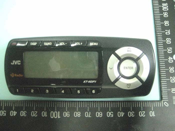
Click to zoom
Application Details
- Equipment Class
- DXX - Part 15 Low Power Communication Device Transmitter
- Date of Grant
- Aug 08, 2007
- Application Purpose
- Original Equipment
- Date of Application
- Aug 07, 2007
- Equipment Note
- JVC HD Radio PnP
- Frequency Range
- 88.10000000 - 107.90000000
- Company
- Wistron NeWeb Corporation
- Country
- Taiwan
Documents & Files
Document Text
Text extracted from the exhibit documents filed with the FCC. Open a document above to read the original.
Users Manual
High Definition Radio Plug & Play Model: KT-HDP1 Installation & User Guide 2007 May 2 Warning and Safety Information FCC Warning This equipment may generate or use radio frequency energy. Changes or modifications to this equipment may cause harmful interference unless the modifications are expressly approved in this user guide. The user could lose the authority to operate this equipment if an unauthorized change or modification is made. FCC Compliance This equipment has been tested and found to comply with the limits for a Class B digital device, pursuant to Part 15 of the FCC Rules. These limits are designed to provide reasonable protection against harmful interference in a residential installation. This equipment generates, uses and can radiate radio frequency energy and, if not installed and used in accordance with the instructions, may cause harmful interference to radio communications. However, there is no guarantee that interference will not occur in a particular installation. If this equipment does cause harmful interference to radio or television reception, which can be determined by turning the equipment off and on, the user is encouraged to try to correct the interference by one of the following measures: Reorient or relocate the receiving antenna. Increase the separation between the equipment and the receiver. Connect the equipment into an outlet on a circuit different from that to which the receiver is connected. Consult the dealer or an experienced radio technician for help. This device complies with Part 15 of the FCC Rules. Operation is subject to the following two conditions: (1) This device may not cause harmful interference, and (2) this device must accept any interference received, including interference that may cause undesired operation. This device and its antenna(s) must not be co-located or operation in conjunction with any other antenna or transmitter. 3 General Precautions Liquid Crystal Precautions If the LCD screen on the receiver is damaged, do not to touch the liquid crystal fluid. If any of the following situations happen, take the action indicated: . If the liquid crystal fluid comes in contact with your skin, wipe the skin area with a cloth and then wash the skin thoroughly with soap and running water. . If the liquid crystal fluid gets into your eye, flush the eye with clean water for at least 15 minutes. Seek medical care. . If the liquid crystal fluid is ingested, flush your mouth thoroughly with water. Drink large quantities of water and induce vomiting. Seek medical care. Safety Precautions Be sure to observe the following warnings. Failure to follow these safety instructions and warnings may result in a serious accident. . Do not operate the receiver in a way that might divert your attention from driving safely. As a driver, you alone are responsible for safely operating your vehicle in accordance with traffic safety laws at all times. . Do not install the receiver where it may obstruct your view through the windshield, or of your vehicle’s indicator displays. . Do not install the receiver where it may hinder the function of safety devices such as an airbag. Doing so may prevent the airbag from functioning properly in the event of an accident. . Be sure the receiver and accessories are installed as described in the installation instructions which accompany each accessory kit. . To avoid short circuits, do not open the receiver or accessories, and never put or leave any metallic objects (coins, tools, etc.) inside the receiver. . If the receiver or accessories emits smoke or unusual odors, turn the power off immediately, and disconnect the receiver from any power source. . Do not drop the receiver or subject it to strong shocks. . If the receiver doesn’t seem to be working properly, turn the receiver off, wait 10 seconds, replace the battery and then turn it 4 on again. The installation and use suggestions contained in this manual are subject to any restrictions or limitations that may be imposed by applicable law. The purchaser should check applicable law for any restrictions or limitations before installing and/or operating this unit. Warnings Operating Temperature The receiver is designed to operate between –20 o C to +85 o C. Avoid leaving the receiver in a vehicle or elsewhere where the temperature may fall outside this range. Extreme temperatures or extreme temperature fluctuations can degrade the performance of the LCD display screen, and possibly damage it. Cleaning and Maintenance If the receiver or accessories become dirty, turn the power off and wipe it clean with a soft cloth. Do not use hard cloths, strong cleaning fluids, paint thinner, alcohol, or other volatile solvents to clean. These may cause damage to the receiver. 5 Package Contents HD Radio Receiver Remote Controller Car Cradle Relay Box 6 Installation Professional installation provides an experienced technician to install this product in your vehicle, advice for selecting a suitable mounting location, installation of the antenna, and routing all the necessary wires and cables. If the FM reception within your vehicle proves to be poor, an installer will have the necessary accessories to install an optional FM Relay Switch, or an audio cable, to connect the audio output of the dock directly to your vehicle’s audio system. Installing the Vehicle Docking Station When installing the vehicle docking station in your vehicle, choose a location in your vehicle where it will not block your vision, interfere with the vehicle controls, or obstruct the air bag. The location should be easily accessible and provide good visibility of the display, and should not be located where it will be in direct sunlight which will affect the visibility of the display screen. Connecting the Cigarette Lighter Adapter Connect the provided cigarette lighter adapter to the 12V DC connection at the rear of the dock. 7 Getting Started Controls 1 7 1 2 1 3 456 9 8 10 1. POWER Button: Turns the receiver On or Off.…
Text truncated - open the document above for the full version.
Cover Letter(s)
KDB Inquiry Tracking Number - 299505
Cover Letter(s)
SPORTON International Inc. No.8, Lane 724, Bo-ai St., Jhubei City, Hsinchu County 302, Taiwan, R.O.C. TEL: 886-3-656-9065 FAX: 886-3-656-9085 FCC Requested Information for 15.239 device FCC ID: NKRKTHDP1 1) How does this device operate? A: This device is a DAB (HD Radio) receiver; it receives the HD signal and then modulated as FM signal to either vehicle FM receiver by air or via a relay box by wire. These two ways of transmitting can only be used individually. 2) Provide information on the device and its antenna. A: This device is a DAB (HD Radio) receiver that includes: (1) One external FM transmitting antenna, (2) Two external HD Radio receiving antennas (these two antennas could only be used individually, (3) Cigarette Lighter Adapter, (4) Remote Controller, (5) Remote Cradle , (6) Relay Box, (7) RCA cable. 3) How is it installed? A: This device has to be installed by professional installer. The manufacturer did not give specific guide on the arrangement of the antenna. The user’s manual mentions that car cradle must be not block driver’s vision. 4) What test procedure was used? A: The system is tested according to the procedure in ANSI C63.4. Cables are manipulated on the tabletop to maximize the FM band signal level. And also, the cables are bundled as per the instruction in ANSI C63.4 and are then moved around to maximize the FM band signal. 5) If tested in a car, how was it configured/tested? A: It is not tested in the car. 6) Was the tuning range properly verified? The test lab should indicate in the report that the tuning controls were manually adjusted to verify maximum tuning range. A: The tuning controls were manually adjusted to verify maximum tuning range. All controls, manual and software were adjusted to determine the maximum tuning range capability of the unit. This range is specified in the test report and is 88.1MHz to 107.9MHz. 7) Was the bandwidth properly tested with maximum audio input? A: Maximum internal modulation was used since the radio doesn’t have an external audio input. The modulator audio input level control was set to maximum to perform this test. 8) Use a typical audio file from a typical device. e.g. do not use a 1 kHz signal from a signal generator. A: There is no any audio file used on the test since the maximum internal modulation was used.
External Photos
SPORTON International Inc. PAGE NUMBER : A1 OF A2 TEL : 886-2-2696-2468 ISSUED DATE : Jun. 12, 2007 FAX : 886-2-2696-2255 APPENDIX A. Photographs of EUT SPORTON International Inc. PAGE NUMBER : A2 OF A2 TEL : 886-2-2696-2468 ISSUED DATE : Jun. 12, 2007 FAX : 886-2-2696-2255
Internal Photos
SPORTON International Inc. PAGE NUMBER : A1 OF A9 TEL : 886-2-2696-2468 ISSUED DATE : Jun. 12, 2007 FAX : 886-2-2696-2255 APPENDIX A. Photographs of EUT SPORTON International Inc. PAGE NUMBER : A2 OF A9 TEL : 886-2-2696-2468 ISSUED DATE : Jun. 12, 2007 FAX : 886-2-2696-2255 SPORTON International Inc. PAGE NUMBER : A3 OF A9 TEL : 886-2-2696-2468 ISSUED DATE : Jun. 12, 2007 FAX : 886-2-2696-2255 SPORTON International Inc. PAGE NUMBER : A4 OF A9 TEL : 886-2-2696-2468 ISSUED DATE : Jun. 12, 2007 FAX : 886-2-2696-2255 SPORTON International Inc. PAGE NUMBER : A5 OF A9 TEL : 886-2-2696-2468 ISSUED DATE : Jun. 12, 2007 FAX : 886-2-2696-2255 SPORTON International Inc. PAGE NUMBER : A6 OF A9 TEL : 886-2-2696-2468 ISSUED DATE : Jun. 12, 2007 FAX : 886-2-2696-2255 SPORTON International Inc. PAGE NUMBER : A7 OF A9 TEL : 886-2-2696-2468 ISSUED DATE : Jun. 12, 2007 FAX : 886-2-2696-2255 SPORTON International Inc. PAGE NUMBER : A8 OF A9 TEL : 886-2-2696-2468 ISSUED DATE : Jun. 12, 2007 FAX : 886-2-2696-2255 SPORTON International Inc. PAGE NUMBER : A9 OF A9 TEL : 886-2-2696-2468 ISSUED DATE : Jun. 12, 2007 FAX : 886-2-2696-2255
Test Report
SPORTON International Inc. No. 52, Hwa Ya 1st Rd., Kwei-Shan Hsiang, TaoYuan Hsien, Taiwan, R.O.C. Ph: 886-3-327-3456 / FAX: 886-3-327-0973 / www.sporton.com.tw Report Format Version: 01 FCC RADIO TEST REPORT Applicant’s company Wistron NeWeb Corporation Applicant Address No. 10-1, Li-hsin Road I, Science-baded Industrial Park, Hsinchu 300, Taiwan, R.O.C. FCC ID NKRKTHDP1 Manufacturer’s company 1 Wistron NeWeb Corporation Manufacturer Address No. 10-1, Li-hsin Road I, Science-baded Industrial Park, Hsinchu 300, Taiwan, R.O.C. Manufacturer’s company 2 WNC (Kunshan) Corporation Manufacturer Address No. 88, Central Avenue, Area B, Kunshan Export Processing Zone, Kunshan City, Jiangsu, China Product Name JVC HD Radio PnP Brand Name JVC Model Name KT-HDP1 Test Rule Part(s) 47 CFR FCC Part 15 Subpart C § 15.239 Test Freq. Range 88 ~ 108MHz Received Date May 21, 2007 Final Test Date Jun. 10, 2007 Submission Type Original Equipment Statement The device is only possible within the range 88.1-107.9MHz. The test result in this report refers exclusively to the presented test model / sample. Without written approval of SPORTON International Inc., the test report shall not be reproduced except in full. The measurements and test results shown in this test report were made in accordance with the procedures and found in compliance with the limit given in ANSI C63.4-2003 and 47 CFR FCC Part 15 Subpart C. The test equipment used to perform the test is calibrated and traceable to NML/ROC. Report No.: FR752309 Report Format Version: 01 Page No. : i of ii FCC ID: NKRKTHDP1 Issued Date : Jun. 12, 2007 Table of Contents 1. CERTIFICATE OF COMPLIANCE ......................................................................................................................... 1 2. SUMMARY OF THE TEST RESULT .......................................................................................................................... 2 3. GENERAL INFORMATION .................................................................................................................................. 3 3.1. Product Details....................................................................................................................................................................................3 3.2. Accessories .........................................................................................................................................................................................3 3.3. Table for Filed Antenna.......................................................................................................................................................................4 3.4. Table for Carrier Frequencies .............................................................................................................................................................4 3.5. Table for Test Modes ...........................................................................................................................................................................5 3.6. Table for Testing Locations..................................................................................................................................................................5 3.7. Table for Supporting Units ...................................................................................................................................................................5 3.8. Test Configurations .............................................................................................................................................................................6 4. TEST RESULT ................................................................................................................................................... 10 4.1. Field Strength of Fundamental Emissions Measurement ...................................................................................................................10 4.2. 20dB Spectrum Bandwidth Measurement ........................................................................................................................................18 4.3. Radiated Emissions Measurement ....................................................................................................................................................21 4.4. Band Edge Emissions and Tuning Range of FM transmitter Measurement .......................................................................................31 4.5. Antenna Requirements .....................................................................................................................................................................35 5. LIST OF MEASURING EQUIPMENTS ................................................................................................................... 36 6. TEST LOCATION.............................................................................................................................................. 37 7. TAF CERTIFICATE OF ACCREDITATION ............................................................................................................. 38 APPENDIX A. PHOTOGRAPHS OF EUT.........................................................................................................A1 ~ A11 APPENDIX B. TEST PHOTOS.......................................................................................................................... B1 ~ B4 Report No.: FR752309 Report Format Version: 01 Page No. : ii of ii FCC ID: NKRKTHDP1 Issued Date : Jun. 12, 2007 History of This Test Report Original Issue Date: Jun. 12, 2007 Report No.: FR752309 ■ No additional attachment. □ Additional attachment were issued as following record: Attachment No. Issue Date Description 15.205(a) 15.209(a) 47 CFR FCC Part 15 Subpart C Further, this requirement does not apply to intentional radiators that must be professionally installed. Report No.: FR752309 Repo…
Text truncated - open the document above for the full version.
Test Setup Photos
Report No.: FR752309 FCC ID: NKRKTHDP1 Page No. : 1 of 4 Appendix B. Test Photos Report No.: FR752309 FCC ID: NKRKTHDP1 Page No. : 2 of 4 1. Photographs of Radiated Emissions Test Configuration 9kHz ~30MHz FRONT VIEW REAR VIEW Report No.: FR752309 FCC ID: NKRKTHDP1 Page No. : 3 of 4 30MHz~1GHz FRONT VIEW REAR VIEW Report No.: FR752309 FCC ID: NKRKTHDP1 Page No. : 4 of 4 88~108MHz FRONT VIEW REAR VIEW
Contact Information
Applicant
William Su(Senior Director / System Engineering dept.)
Test Firm
Sporton International Inc.Alex Chen
Technical Specifications
| # | Rule Parts | Frequency Range | Power Output |
|---|---|---|---|
| 1 | 15C | 88.1 MHz - 107.9 MHz | - |
Other Applications from Wistron NeWeb Corporation
NKR-ATTCGW453
Aug 25, 2026Enterprise product
Equipment Class
NII - Unlicensed National Information Infrastructure TXNKR-LS06B
Aug 24, 2026Touchscreen
Equipment Class
NII - Unlicensed National Information Infrastructure TXNKR-DWSZW
Aug 10, 2026Door/Window Sensor
Equipment Class
DXX - Part 15 Low Power Communication Device TransmitterNKR-TELE2
Jun 26, 2026TELE2
Equipment Class
NII - Unlicensed National Information Infrastructure TXNKR-VMC-SA525MAX
Jun 05, 2026NAD (Network Access Device)
Equipment Class
CXX - Communications Rcvr for use w/ licensed Tx and CBs