NKRMS2143CM6Notebook Personal Computer
Wistron NeWeb Corporation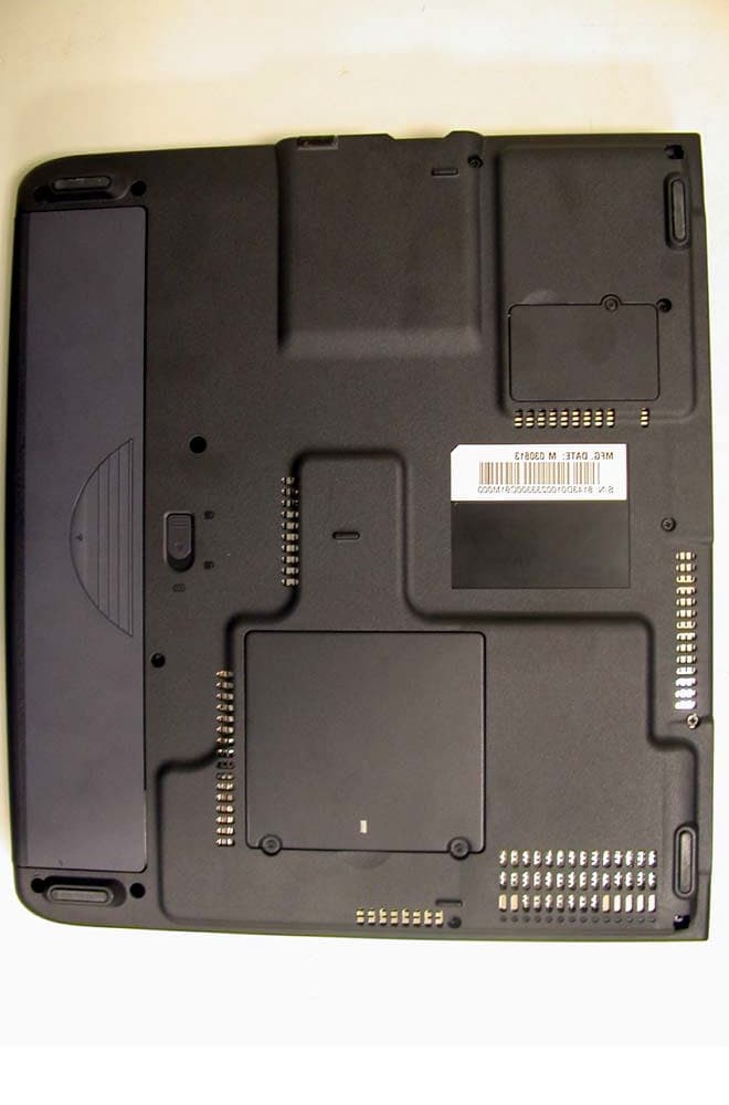
Click to zoom
Application Details
- Equipment Class
- NII - Unlicensed National Information Infrastructure TX
- Date of Grant
- Feb 23, 2004
- Application Purpose
- Original Equipment
- Date of Application
- Dec 24, 2003
- Equipment Note
- Notebook Personal Computer
- Frequency Range
- 5180.00000000 - 5805.00000000
- Company
- Wistron NeWeb Corporation
- Country
- Taiwan
Documents & Files
Document Text
Text extracted from the exhibit documents filed with the FCC. Open a document above to read the original.
Users Manual
Acer Aspire 1500 series User’s Guide Model MS2143 Changes may be made periodically to the information in this publication without obligation to notify any person of such revision or changes. Such changes will be incorporated in new editions of this manual or supplementary documents and publications. This company makes no representations or warranties, either expressed or implied, with respect to the contents hereof and specifically disclaims the implied warranties of merchantability or fitness for a particular purpose. Record the model number, serial number, purchase date, and place of purchase information in the space provided below. The serial number and model number are recorded on the label affixed to your computer. All correspondense concerning your unit should include the serial number, model number, and purchase information. No part of this publication may be reproduced, stored in a retrieval system, or transmitted, in any form or by any means, electronic, mechanical, photocopy, recording, or otherwise, without the prior written permission of Acer Incorporated. Model Number : _________________________________ Serial Number: ___________________________________ Purchase Date: ___________________________________ Place of Purchase: ________________________________ Copyright © 2003 All Rights Reserved Acer Aspire 1500 Series Notebook Computer User's Guide Original Issue: December 2003 Acer Aspire 1500 series Notebook computer All trademarks and registered trademarks are the properties of their respective companies. iii English English First things first Yo u r g u i d e s A set of guides is provided to help you set up and use your Aspire computer: For more information on Acer’s products, services, and support, please visit the web site: http:// www.acer.com. Basic care and tips for using your computer Turning your computer on and off To turn on your computer, open the lid and press the power button above the keyboard. To turn the power off, you can do any of the following: •Click on the Start button in Windows, and then select Shut Down on the popup menu. •Push the power button. To use this method, you must first click on the Power Management icon in Windows Control Panel, and then check that the power button is set to shut down the computer when pressed. See Windows Help for more information. The Just for starters... poster shows you how to set up your computer. This User's Guide provides clear and concise information on using your computer productively. You are advised to read it thoroughly and keep it handy for future reference. iv English Note: If you are unable to shut down the computer in the usual way, press and hold the power button for more than four seconds. You should then wait at least two seconds before turning the computer on again. Taking care of your computer Your computer will serve you well if you take care of it. •Do not expose the computer to direct sunlight. Do not place it near sources of heat, such as a radiator. •Do not expose the computer to temperatures below 0°C (32°F), or above 50°C (122°F). •Do not expose the computer to magnetic fields. •Do not expose the computer to rain or moisture. •Do not spill water or any liquid on the computer. •Do not subject the computer to heavy shock or vibration. •Do not expose the computer to dust or dirt. •Do not place objects on top of the computer. •Do not slam the lid shut. Close the computer gently. •Do not place the computer on unstable or uneven surfaces. Taking care of your AC adapter It is important that you look after your AC adapter. •Do not connect the adapter to any other device. •Do not step on the power cord or place heavy objects on it. Route the power cord away from areas where people might walk on it or trip over it. •Do not pull on the power cord when disconnecting from the mains power socket. Grasp and pull the plug instead. •The total ampere ratings of equipment plugged into a power strip should not exceed the ampere rating for that power strip. v English English Taking care of your battery pack It is also important that you look after your computer's battery pack. •Use the correct battery model for your computer. Do not use other kinds of batteries. •Turn the power off before removing or replacing the battery. •Do not tamper with the battery. Keep the battery away from children. •Dispose of batteries according to local regulations. Recycle if possible. Cleaning and servicing When cleaning your computer, it is important that you follow these steps: •Turn off the computer and remove the battery. •Disconnect the AC adapter. •Clean with a soft cloth moistened with a little water. Do not use liquid or aerosol cleaners. Refer to the chapter entitled “Frequently asked questions” on page 63 if any of the following occurs: •You drop the computer or damage the case. •You spill liquid on the computer. •The computer does not operate normally. vi English English First things firstiii Your guidesiii Basic care and tips for using your computeriii Getting familiar with your computer1 A tour of your computer3 Front view3 Left view 5 Right view 6 Rear view7 Bottom view8 Features9 Indicators11 Keyboard13 Special keys13 Touchpad19 Touchpad basics19 Launch keys21 Storage22 Inserting and ejecting a diskette22 Ejecting the optical drive tray23 Emergency ejection of the optical drive tray23 Connectivity options24 Ethernet and LAN24 Fax/data modem25 Audio26 Securing your computer27 Security slot27 Operating on battery power29 Battery pack31 Battery pack characteristics31 Installing and removing the battery pack32 Charging the battery33 Checking the battery level33 Optimizing battery life33 Battery-low warning34 Power management35 Peripherals and options37 External display devices39 External input devices39 Contents English External keyboard39 External keypad39 External pointing device39 USB devices40 IEEE 1394 Port41 Printer42 Audio devices42 Expansion devices43 PC Card43 Miscellaneous options45 Battery pack45 AC adapter45 Key co…
Text truncated - open the document above for the full version.
Users Manual
WLAN a+b+g mini-PCI Module User Manual Model: WA-7000 Version: 1.0 Feb 2003 1 Copyright Statement No part of this publication may be reproduced, stored in a retrieval system, or transmitted in any form or by any means, whether electronic, mechanical, photocopying, recording or otherwise without the prior writing of the publisher. Windows ™ 98SE/2000/ME/XP are trademarks of Microsoft ® Corp. Pentium is trademark of Intel. All copyright reserved. 2 Federal Communication Commission Interference Statement This equipment has been tested and found to comply with the limits for a Class B digital device, pursuant to Part 15 of the FCC Rules. These limits are designed to provide reasonable protection against harmful interference in a residential installation. This equipment generates, uses and can radiate radio frequency energy and, if not installed and used in accordance with the instructions, may cause harmful interference to radio communications. However, there is no guarantee that interference will not occur in a particular installation. If this equipment does cause harmful interference to radio or television reception, which can be determined by turning the equipment off and on, the user is encouraged to try to correct the interference by one of the following measures: - Reorient or relocate the receiving antenna. - Increase the separation between the equipment and receiver. - Connect the equipment into an outlet on a circuit different from that to which the receiver is connected. - Consult the dealer or an experienced radio/TV technician for help. FCC Caution: To assure continued compliance, (example - use only shielded interface cables when connecting to computer or peripheral devices) any changes or modifications not expressly approved by the party responsible for compliance could void the user's authority to operate this equipment. This device complies with Part 15 of the FCC Rules. Operation is subject to the following two conditions: (1) This device may not cause harmful interference, and (2) This device must accept any interference received, including interference that may cause undesired operation. IMPORTANT NOTE 1: This transmitter must not be co- located or operating in conjunction with any other antenna or transmitter. IMPORTANT NOTE 2: This equipment for the band 5150-5350 MHz is only for indoor usage to reduce potential for harmful interference to co-channel Mobile Satellite systems. 3 Table of Contents 1. INTRODUCTION 4 2. DRIVER/UTILITY INSTALLATION / UNINSTALLATION 4 2.1 INSTALLATION.........................................................................................................4 2.1.1 ADDITIONAL SETUP PROCESSES.............................................................................7 2.1.2 VERIFYING THE DRIVER.........................................................................................7 2.2 UNINSTALLATION.....................................................................................................9 3. CONNECTING TO AN EXISTING NETWORK10 3.1 ADDITIONAL NOTE FOR WINDOWS XP................................................................12 4. CREATING A NEW NETWORK 13 5. CONFIGURATION 15 5.1 DEVICE CONFIGURATION......................................................................................15 5.1.1 NON-DEFAULT SETTINGS CONFIGURATION..........................................................16 5.1.2 DEFAULT SETTINGS WINDOWS XP ZERO-CONFIGURATION.................................19 4 1. Introduction Thank you for purchasing the WLAN a+b+g mini-PCI Module that provides the easiest way to wireless networking. This User Manual contains detailed instructions in the operation of this product. Please keep this manual for future reference. 2. Driver/Utility Installation / Uninstallation 2.1 Installation Note! The Installation Section in this User Manual describes the first-time installation for Windows. To re-install the driver, please first uninstall the previously installed driver. See Chapter 2.2 “Uninstallation” section in this User Manual. Follow the steps below to complete the driver/utility installation: 1. Insert the Installation Software CD into the CD-Rom Drive. 2. Click “Next”. 5 3. Read the License Agreement and click “Yes”. 4. Click “Next” to continue or click “Browse” to choose a destination folder. 5. Click “Next”. 6 6. Click “Yes” to create a shortcut icon on your desktop. 7. Click “Finish”. 8. You should now see the shortcut icon on your desktop. 7 2.1.1 Additional Setup Processes During software installation procedure, each operating system may prompt different specific options: 1. Windows 98SE: The system will request the original Windows CD during the installation process. When the installation is finished, you’ll have to restart your computer. 2. Windows Me: Please restart your computer when the installation is finished. 3. Windows 2000/XP: Select “Install the software automatically” when the window with this option appears, and then click “Next” to continue installation. 2.1.2 Verifying the Driver 1. Windows 98SE/Me: Step 1. Right-click “My Computer” icon on the desktop and choose “Properties”. Step 2. Select “Device Manager” tab and open “Network adapters”. You should see your WLAN a+b+g mini-PCI Module in the list. Highlight it and click “Properties” button. Step 3. From the “Device status”, you should see the line “This device is working properly”. If, instead, you see error messages displayed, please remove this Adapter (highlight this Adapter and click “Remove” button). Restart your PC and go through the installation process again. 2. Windows 2000: Step 1. Right-click “My Computer” icon on the desktop and choose “Properties”. Step 2. Select “Hardware” tab and click “Device Manager”. Open “Network adapters”. You should see your WLAN a+b+g mini-PCI Module in the list. Right-click this Adapter and choose “Properties”. Step 3. From the “Device status”, you should see the line “This device is working properly”. If, instead, you see…
Text truncated - open the document above for the full version.
Users Manual
10 3. Connecting to an Existing Network 1. Double click the shortcut icon of “WLAN a+b+g mini-PCI Module” on the desktop, and the “WLAN a+b+g mini-PCI Module Configuration” window will appear. 2. Click “Refresh” button , and all available networks will be listed. 11 3. From the list of “Available Networks”, choose one network by double clicking the Network Name. One of the following dialog boxes appears. Click “Yes” to continue. 4. If the WEP of the chosen network is enabled, the “Security Setting” tab is displayed. Enter the correct Encryption Keys and click “OK”. You need to contact the network administrator for the values the Encryption Keys. 8. Once connected (when you see the icon or in front of the name of the Connected Network), you can check the signal strength from the icon in the Windows System Tray. 12 3.1 Additional Note for Windows XP In Windows XP, it is recommended that you use the WLAN a+b+g mini-PCI Module Configuration Utility. Before using the Utility, please follow the steps below to disable the Windows XP Zero Configuration: Option 1: 1. Double click the shortcut icon to open the Utility. 2. From the Windows System Tray, you should see the signal icon. Right-click it and select “Disable Zero-Configuration”. Option 2: 1. Go to “Control Panel” and double click “Network Connections”. 2. Right-click “Wireless Network Connection” of “WLAN a+b+g mini-PCI Module”, and select “Properties”. 3. Select “Wireless Networks” tab, and uncheck the check box of “Use Windows to configure my wireless network settings”, and then click “OK”. 13 4. Creating a New Network 1. In “WLAN a+b+g mini-PCI Module Configuration” window, click “New” .. 2. Select the “Profile Editor” tab and check the check box of “Enable Advanced Setting” to edit all settings. Click “OK” to save the settings. 14 3. Click the “Security Setting” tab and set the Encryption Keys. Click “OK” to save the settings. When you are creating an Infrastructure mode and IEEE802.11b standard network, please enter a passkey in “Shared Keys: First” field. For Infrastructure mode and IEEE802.11a standard network, you may enter a passkey in either “Unique Key” field or “Shared Keys: First” field. If you are creating an Ad-Hoc mode network, enter a passkey in “Shared Keys: First” field. 4. The new Network Name is then listed in the Profile List. Note! For details of each setting, please read Chapter 5 “Configuration”. 15 5. Configuration 5.1 Device Configuration You can set the Wireless Network Adapter to work in either “infrastructure” mode or “ad hoc” mode. Infrastructure Mode In infrastructure mode, devices communicate with each other by first going through an Access Point (AP). Wireless devices can communicate with each other or can communicate with a wired network. When one AP is connected to wired network and a set of wireless stations, it is referred to as a BSS (Basic Service Set). Ad Hoc Mode Ad-hoc mode is also called “peer-to-peer mode” or “Independent Basic Service Set (IBSS)”. In ad hoc mode, devices communicate directly with each other without using an Access Point (AP). 16 5.1.1 Non-Default Settings Configuration 1. Open “WLAN a+b+g mini-PCI Module Configuration” by double clicking the shortcut icon on the desktop. Note! If there’s no network name listed in the “Profile List”, click “Refresh” button and double click a Network Name from “Available Networks”. The chosen Network Name will then be listed in the Profile List. 2. From the Profile List, select one Profile and click “Modify” button . 3. Select “Profile Editor” tab and edit the settings. Click “OK” to save the modifications. 17 n Configuration Name: This name identifies the configuration. This name should be unique. n Network Name (SSID): The name of the wireless network. This name cannot be longer than 32 characters. If the field is set to be “ANY” or is left blank, your computer will connect to an AP with the best signal strength. n Network Connection: Specifies the mode of the network. Two options are “Infrastructure” and “Ad Hoc”. n Power Saving: Three power management options are “Off”, “Normal” and “Maximum”. In Ad Hoc mode, Power Savings function cannot be enabled. n Wireless Mode: Three options are “802.11b”, “802.11a” or “Auto”. “Auto” allows the use of either 802.11a or 802.11b mode. n Ad Hoc Net Start: Specifies a band to establish an Ad Hoc network if no matching SSID is found. Four options are available: 802.11b, 802.11a, 802.11aTurbo and 802.11g (Pure g). n 802.11a Turbo: Disables or enables the 802.11a Turbo mode. n 802.11b Range: Two options are “Normal Range” and “Extended Range”. n Encryption Type: Three options are “WEP”, “AES” and “Auto”. WEP stands for Wired Equivalent Privacy, and AES stands for Advanced Encryption Security. AES provides much higher level of security. “Auto” allows the Adapter and AP to negotiate the encryption type. If AES is not available, WEP is used. By default, the Adapter is set to “Auto” and will attempt to use AES first. If the AP supports WEP only or is configured for WEP only, the Adapter will automatically use WEP. n Scan Mode: Three options are “Active Scan”, “Passive Scan” and “Auto”. n Transmit Power: Five options are “Full Power”, “50% Power”, “25% Power”, “12% Power” and “Lowest Power”. n QoS: Stands for Quality of Service. Disables or enables the Adapter to cooperate in a network using QoS. n Country: Select the country where you are. Different countries have different regulations. Please do not illegally use the un-licensed channel. n 2.4 GHz Preamble: Allows Ad Hoc compatibility with other 2.4 GHz devices. Two options are “Short and Long” and “Long only”. 18 4. Select “Security Setting” tab and edit the settings. Click “OK” to save the settings. n Enable Security: Enables the WEP security when the check box is checked, and disables the WEP security when the check box is cleared. n Default Encryption Key: Allows you to choose one type of encryption key to be used (Unique, First, Second, Third, or Fourth) fr…
Text truncated - open the document above for the full version.
Users Manual
WLAN a+b+g mini-PCI Module User Manual Model: EM-500AG Version: 1.0 Feb 2003 1 Copyright Statement No part of this publication may be reproduced, stored in a retrieval system, or transmitted in any form or by any means, whether electronic, mechanical, photocopying, recording or otherwise without the prior writing of the publisher. Windows ™ 98SE/2000/ME/XP are trademarks of Microsoft ® Corp. Pentium is trademark of Intel. All copyright reserved. 2 Federal Communication Commission Interference Statement This equipment has been tested and found to comply with the limits for a Class B digital device, pursuant to Part 15 of the FCC Rules. These limits are designed to provide reasonable protection against harmful interference in a residential installation. This equipment generates, uses and can radiate radio frequency energy and, if not installed and used in accordance with the instructions, may cause harmful interference to radio communications. However, there is no guarantee that interference will not occur in a particular installation. If this equipment does cause harmful interference to radio or television reception, which can be determined by turning the equipment off and on, the user is encouraged to try to correct the interference by one of the following measures: - Reorient or relocate the receiving antenna. - Increase the separation between the equipment and receiver. - Connect the equipment into an outlet on a circuit different from that to which the receiver is connected. - Consult the dealer or an experienced radio/TV technician for help. FCC Caution: To assure continued compliance, (example - use only shielded interface cables when connecting to computer or peripheral devices) any changes or modifications not expressly approved by the party responsible for compliance could void the user's authority to operate this equipment. This device complies with Part 15 of the FCC Rules. Operation is subject to the following two conditions: (1) This device may not cause harmful interference, and (2) This device must accept any interference received, including interference that may cause undesired operation. IMPORTANT NOTE 1: This transmitter must not be co- located or operating in conjunction with any other antenna or transmitter. IMPORTANT NOTE 2: This equipment for the band 5150-5350 MHz is only for indoor usage to reduce potential for harmful interference to co-channel Mobile Satellite systems. 3 Table of Contents 1. INTRODUCTION 4 2. DRIVER/UTILITY INSTALLATION / UNINSTALLATION 4 2.1 INSTALLATION.........................................................................................................4 2.1.1 ADDITIONAL SETUP PROCESSES.............................................................................7 2.1.2 VERIFYING THE DRIVER.........................................................................................7 2.2 UNINSTALLATION.....................................................................................................9 3. CONNECTING TO AN EXISTING NETWORK10 3.1 ADDITIONAL NOTE FOR WINDOWS XP................................................................12 4. CREATING A NEW NETWORK 13 5. CONFIGURATION 15 5.1 DEVICE CONFIGURATION......................................................................................15 5.1.1 NON-DEFAULT SETTINGS CONFIGURATION..........................................................16 5.1.2 DEFAULT SETTINGS WINDOWS XP ZERO-CONFIGURATION.................................19 4 1. Introduction Thank you for purchasing the WLAN a+b+g mini-PCI Module that provides the easiest way to wireless networking. This User Manual contains detailed instructions in the operation of this product. Please keep this manual for future reference. 2. Driver/Utility Installation / Uninstallation 2.1 Installation Note! The Installation Section in this User Manual describes the first-time installation for Windows. To re-install the driver, please first uninstall the previously installed driver. See Chapter 2.2 “Uninstallation” section in this User Manual. Follow the steps below to complete the driver/utility installation: 1. Insert the Installation Software CD into the CD-Rom Drive. 2. Click “Next”. 5 3. Read the License Agreement and click “Yes”. 4. Click “Next” to continue or click “Browse” to choose a destination folder. 5. Click “Next”. 6 6. Click “Yes” to create a shortcut icon on your desktop. 7. Click “Finish”. 8. You should now see the shortcut icon on your desktop. 7 2.1.1 Additional Setup Processes During software installation procedure, each operating system may prompt different specific options: 1. Windows 98SE: The system will request the original Windows CD during the installation process. When the installation is finished, you’ll have to restart your computer. 2. Windows Me: Please restart your computer when the installation is finished. 3. Windows 2000/XP: Select “Install the software automatically” when the window with this option appears, and then click “Next” to continue installation. 2.1.2 Verifying the Driver 1. Windows 98SE/Me: Step 1. Right-click “My Computer” icon on the desktop and choose “Properties”. Step 2. Select “Device Manager” tab and open “Network adapters”. You should see your WLAN a+b+g mini-PCI Module in the list. Highlight it and click “Properties” button. Step 3. From the “Device status”, you should see the line “This device is working properly”. If, instead, you see error messages displayed, please remove this Adapter (highlight this Adapter and click “Remove” button). Restart your PC and go through the installation process again. 2. Windows 2000: Step 1. Right-click “My Computer” icon on the desktop and choose “Properties”. Step 2. Select “Hardware” tab and click “Device Manager”. Open “Network adapters”. You should see your WLAN a+b+g mini-PCI Module in the list. Right-click this Adapter and choose “Properties”. Step 3. From the “Device status”, you should see the line “This device is working properly”. If, instead, you se…
Text truncated - open the document above for the full version.
Cover Letter(s)
Wistron Neweb Corporation No. 10-1, Li-hsin Road 1, Science-based Industrial Park,Hsinchu 300, Taiwan, R. O. C. 886-3-666-7799 886-3-666-1654 Letter Of Agency Date: Dec. 25, 2003 Federal Communications Commission Authorization and Evaluation Division 7435 Oakland Mills Road Columbia, MD. 21046 Attn: Equipment Authorization Branch To Whom It May Concern: We, the undersigned, hereby authorize International Standards Laboratory (ISL) of Taiwan, to act on our behalf in all matters relating to applications for equipment authorization, including the signing of all documents relating to these matters and payment required by FCC. Any and all acts carried out by ISL on our behalf shall have the same effect as our own. We. hereby certify that we are not subject to a denial of federal benefits, that includes FCC benefits, pursuant to Section 5301 of the Anti-Drug Abuse Act of 1988, 21 U. S. C. 853(a) Thank you for your attention to this matter. ________________ Eric Liu / Sr. Manager Engineer Wistron NeWeb Corporation Wistron Neweb Corporation No. 10-1, Li-hsin Road 1, Science-based Industrial Park,Hsinchu 300, Taiwan, R. O. C. 886-3-666-7799 886-3-666-1654 Federal Communications Commission Date: Dec. 25, 2003 Authorization and Evaluation Division 7435 Oakland Mills Road Columbia, MD. 21046 Page: 1 of 1 Attn: Equipment Authorization Branch Subject: Application for FCC Certification on Notebook Personal Computer Model No.: MS2143 FCC ID: NKRMS2143CM6 Dear Sir: We would like to apply for FCC Certification on the subject model (EUT). The EUT is a Notebook PC built in a Wireless LAN 802.11a/b/g Mini-PCI module, Model: EM-500AG. Due to this dual-band module being operated at different frequency ranges (see following table), we applied both part 15E and part 15C at the same time with the same FCC ID. Frequency Range FCC Rule FCC ID 802.11b+g 2412MHz to 2462MHz 15C NKRMS2143CM6 802.11a 5180-5320MHz,5470-5805MHz 15E NKRMS2143CM6 We have uploaded the related document for the EUT onto FCC website. Please review the information we submitted and issue us a grant for the subject model. If you have any comments, please do not hesitate to contact us. Yours sincerely, ________________ Eric Liu / Sr. Manager Engineer Wistron NeWeb Corporation
Cover Letter(s)
Wistron Neweb Corporation No. 10-1, Li-hsin Road 1, Science-based Industrial Park,Hsinchu 300, Taiwan, R. O. C. 886-3-666-7799 886-3-666-1654 Request for Confidentiality Date: Dec. 25, 2003 Federal Communications Commission Authorization and Evaluation Division 7435 Oakland Mills Road Columbia, MD. 21046 RE: Request for Confidentiality FCC ID: NKRMS2143CM6 Brand: acer Dear Sir, Please be advised that the following information is to be held confidential on behalf of Wistron NeWeb Corporation: q Block Diagram q Schematics q Operation Description The application contains technical information which Wistron NeWeb Corporation deems to be trade secrets and proprietary. If made public, the information might be used to the disadvantage of the applicant in the market place. Thank you for your attention to this matter. Sincerely, ________________ Eric Liu / Sr. Manager Engineer Wistron NeWeb Corporation
External Photos
International Standards Laboratory Report Number: ISL-03LR023P NVLAP Lab. Code: 200234-0; VCCI: R-1435, C-1440; NEMKO Aut. No: ELA 113b, 193b; BSMI Lab. Code: SL2-IN-E-0013 -1- EUT-1 International Standards Laboratory Report Number: ISL-03LR023P NVLAP Lab. Code: 200234-0; VCCI: R-1435, C-1440; NEMKO Aut. No: ELA 113b, 193b; BSMI Lab. Code: SL2-IN-E-0013 -2- EUT-2 International Standards Laboratory Report Number: ISL-03LR023P NVLAP Lab. Code: 200234-0; VCCI: R-1435, C-1440; NEMKO Aut. No: ELA 113b, 193b; BSMI Lab. Code: SL2-IN-E-0013 -3- EUT-3
ID Label/Location Info
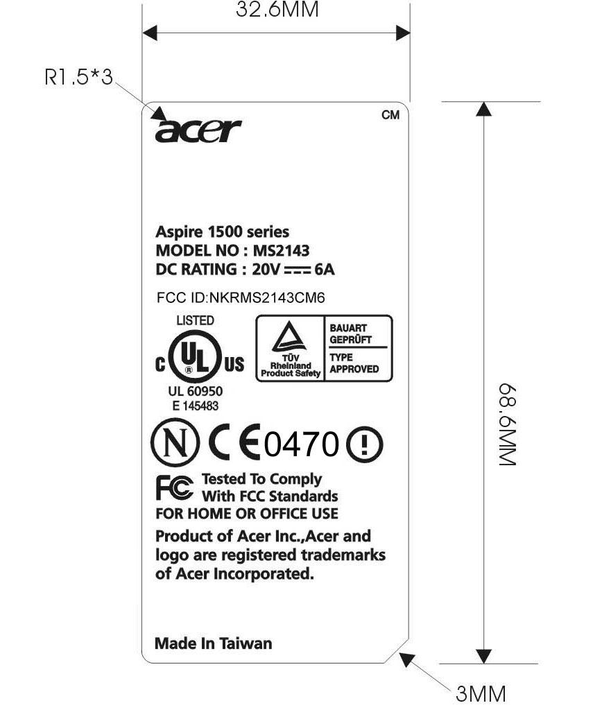
FCC Label Label Location Label Location
Internal Photos
EUT-1 EUT-2 EUT-3 EUT-4 EUT-5
Internal Photos
EUT-1 EUT-2 EUT-3 EUT-4 EUT-5
RF Exposure Info
Wistron NeWeb Corporation Release Date: 2003/11/3 Document Revision: 1 Customer Name Wistron Corporation Customer P/N 25.90137.011 / 25.90138.011 WNC P/N 25.90137.011 / 25.90138.011 Description Triple-band antenna for Gannet Provided By Wistron NeWeb Corp Reviewed By Wistron NeWeb Corp Sophia Lin Eric Fang Wistron NeWeb Corporation Release Date: 2003/11/3 1. Antenna Model Number Model number: EBO-A 2. Manufacturing Information Wistron NeWeb Corporation No. 10-1,Li-hsin Road I, Science-base Industrial Park, Hsinchu 300,Taiwan, R.O.C. 3. Antenna Configuration Aux Antenna Main Antenna Position Left-side Right-side Antenna Type PIFA PIFA Material 1. Stamped metal 2. Junkosha cable and IPEX connector 3. Sponge 4. FR4 board 1. Stamped metal 2. Junkosha cable and IPEX connector 3. Sponge 4. FR4 board Cable Length #1 1.13 (dia.) x 150 mm (white) 1.13 (dia.) x 190 mm (black) #1: Cable length is measured from the center of connector to the end of cable. 4. Antenna Photos Aux Antenna Main Antenna Wistron NeWeb Corporation Release Date: 2003/11/3 5. Antenna Dimensions (Mechanical drawings) Main antenna (Right antenna) AUX antenna (Left antenna) Wistron NeWeb Corporation Release Date: 2003/11/3 6. Antenna Gain AUX (left) Antenna Main (right) Antenna Frequency Max value Average Frequency Max value Average 2400(MHz) -1.40 dB -4.30 dB 2400(MHz) 1.29 dB -3.56 dB 2450(MHz) -0.78 dB -4.19 dB 2450(MHz) 1.97 dB -3.32 dB 2500(MHz) -0.77 dB -4.44 dB 2500(MHz) 2.89 dB -3.44 dB 5150(MHz) 3.05 dB -3.23 dB 5150(MHz) 3.68 dB -3.26 dB 5250(MHz) 2.95 dB -3.40 dB 5250(MHz) 4.00 dB -2.91 dB 5350(MHz) 2.39 dB -3.43 dB 5350(MHz) 4.82 dB -2.85 dB 5470(MHz) 1.51 dB -4.11 dB 5470(MHz) 3.56 dB -3.50 dB 5647.5(MHz) 3.38 dB -4.50 dB 5647.5(MHz) 2.47 dB -3.90 dB 5825(MHz) 2.66 dB -4.46 dB 5825(MHz) 1.25 dB -3.69 dB 7. Cable Loss (including connector) Unit: dBm 2G4 band U-NII band HyperLAN band 190 mm (Main) -0.87 -1.36 -1.40 150 mm (Aux) -0.74 -1.18 -1.21 8. Connector Info (general description) Description (Cable) Inner Conductor: AWG#32(7/0.8), Silver plating annealed copper wire Dielectric core: D0.68mm Outer conductor: 16/4/0.05 D0.93mm, Silver plating annealed copper wire Jacket: D1.13mm Requi…
Text truncated - open the document above for the full version.
Contact Information
Applicant
William Su(Senior Director / System Engineering dept.)
Technical Contact
International Standards LaboratoryJammy Chen
[email protected]886-2-86911994
No. 65, Ku Dai keng St. · Hsichih, Taipei · Taiwan
Non-Technical Contact
International Standards LaboratoryDaphne Liu
[email protected]886-2-26462550
Test Firm
International Standards LaboratoryGrace Lai
Technical Specifications
| # | Rule Parts | Frequency Range | Power Output |
|---|---|---|---|
| 1 | 15E | 5.18 GHz - 5.80 GHz | 113.76 mW |
Other Applications from Wistron NeWeb Corporation
NKR-ATTCGW453
Aug 25, 2026Enterprise product
Equipment Class
NII - Unlicensed National Information Infrastructure TXNKR-LS06B
Aug 24, 2026Touchscreen
Equipment Class
NII - Unlicensed National Information Infrastructure TXNKR-DWSZW
Aug 10, 2026Door/Window Sensor
Equipment Class
DXX - Part 15 Low Power Communication Device TransmitterNKR-TELE2
Jun 26, 2026TELE2
Equipment Class
NII - Unlicensed National Information Infrastructure TXNKR-VMC-SA525MAX
Jun 05, 2026NAD (Network Access Device)
Equipment Class
CXX - Communications Rcvr for use w/ licensed Tx and CBs