NKRRM1Mini-PCI Card
Wistron NeWeb Corporation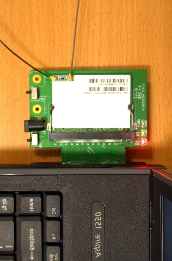
Click to zoom
Application Details
- Equipment Class
- DTS - Digital Transmission System
- Date of Grant
- Jun 29, 2004
- Application Purpose
- Original Equipment
- Date of Application
- Jun 29, 2004
- Equipment Note
- Mini-PCI Card
- Frequency Range
- 2412.00000000 - 2462.00000000
- Company
- Wistron NeWeb Corporation
- Country
- Taiwan
Documents & Files
Document Text
Text extracted from the exhibit documents filed with the FCC. Open a document above to read the original.
Users Manual
WLAN b+g mini-PCI Module RM1 OEM Installation Manual (The module is sold only to the OEM integrators & the manual is valid only for the OEM manufactures) Version: 1.0 June 2004 1 Copyright Statement No part of this publication may be reproduced, stored in a retrieval system, or transmitted in any form or by any means, whether electronic, mechanical, photocopying, recording or otherwise without the prior writing of the publisher. Windows ™ 98SE/2000/ME/XP are trademarks of Microsoft ® Corp. Pentium is trademark of Intel. All copyright reserved. 2 Federal Communication Commission Interference Statement This equipment has been tested and found to comply with the limits for a Class B digital device, pursuant to Part 15 of the FCC Rules. These limits are designed to provide reasonable protection against harmful interference in a residential installation. This equipment generates, uses and can radiate radio frequency energy and, if not installed and used in accordance with the instructions, may cause harmful interference to radio communications. However, there is no guarantee that interference will not occur in a particular installation. If this equipment does cause harmful interference to radio or television reception, which can be determined by turning the equipment off and on, the user is encouraged to try to correct the interference by one of the following measures: - Reorient or relocate the receiving antenna. - Increase the separation between the equipment and receiver. - Connect the equipment into an outlet on a circuit different from that to which the receiver is connected. - Consult the dealer or an experienced radio/TV technician for help. FCC Caution: To assure continued compliance, (example - use only shielded interface cables when connecting to computer or peripheral devices) any changes or modifications not expressly approved by the party responsible for compliance could void the user's authority to operate this equipment. This device complies with Part 15 of the FCC Rules. Operation is subject to the following two conditions: (1) This device may not cause harmful interference, and (2) This device must accept any interference received, including interference that may cause undesired operation. IMPORTANT NOTE: This module is restricted to mobile configuration. To comply with FCC RF exposure compliance requirements, the antenna used for this transmitter must be installed to provide a separation distance of at least 20 cm from all persons and must not be co-located or operating in conjunction with any other antenna or transmitter. This transmitter module must not be co-located or operating in conjunction with any other antenna or transmitter 3 Table of Contents Table of Contents.................................3 1. Introduction.....................................4 1.1 The WLAN 802.11b+g mini-PCI Module 4 1.2 Hardware Installation & Antenna Information 4 *Caution !!...........................................6 (1). This module cannot be bound in a tablet computer for RF exposure issues. (See label 1)6 (3). This module must be labeled with FCC ID. (See label 2) 6 (4). If the FCC ID is not visible when the module is installed inside another device, then the outside of device must also display a label referring to the enclosed module. The exterior label can be “ Contains Transmitter Module FCC ID:NKRRM1 ” or similar wording. (See label 3) 7 2. Features..........................................8 3. Hardware Connections.......................9 4. Remove the Module.........................11 5. Basic Configuration of your Access Point12 5.1 Logging On..............................13 5.2 Setup Wizard............................13 l 5.2.1 SETTING UP LOCAL TIME ZONE AND DATE/TIME 13 l 5.2.2 DEVICE IP SETTINGS13 l 5.2.2 DEVICE IP SETTINGS14 l 5.2.3 CONFIGURE YOUR WIRELESS LAN CONNECTION 15 l 5.2.4 FINISH SETUP WIZARD AND SAVE YOUR SETTINGS 16 4 1. Introduction 1.1 The WLAN 802.11b+g mini-PCI Module Thank you for purchasing the WLAN b+g mini-PCI Module that provides the easiest way to wireless networking. This User Manual contains detailed instructions in the operation of this product. Please keep this manual for future reference. SYSTEM REQUIREMENTS l Microsoft ® Win ™ 2000/ME/98 Second Edition/XP 1.2 Hardware Installation & Antenna Information l MODULE IS INSTALLED IN THE ROUTER. (SEE THE FOLLOWING DIAGRAMS). 5 l Antennas are embedded in the two sides (see the two antennas shown below) Only the antenna type listed below can be used: (1) Vendor WanShih Electronic CO. Model: Wss002 Important Note: This module is restricted to mobile configuration. The antennas of module should be installed and operated with minimum distance 20cm between the radiator and all persons. This transmitter must not be co-located or operating in conjunction with any other antenna or transmitter. The module is for OEM installation only and can not be sold to end user directly. Main Aux 6 *Caution !! (1). This module cannot be bound in a tablet computer for RF exposure issues. (See label 1) (3). This module must be labeled with FCC ID. (See label 2) Label 2 Label 1 7 (4). If the FCC ID is not visible when the module is installed inside another device, then the outside of device must also display a label referring to the enclosed module. The exterior label can be “ Contains Transmitter Module FCC ID:NKRRM1 ” or similar wording. (See label 3) Please put Label 3 to the enclosure of end product to note the end user. Label 3 8 2. Features n Easy integration into OEM devices n Wireless connects more PCs for Home & Office n Supports up to 128-bit WEP, WPA, AES and CCX n Cost effective solution 9 3. Hardware Connections 1. Have your Access Point Prototyping Board ready. 2. Find the mini-PCI slot on the Prototyping Board. 10 3. Insert the WLAN 802.11g mini-PCI Module into the mini-PCI slot on the Prototyping Board. 4. Press down the Module until it is secured with the two latches on the Board. 5. Hardware Installation is complete…
Text truncated - open the document above for the full version.
Cover Letter(s)
Wistron Neweb Corporation No. 10-1, Li-hsin Road 1, Science-based Industrial Park,Hsinchu 300, Taiwan, R. O. C. 886-3-666-7799 886-3-666-1654 Rev 2 C:\tmp\04LR024 RM1\FCC\attestation -letter.doc 02/08/02 Date: June.22, 2004 American Telecommunications Certification Body, Inc. 6731 Whittier Avenue Suite C110 McLean, VA 22101 FCC ID: NKRRM1 Model: RM1 Brand: Wistron NeWeb Dear Sir, We would like to declare that our product: 802.11b+g mini-PCI transmitter module, Model: RM1, FCC ID: NKRRM1 meets the requirements as a modular device which was indicated in FCC Public DA 00-1407, and to have your authorization as a modular approval. The statement is listed below: 1. “The modular transmitter must have its own RF shielding.” The radio portion of this module has been shielded, please see the attached photo “Shielding & Regulator”. 2. “The modular transmitter must have buffered modulation/data inputs.” The EUT has buffered data inputs, it is integrated in chip RT2560F.(Please see the schematic file) 3. “The modular transmitter must have its own power supply regulation.” The modulator of the transmitter needs 2.9V DC and 2.7V DC power supply for RF transmitting level. The mini-PCI interface provides 3.3V DC power supply, so there is a 3.3/2.9 DC regulator on the module, and the part number of this regulator is AME8801NEEV-2.9V (U1). Another 2.9/2.7 DC regulator on the module is AME8801HEEV-2.7V (U2). Please see the attached photo “Shielding & Regulator”. 4. “The modular transmitter must comply with the antenna requirements of section 15.203 and 15.204(c).” The EUT meets the FCC antenna requirements. The spurious emission, unique antenna connector and photos of antennas are showed in the test report. 5. “The modular transmitter must be tested in a stand-alone configuration”. The EUT is tested in a stand-alone configuration via a PCI extender board. The EUT is outside the notebook PC chassis using the extender board to extend the EUT outside the computer chassis. Please see the photo “extender board”. Wistron Neweb Corporation No. 10-1, Li-hsin Road 1, Science-based Industrial Park,Hsinchu 300, Taiwan, R. O. C. 886-3-666-7799 886-3-666-1654 Rev 2 C:\tmp\04LR024 RM1\FCC\attestation -letter.doc 02/08/02 6. “The modular transmitter must be labeled with its own FCC ID number, and, if the FCC ID is not visible when the module is installed inside another device, then the outside of the device into which the module is installed must also display a label referring to the enclosed module.” Please see exhibition label samples “Label NKRRM1” & “Label Exterior”. And also in the OEM installation manual, there are labels and the instructions on how to label the end product. 7. “The modular transmitter must comply with any specific rule or operating requirements applicable to the transmitter and the manufacturer must provide adequate instructions along with the module to explain any such requirement.” The EUT is compliant with all applicable FCC rules. Detail instructions for maintaining compliance are given in the manual. 8. “The modular transmitter must comply with any applicable RF exposure requirements.” The EUT is compliant with the applicable RF exposure requirements. RF Exposure is addressed in the MPE test report. This request for modular approval is restricted to applications in mobile Host configurations only. Thanks for your help and do not hesitate to contact us if you have any further questions. Yours sincerely, ________________ Mr. Edward Yeh / Engineer Wistron NeWeb Corporation Wistron Neweb Corporation No. 10-1, Li-hsin Road 1, Science-based Industrial Park,Hsinchu 300, Taiwan, R. O. C. 886-3-666-7799 886-3-666-1654 Rev 2 C:\tmp\04LR024 RM1\FCC\attestation -letter.doc 02/08/02 “ Shielding & Regulator” Shielding 3.3V/2.9V Regulator 2.9V/2.7V Regulator Wistron Neweb Corporation No. 10-1, Li-hsin Road 1, Science-based Industrial Park,Hsinchu 300, Taiwan, R. O. C. 886-3-666-7799 886-3-666-1654 Rev 2 C:\tmp\04LR024 RM1\FCC\attestation -letter.doc 02/08/02 Extender board Wistron Neweb Corporation No. 10-1, Li-hsin Road 1, Science-based Industrial Park,Hsinchu 300, Taiwan, R. O. C. 886-3-666-7799 886-3-666-1654 Rev 2 C:\tmp\04LR024 RM1\FCC\attestation -letter.doc 02/08/02 RM1 label For sytem label
Cover Letter(s)
Wistron Neweb Corporation No. 10-1, Li-hsin Road 1, Science-based Industrial Park,Hsinchu 300, Taiwan, R. O. C. 886-3-666-7799 886-3-666-1654 Rev 2 C:\tmp\04LR024 RM1\FCC\AP FORM.doc 02/08/02 Letter Of Agency Date: Jun. 25, 2004 American Telecommunications Certification Body, Inc. 6731 Whittier Avenue Suite C110 McLean, VA 22101 To Whom It May Concern: Please be advised that Wistron NeWeb Corporation authorizes International Standards Laboratory (ISL) to act on our behalf, until otherwise notified, for applications submitted to American Telecommunications Certification Body, Inc. (ATCB). We certify that we are not subject to denial of federal benefits that includes FCC benefits, pursuant to Section 5301 of the Anti-Drug Abuse ACT of 1988, U.S.C. 862. Further, no party as defined in 47 CFR 1.2002(b), for this application is subject to denial of federal benefits that includes FCC benefits. Thank you for your attention to this matter. ________________ Mr. Edward Yeh / Engineer Wistron NeWeb Corporation Wistron Neweb Corporation No. 10-1, Li-hsin Road 1, Science-based Industrial Park,Hsinchu 300, Taiwan, R. O. C. 886-3-666-7799 886-3-666-1654 Rev 2 C:\tmp\04LR024 RM1\FCC\AP FORM.doc 02/08/02 Date: Jun. 24, 2004 American Telecommunications Certification Body, Inc. 6731 Whittier Avenue Suite C110 McLean, VA 22101 RE: Certification Application FCC ID: NKRRM1 Model: RM1 We would like to apply for FCC Certification on the subject model (EUT). The EUT is a WLAN 802.11g miniPCI module. We have uploaded the related document for the EUT onto your website. Please review the information we submitted and issue us a grant for the subject model. If you have any comments, please do not hesitate to contact us. Thank you for your attention to these matters. Sincerely, ________________ Mr. Edward Yeh / Engineer Wistron NeWeb Corporation Wistron Neweb Corporation No. 10-1, Li-hsin Road 1, Science-based Industrial Park,Hsinchu 300, Taiwan, R. O. C. 886-3-666-7799 886-3-666-1654 Rev 2 C:\tmp\04LR024 RM1\FCC\AP FORM.doc 02/08/02 FCC Labeling Requirements and Information Date: Jun. 25, 2004 American Telecommunications Certification Body, Inc. 6731 Whittier Avenue Suite C110 McLean, VA 22101 RE: Certification Application FCC ID: NKRRM1 Model: RM1 The following label information is required by the FCC Rules and Regulations for certified devices. Please find marketing information required by the FCC Rules and Regulations as following: Label Requirements An intentional radiator device subject to certification by the FCC shall carry a warning label which includes the following statement: This device complies with Part 15 of the FCC Rules. Operation is subject to the following two conditions: (1) this device may not cause harmful interference, and (2) this device must accept any interference received, including interference that may cause undesired operation. The sample label shown shall be permanently affixed at a conspicuous location on the device and be readily visible to the user at the time of purchase. Sincerely, ________________ Mr. Edward Yeh / Engineer Wistron NeWeb Corporation FCC ID: NKRRM1 This device complies with Part 15 of the FCC Rules. Operation is subject to the following two conditions: (1) This device may not cause harmful interference, and (2) this device must accept any interference received, including interference that may cause undesired operation. Wistron Neweb Corporation No. 10-1, Li-hsin Road 1, Science-based Industrial Park,Hsinchu 300, Taiwan, R. O. C. 886-3-666-7799 886-3-666-1654 Rev 2 C:\tmp\04LR024 RM1\FCC\AP FORM.doc 02/08/02 Request for Confidentiality Date: Jun. 24, 2004 American Telecommunications Certification Body, Inc. 6731 Whittier Avenue Suite C110 McLean, VA 22101 RE: Certification Application FCC ID: NKRRM1 Model: RM1 Please be advised that the following information is to be held confidential on behalf of Wistron NeWeb Corporation : q Block Diagram q Schematics q Technical Spec The application contains technical information which Wistron NeWeb Corporation deems to be trade secrets and proprietary. If made public, the information might be used to the disadvantage of the applicant in the market place. Thank you for your attention to this matter. Sincerely, ________________ Mr. Edward Yeh / Engineer Wistron NeWeb Corporation Wistron Neweb Corporation No. 10-1, Li-hsin Road 1, Science-based Industrial Park,Hsinchu 300, Taiwan, R. O. C. 886-3-666-7799 886-3-666-1654 Rev 2 C:\tmp\04LR024 RM1\FCC\AP FORM.doc 02/08/02
External Photos
International Standards Laboratory Report Number: ISL-04LR024P HC LAB:NVLAP:200234-0;VCCI: R-341,C-354;NEMKO:ELA 113a,113c;BSMI:SL2-IN-E-0037;SL2-R1-E-0037;CNLA:1178 LT LAB:NVLAP:200234-0;VCCI: R-1435,C-1440;NEMKO:ELA 113b,113d;BSMI:SL2-IN-E-0013;CNLA:0997 -4- EUT-4 International Standards Laboratory Report Number: ISL-04LR024P HC LAB:NVLAP:200234-0;VCCI: R-341,C-354;NEMKO:ELA 113a,113c;BSMI:SL2-IN-E-0037;SL2-R1-E-0037;CNLA:1178 LT LAB:NVLAP:200234-0;VCCI: R-1435,C-1440;NEMKO:ELA 113b,113d;BSMI:SL2-IN-E-0013;CNLA:0997 -5- EUT-5
ID Label/Location Info
Label This device complies with Part 15 of the FCC Rules. Operation is subject to the following two conditions: (1) This device may not cause harmful interference, and (2) this device must accept any interference received, including interference that may cause undesired operation. Label & Location Warning statement Rating Label
Internal Photos
International Standards Laboratory Report Number: ISL-04LR024P HC LAB:NVLAP:200234-0;VCCI: R-341,C-354;NEMKO:ELA 113a,113c;BSMI:SL2-IN-E-0037;SL2-R1-E-0037;CNLA:1178 LT LAB:NVLAP:200234-0;VCCI: R-1435,C-1440;NEMKO:ELA 113b,113d;BSMI:SL2-IN-E-0013;CNLA:0997 -1- EUT-1 International Standards Laboratory Report Number: ISL-04LR024P HC LAB:NVLAP:200234-0;VCCI: R-341,C-354;NEMKO:ELA 113a,113c;BSMI:SL2-IN-E-0037;SL2-R1-E-0037;CNLA:1178 LT LAB:NVLAP:200234-0;VCCI: R-1435,C-1440;NEMKO:ELA 113b,113d;BSMI:SL2-IN-E-0013;CNLA:0997 -2- EUT-2 International Standards Laboratory Report Number: ISL-04LR024P HC LAB:NVLAP:200234-0;VCCI: R-341,C-354;NEMKO:ELA 113a,113c;BSMI:SL2-IN-E-0037;SL2-R1-E-0037;CNLA:1178 LT LAB:NVLAP:200234-0;VCCI: R-1435,C-1440;NEMKO:ELA 113b,113d;BSMI:SL2-IN-E-0013;CNLA:0997 -3- EUT-3
Operational Description
Operational Description For WLAN b+g Mini-PCI Module Model: RM1 The WLAN 802.11b+g Mini-PCI Module is embedded 2.4GHz Wireless Local Area Network Mini-PCI adapter. The channel and the frequency are located on the free licensed ISM band from 2400MHz to 2483.5MHz (11b/11g), and different Modulations are applied to different select data rate mechanism. For being in 802.11b mechanism, the DBPSK modulation operates at 1Mbps low date transmit rate, the DQPSK modulation operates at 2Mbps standard date transmit rate, the CCK operates at 5.5 medium and 11Mbps high date transmit rate respectively. For being in 802.11g mechanism, the BPSK-OFDM modulation operates at 6Mbps/9Mbps date transmit rate, the QPSK-OFDM modulation operates at 12Mbps/18Mbps date transmit rate, the 16QUAM-OFDM operates at 24Mbps/36Mbps date transmit rate, the 64QUAM-OFDM operates at 48Mbps/54Mbps date transmit rate respectively. There are 11 operation channels in 802.11b & 802.11g. The adapter is 60mm x 45mm in dimension, and mainly contains a 196- pin MAC controller and a fully duplex RF transceiver module inside. The transceiver module contains a 49-pin 802.11b/g modulator , and a 16-pin Power Amplifiers. The RF transceiver is connected to a set of antennas via its transmit and receive Hirose connectors. For reducing the fading effect, the antenna diversity is applied. The distance between the main antenna and the aux antenna should be kept a half of the wave length. The Mini-PCI form factor is designed for router where overall thickness must be kept to an absolute minimum. When the PCI interface connects the WLAN adapter and router for baseband data communicating, the adapter could be bound inside the router, and a high frequency coaxial cable along the casing links the adapter and the antenna. The distance among the antenna, the adapter, and the human body would be large enough for anti-interference and anti-exposure in normal operation.
RF Exposure Info
Report Number: 04LR024MPE Issue Date: 2004/06/18 HC LAB:NVLAP:200234-0;VCCI: R-341,C-354;NEMKO:ELA 113a,113c;BSMI:SL2-IN-E-0037;SL2-R1-E-0037;CNLA:1178 LT LAB:NVLAP:200234-0;VCCI: R-1435,C-1440;NEMKO:ELA 113b,113d;BSMI:SL2-IN-E-0013;CNLA:0997 MPE Test Report of Product Name FCC Part 15 Subpart B & C & E of WLAN b+g mini-PCI Module Model RM1 (Brand: Wistron NeWeb) Applied by: Wistron Neweb Corporation No. 10-1, Li-hsin Road 1, Science-based Indus Taiwan, R. O. C. Test Performed by: International Standards Laboratory No. 120, Lane 180, San Ho Tsuen, Hsin Ho Rd. Lung-Tan Hsiang, Tao Yuan County 325 Taiwan, R.O.C. Tel:(03)407-1718 Fax:(03)407-1738 International Standards Laboratory Report Number: 04LR018MPE HC LAB:NVLAP:200234-0;VCCI: R-341,C-354;NEMKO:ELA 113a,113c;BSMI:SL2-IN-E-0037;SL2-R1-E-0037;CNLA:1178 LT LAB:NVLAP:200234-0;VCCI: R-1435,C-1440;NEMKO:ELA 113b,113d;BSMI:SL2-IN-E-0013;CNLA:0997 Contents of Report 1. General...............................................................................................1 1.1 Certification of Accuracy of Test Data......................................................................1 2. Description of Equipment Under Test (EUT)................................2 2.1 General Test Conditions.............................................................................................3 3. RF Exposure Measurement [Section 15.247(b)(4) & 1.1307(b)]..............4 3.1 Applied Standards......................................................................................................4 3.2 Test Procedure............................................................................................................4 3.3 Test Setup...................................................................................................................4 3.4 Calculation for Maximum Permissible Exposure (MPE)..........................................4 4. Appendix : Test Equipment...................................................................6 4.1 Test Equipment List...................................................................................................6 FCC ID:NKRRM1 International Standards Laboratory Report Number: 04LR024MPE HC LAB:NVLAP:200234-0;VCCI: R-341,C-354;NEMKO:ELA 113a,113c;BSMI:SL2-IN-E-0037;SL2-R1-E-0037;CNLA:1178 LT LAB:NVLAP:200234-0;VCCI: R-1435,C-1440;NEMKO:ELA 113b,113d;BSMI:SL2-IN-E-0013;CNLA:0997 -1- 1. General 1.1 Certification of Accuracy of Test Data Standards: CFR 47 Part 15 Subpart B Class B CFR 47 Part 15 Subpart C (Section 15.247) Test Procedure: ANSI C63.4: 2001 Equipment Tested: WLAN b+g mini-PCI Module Model: RM1 Applied by: Wistron Neweb Corporation Sample received Date: 2004/06/10 Final test Date : 2004/06/18 Test Site: Chamber 02, Conduction 02 Temperature Refer to each site test data Humidity: Refer to each site test data Test Engineer: Jerry Chiou All the tests in this report have been performed and recorded in accordance with the standards described above and performed by an independent electromagnetic compatibility consultant, International Standards Laboratory. The test results contained in this report accurately represent the the measurements of the characteristics and the energy generated by sample equipment under test at the time of the test. The sample equipment tested as described in this report is in compliance with the limits of above standards. Approve & Signature --------------------------------------- Eddy Hsiung/Director Test results given in this report apply only to the specific sample(s) tested under stated test conditions. This report shall not be reproduced other than in full without the explicit written consent of ISL. This report totally 8 pages, including 1 cover page , 1 contents page, and 6 pages for the test description. This report must not be use to claim product endorsement by NVLAP or any agency of the U.S. Government. This test data shown below is traceable to NIST or national or international standard. International Standards Laboratory certifies that no party to this application has been denied the FCC benefits pursuant to Section 5301 of the Anti-Drug Abuse Act of 1988, 21 U.S.C. 853(a). FCC ID:NKRRM1 International Standards Laboratory Report Number: 04LR024MPE HC LAB:NVLAP:200234-0;VCCI: R-341,C-354;NEMKO:ELA 113a,113c;BSMI:SL2-IN-E-0037;SL2-R1-E-0037;CNLA:1178 LT LAB:NVLAP:200234-0;VCCI: R-1435,C-1440;NEMKO:ELA 113b,113d;BSMI:SL2-IN-E-0013;CNLA:0997 -2- 2. Description of Equipment Under Test (EUT) Description: WLAN 802.11g miniPCI Module Model No.: RM1 FCC ID: NKRRM1 Brand: Wistron NeWeb Frequency Range 802.11b/g: 2400~2483.5 MHz Support channel: 802.11b/g 11 Channels Modulation Skill: 802.11b DBPSK(1Mbps), DQPSK(2Mbps), CCK(5.5/11Mbps) 802.11g OFDM (6M - 54Mbps) Antennas Type: Monopole ,reverse SMA (Model: Wss002, WanShih Electronic CO. Antenna Connected: The antenna is connected to the RF connector of the WLAN adapter. Antenna peak Gain: 2.31 dBi (11b/g) WLAN Power Type : 3.3V DC from the EUT The channel and the operation frequency of 802.11b and 802.11g is listed below: Channel Frequency(MHz) Channel Frequency(MHz) 01 2412 07 2442 02 2417 08 2447 03 2422 09 2452 04 2427 10 2457 05 2432 11 2462 06 2437 During the test, the EUT was tested as a modular device of a notebook PC using a PCMCIA extender board to extend the EUT outside the notebook PC enclosure. FCC ID:NKRRM1 International Standards Laboratory Report Number: 04LR024MPE HC LAB:NVLAP:200234-0;VCCI: R-341,C-354;NEMKO:ELA 113a,113c;BSMI:SL2-IN-E-0037;SL2-R1-E-0037;CNLA:1178 LT LAB:NVLAP:200234-0;VCCI: R-1435,C-1440;NEMKO:ELA 113b,113d;BSMI:SL2-IN-E-0013;CNLA:0997 -3- 2.1 General Test Conditions 1. During the test, the EUT was set in continuously transmitting mode with a duty cycle of 100%. 2. The channel 1, 6, 11 of of 802.11b/g of EUT were all tested. FCC ID:NKRRM1 International Standards Laboratory Report Number: 04LR024MPE HC LAB:NVLAP:200234-0;VCCI: R-341,C-354;NEMKO:ELA 113a,113c;BSMI:SL2-IN-E-0037;SL2-R1-E-0037;CNLA:1…
Text truncated - open the document above for the full version.
Test Report
Report Number: ISL-04LR024FC Issue Date: 2004/06/10 HC LAB:NVLAP:200234-0;VCCI: R-341,C-354;NEMKO:ELA 113a,113c;BSMI:SL2-IN-E-0037;SL2-R1-E-0037;CNLA:1178 LT LAB:NVLAP:200234-0;VCCI: R-1435,C-1440;NEMKO:ELA 113b,113d;BSMI:SL2-IN-E-0013;CNLA:0997 ISL-T10-R29-1 Test Report for FCC Part 15 Subpart B & C of WLAN 802.11g miniPCI module Model RM1 (Brand: Wistron NeWeb) Applied by: Wistron Neweb Corporation No. 10-1, Li-hsin Road 1, Science-based Indus Taiwan, R. O. C. Test Performed by: International Standards Laboratory No. 120, Lane 180, San Ho Tsuen, Hsin Ho Rd. Lung-Tan Hsiang, Tao Yuan County 325 Taiwan, R.O.C. Tel:(03)407-1718 Fax:(03)407-1738 FCC ID:NKRRM1 International Standards Laboratory Report Number: 04LR024FC HC LAB:NVLAP:200234-0;VCCI: R-341,C-354;NEMKO:ELA 113a,113c;BSMI:SL2-IN-E-0037;SL2-R1-E-0037;CNLA:1178 LT LAB:NVLAP:200234-0;VCCI: R-1435,C-1440;NEMKO:ELA 113b,113d;BSMI:SL2-IN-E-0013;CNLA:0997 -i- Contents of Report 1. General..............................................................................................................................1 1.1 Certification of Accuracy of Test Data.............................................................................1 2. Test Results Summary........................................................................................................2 3. Description of Equipment Under Test (EUT).......................................................................3 4. TEST RESULTS (802.11b)...............................................................................................4 4.1 Powerline Conducted Emissions [Section 15.207]...........................................................4 4.1.1 EUT Configuration...................................................................................................4 4.1.2 Test Procedure........................................................................................................4 4.1.3 EMI Receiver/Spectrum Analyzer Configuration (for the frequencies tested)..............4 4.1.4 Test Data:................................................................................................................5 4.2 Bandwidth for DSSS [Section 15.247 (a)(2)]..................................................................7 4.2.1 Test Procedure........................................................................................................7 4.2.2 Test Setup...............................................................................................................7 4.2.3 Test Data:................................................................................................................7 4.3 DSSS Maximum Peak Output Power [Section 15.247 (b)(1)].......................................10 4.3.1 Test Procedure......................................................................................................10 4.3.2 Test Setup.............................................................................................................10 4.3.3 Test Data...............................................................................................................10 4.4 Radiated Emission Measurement [Section [15.247(c)(4)]..............................................11 4.4.1 EUT Configuration.................................................................................................11 4.4.2 Test Procedure......................................................................................................11 4.4.3 EMI Receiver/Spectrum Analyzer Configuration (for the frequencies tested)............11 4.4.4 Test Data (30MHz – 1GHz):..................................................................................12 4.4.5 Test Data ( 1GHz – 25 GHz) ................................................................................13 4.5 Band Edge Measurement..............................................................................................16 4.5.1 Test Procedure (Conducted)..................................................................................16 4.5.2 Test Setup (Conducted).........................................................................................16 4.5.3 Test Data:..............................................................................................................16 4.5.4 Test Procedure (Radiated).....................................................................................18 4.5.5 Test Setup (Radiated)............................................................................................18 4.5.6 Test Data...............................................................................................................19 4.6 RF Exposure Measurement [Section 15.247(b)(4) & 1.1307(b)]...................................22 4.7 DSSS Peak Power Spectral Density [Section 15.247(d) ].............................................23 4.7.1 Test Procedure......................................................................................................23 4.7.2 Test Setup.............................................................................................................23 4.7.3 Test Data...............................................................................................................23 FCC ID:NKRRM1 International Standards Laboratory Report Number: 04LR024FC HC LAB:NVLAP:200234-0;VCCI: R-341,C-354;NEMKO:ELA 113a,113c;BSMI:SL2-IN-E-0037;SL2-R1-E-0037;CNLA:1178 LT LAB:NVLAP:200234-0;VCCI: R-1435,C-1440;NEMKO:ELA 113b,113d;BSMI:SL2-IN-E-0013;CNLA:0997 -ii- 5. TEST RESULTS (802.11g)................................................................................…
Text truncated - open the document above for the full version.
Contact Information
Applicant
William Su(Senior Director / System Engineering dept.)
Technical Contact
International Standards LaboratoryJames Cheng
[email protected]886-3-407-1718
No. 65, Ku Dai Keng Street · Hsichih · Taiwan
Non-Technical Contact
International Standards LaboratoryDaphne Liu
[email protected]886-2-2646-2550
Test Firm
International Standards LaboratoryDavid Wu
Technical Specifications
| # | Rule Parts | Frequency Range | Power Output |
|---|---|---|---|
| 1 | 15C | 2.41 GHz - 2.46 GHz | 80.11 mW |
Other Applications from Wistron NeWeb Corporation
NKR-ATTCGW453
Aug 25, 2026Enterprise product
Equipment Class
NII - Unlicensed National Information Infrastructure TXNKR-LS06B
Aug 24, 2026Touchscreen
Equipment Class
NII - Unlicensed National Information Infrastructure TXNKR-DWSZW
Aug 10, 2026Door/Window Sensor
Equipment Class
DXX - Part 15 Low Power Communication Device TransmitterNKR-TELE2
Jun 26, 2026TELE2
Equipment Class
NII - Unlicensed National Information Infrastructure TXNKR-VMC-SA525MAX
Jun 05, 2026NAD (Network Access Device)
Equipment Class
CXX - Communications Rcvr for use w/ licensed Tx and CBs