NKRRM8802.11g mini-PCI Module
Wistron NeWeb Corporation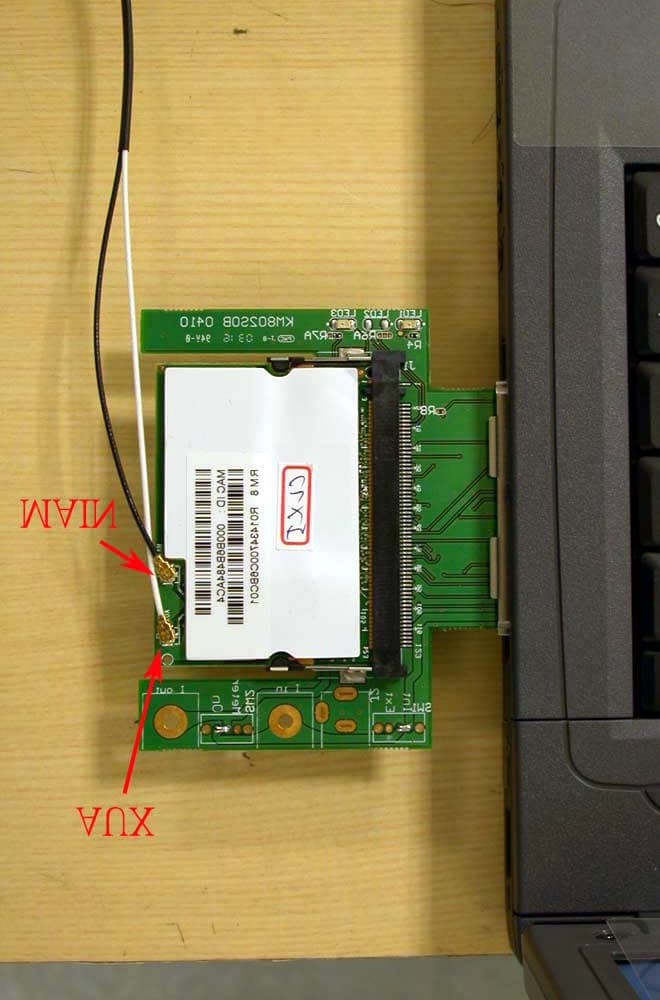
Click to zoom
Application Details
- Equipment Class
- DTS - Digital Transmission System
- Date of Grant
- Dec 23, 2003
- Application Purpose
- Original Equipment
- Date of Application
- Dec 23, 2003
- Equipment Note
- 802.11g mini-PCI Module
- Frequency Range
- 2412.00000000 - 2462.00000000
- Company
- Wistron NeWeb Corporation
- Country
- Taiwan
Documents & Files
Document Text
Text extracted from the exhibit documents filed with the FCC. Open a document above to read the original.
Users Manual
WLAN 802.11g Mini-PCI Module RM8 OEM Installation Manual (The module is sold only to the OEM integrators & the manual is valid only for the OEM manufactures) Version: 1.0 Sep. 2003 1 Copyright Statement No part of this publication may be reproduced, stored in a retrieval system, or transmitted in any form or by any means, whether electronic, mechanical, photocopying, recording or otherwise without the prior writing of the publisher. Windows ™ 98SE/2000/ME/XP are trademarks of Microsoft ® Corp. Pentium is trademark of Intel. All copyright reserved. 2 Federal Communication Commission Interference Statement This equipment has been tested and found to comply with the limits for a Class B digital device, pursuant to Part 15 of the FCC Rules. These limits are designed to provide reasonable protection against harmful interference in a residential installation. This equipment generates, uses and can radiate radio frequency energy and, if not installed and used in accordance with the instructions, may cause harmful interference to radio communications. However, there is no guarantee that interference will not occur in a particular installation. If this equipment does cause harmful interference to radio or television reception, which can be determined by turning the equipment off and on, the user is encouraged to try to correct the interference by one of the following measures: - Reorient or relocate the receiving antenna. - Increase the separation between the equipment and receiver. - Connect the equipment into an outlet on a circuit different from that to which the receiver is connected. - Consult the dealer or an experienced radio/TV technician for help. FCC Caution: To assure continued compliance, (example - use only shielded interface cables when connecting to computer or peripheral devices) any changes or modifications not expressly approved by the party responsible for compliance could void the user's authority to operate this equipment. This device complies with Part 15 of the FCC Rules. Operation is subject to the following two conditions: (1) This device may not cause harmful interference, and (2) This device must accept any interference received, including interference that may cause undesired operation. IMPORTANT NOTE: This module is restricted to mobile configuration. To comply with FCC RF exposure compliance requirements, the antenna used for this transmitter must be installed to provide a separation distance of at least 20 cm from all persons and must not be co-located or operating in conjunction with any other antenna or transmitter. This transmitter module must not be co-located or operating in conjunction with any other antenna or transmitter 3 Table of Contents 1. INTRODUCTION....................................................................................................4 1.1 THE WLAN 802.11G MINI-PCI MODULE.............................................................4 1.2 FEATURES.............................................................................................................4 1.3 HARDWARE INSTALLATION & ANTENNA INFORMATION...................4 2. PLANNING YOUR WIRELESS NETWORK.....................................................8 2.1 NETWORK TOPOLOGY...........................................................................................8 2.2 AD-HOC VERSUS INFRASTRUCTURE MODE...........................................................8 3. SOFTWARE INSTALLATION AND UNINSTALLATION..............................10 3.1 SETUP WIZARD INSTALLATION....................................................................10 3.2 ADDITIONAL SETUP PROCESSES..........................................................................12 3.3 DISABLE WINDOWS XP ZERO-CONFIGURATION.................................................14 3.4 UNINSTALLATION................................................................................................15 4. USING THE CONFIGURATION UTILITY......................................................17 4.1 OVERVIEW..........................................................................................................17 4.2 ACCESSING THE CONFIGURATION UTILITY..........................................................17 4.3 LINK STATUS.......................................................................................................21 4.4 SITE MONITOR....................................................................................................22 4.5 STATISTICS..........................................................................................................23 4.6 DIAGNOSTICS......................................................................................................24 4.7 INFORMATION......................................................................................................25 APPENDIX A: FAQ...................................................................................................26 APPENDIX B: GLOSSARY.....................................................................................29 APPENDIX C: SPECIFICATION...........................................................................34 4 1. Introduction 1.1 The WLAN 802.11g mini-PCI Module 802.11g is the 54Mbps wireless networking standard that's almost five times faster than the widely deployed 802.11b products found in homes, businesses, and public wireless hotspots around the country — but since they share the same 2.4GHz radio band, 802.11g devices can also work with existing 11Mbps 802.11b equipment. The new 802.11g mini-PCI Module has both standards built in, so you can connect your notebook to existing 802.11b infrastructure, and also the new screaming fast 802.11g networks. The included Setup Wizard will walk you through configuring the module to your network's settings, step by step. Once you're connected, you can keep in touch with your e-mail, access the Internet, and share files and other resources such as printers and network storage with other c…
Text truncated - open the document above for the full version.
Cover Letter(s)
Wistron Neweb Corporation No. 10-1, Li-hsin Road 1, Science-based Industrial Park,Hsinchu 300, Taiwan, R. O. C. 886-3-666-7799 886-3-666-1654 Rev 2 C:\tmp\03LR026 RM8 CL51\FCC\AP FORM.doc 02/08/02 Letter Of Agency Date: Dec. 10, 2003 American Telecommunications Certification Body, Inc. 6731 Whittier Avenue Suite C110 McLean, VA 22101 To Whom It May Concern: Please be advised that Wistron NeWeb Corporation authorizes International Standards Laboratory (ISL) to act on our behalf, until otherwise notified, for applications submitted to American Telecommunications Certification Body, Inc. (ATCB). We certify that we are not subject to denial of federal benefits that includes FCC benefits, pursuant to Section 5301 of the Anti-Drug Abuse ACT of 1988, U.S.C. 862. Further, no party as defined in 47 CFR 1.2002(b), for this application is subject to denial of federal benefits that includes FCC benefits. Thank you for your attention to this matter. ________________ Eric Liu / Sr. Manager Engineer Wistron NeWeb Corporation Wistron Neweb Corporation No. 10-1, Li-hsin Road 1, Science-based Industrial Park,Hsinchu 300, Taiwan, R. O. C. 886-3-666-7799 886-3-666-1654 Rev 2 C:\tmp\03LR026 RM8 CL51\FCC\AP FORM.doc 02/08/02 FCC Labeling Requirements and Information Date: Dec. 10, 2003 American Telecommunications Certification Body, Inc. 6731 Whittier Avenue Suite C110 McLean, VA 22101 RE: FCC Labeling Requirements FCC ID: NKRRM8 The following label information is required by the FCC Rules and Regulations for certified devices. Please find marketing information required by the FCC Rules and Regulations as following: Label Requirements An intentional radiator device subject to certification by the FCC shall carry a warning label which includes the following statement: (Due to space limitation, this statement has be shown on Users’ Manual Page 2.) This device complies with Part 15 of the FCC Rules. Operation is subject to the following two conditions: (1) this device may not cause harmful interference, and (2) this device must accept any interference received, including interference that may cause undesired operation. The sample label shown shall be permanently affixed at a conspicuous location on the device and be readily visible to the user at the time of purchase. FCC ID: NKRRM8 Thank you for your attention to these matters. Sincerely, ________________ Eric Liu / Sr. Manager Engineer Wistron NeWeb Corporation Wistron Neweb Corporation No. 10-1, Li-hsin Road 1, Science-based Industrial Park,Hsinchu 300, Taiwan, R. O. C. 886-3-666-7799 886-3-666-1654 Rev 2 C:\tmp\03LR026 RM8 CL51\FCC\AP FORM.doc 02/08/02 Request for Confidentiality Date: Dec. 10, 2003 American Telecommunications Certification Body, Inc. 6731 Whittier Avenue Suite C110 McLean, VA 22101 RE: Certification Application FCC ID: NKRRM8 Please be advised that the following information is to be held confidential on behalf of Wistron NeWeb Corporation : q Block Diagram q Schematics q Technical Spec The application contains technical information which Wistron NeWeb Corporation deems to be trade secrets and proprietary. If made public, the information might be used to the disadvantage of the applicant in the market place. Thank you for your attention to this matter. Sincerely, ________________ Eric Liu / Sr. Manager Engineer Wistron NeWeb Corporation
Cover Letter(s)
Wistron Neweb Corporation No. 10-1, Li-hsin Road 1, Science-based Industrial Park,Hsinchu 300, Taiwan, R. O. C. 886-3-666-7799 886-3-666-1654 Rev 2 C:\tmp\03LR026 RM8 CL51\FCC\attestation -letter.doc 02/08/02 Date: Dec.10, 2003 American Telecommunications Certification Body, Inc. 6731 Whittier Avenue Suite C110 McLean, VA 22101 FCC ID: NKRRM8 Model: RM8 Brand: Wistron NeWeb Dear Sir, We would like to declare that our product: 802.11g mini-PCI transmitter module, Model: RM8, FCC ID: NKRRM8 meets the requirements as a modular device which was indicated in FCC Public DA 00- 1407, and to have your authorization as a modular approval. The statement is listed below: 1. “The modular transmitter must have its own RF shielding” The radio portion of this module has been shielded, please see the attached photo “Shielding”. 2. “The modular transmitter must have buffered modulation/data inputs.” The EUT has buffered data inputs, it is integrated in chip BCM4306KFB.(Please see the schematic file) 3. “The modular transmitter must have its own power supply regulation.” The transmitter is a homodyne structure, and the baseband / rf modulator needs 3.0 V DC power supply. The mini- PCI interface provides 3.3V DC power supply, so there is a 3.3/3.0 DC regulator on the module, and the part number of this regulator is LP298518. Please see the attached photo “Regulator”. 4. “The modular transmitter must comply with the antenna requirements of section 15.203 and 15.204(c).” The EUT meets the FCC antenna requirements. The spurious emission, unique antenna connector and photos of antennas are showed in the test report. 5. “The modular transmitter must be tested in a stand-alone configuration”. The EUT is tested in a stand-alone configuration via a PCI extender board. The EUT is outside the notebook PC chassis using the extender board to extend the EUT outside the computer chassis. Please see the photo “extender board”. Wistron Neweb Corporation No. 10-1, Li-hsin Road 1, Science-based Industrial Park,Hsinchu 300, Taiwan, R. O. C. 886-3-666-7799 886-3-666-1654 Rev 2 C:\tmp\03LR026 RM8 CL51\FCC\attestation -letter.doc 02/08/02 6. “The modular transmitter must be labeled with its own FCC ID number, and, if the FCC ID is not visible when the module is installed inside another device, then the outside of the device into which the module is installed must also display a label referring to the enclosed module.” Please see exhibition label samples “Label RM8” & “Label Exterior”. And also in the OEM installation manual, there are labels and the instructions on how to label the end product. 7. “The modular transmitter must comply with any specific rule or operating requirements applicable to the transmitter and the manufacturer must provide adequate instructions along with the module to explain any such requirement.” The EUT is compliant with all applicable FCC rules. Detail instructions for maintaining compliance are given in the manual. 8. “The modular transmitter must comply with any applicable RF exposure requirements.” The EUT is compliant with the applicable RF exposure requirements. RF Exposure is addressed in the section 4.6 & 5.6 (MPE) of the test report. This request for modular approval is restricted to applications in mobile Host configurations only. Thanks for your help and do not hesitate to contact us if you have any further questions. Yours sincerely, Sincerely, ________________ Eric Liu / Sr. Manager Engineer Wistron NeWeb Corporation Wistron Neweb Corporation No. 10-1, Li-hsin Road 1, Science-based Industrial Park,Hsinchu 300, Taiwan, R. O. C. 886-3-666-7799 886-3-666-1654 Rev 2 C:\tmp\03LR026 RM8 CL51\FCC\attestation -letter.doc 02/08/02 “ Shielding” “ Regulator” 3.3/3.0V Regulator Wistron Neweb Corporation No. 10-1, Li-hsin Road 1, Science-based Industrial Park,Hsinchu 300, Taiwan, R. O. C. 886-3-666-7799 886-3-666-1654 Rev 2 C:\tmp\03LR026 RM8 CL51\FCC\attestation -letter.doc 02/08/02 Extender board
External Photos
International Standards Laboratory Report Number: ISL-03LR026PP NVLAP Lab. Code: 200234-0; VCCI: R-341, C-354; NEMKO Aut. No: ELA 113a; BSMI Lab. Code: SL2-IN-E-0013 International Standards Laboratory Report Number: ISL-03LR026PP NVLAP Lab. Code: 200234-0; VCCI: R-341, C-354; NEMKO Aut. No: ELA 113a; BSMI Lab. Code: SL2-IN-E-0013
ID Label/Location Info
FCC Label Label Location Label Location
Internal Photos
International Standards Laboratory Report Number: ISL-03LR026PP NVLAP Lab. Code: 200234-0; VCCI: R-341, C-354; NEMKO Aut. No: ELA 113a; BSMI Lab. Code: SL2-IN-E-0013 Appendix Photographs of EUT of WLAN 802.11g Mini-PCI Module Model RM8 (Brand: Wistron NeWeb) International Standards Laboratory Report Number: ISL-03LR026PP NVLAP Lab. Code: 200234-0; VCCI: R-341, C-354; NEMKO Aut. No: ELA 113a; BSMI Lab. Code: SL2-IN-E-0013 -1- EUT-1 International Standards Laboratory Report Number: ISL-03LR026PP NVLAP Lab. Code: 200234-0; VCCI: R-341, C-354; NEMKO Aut. No: ELA 113a; BSMI Lab. Code: SL2-IN-E-0013 -2- EUT-2 International Standards Laboratory Report Number: ISL-03LR026PP NVLAP Lab. Code: 200234-0; VCCI: R-341, C-354; NEMKO Aut. No: ELA 113a; BSMI Lab. Code: SL2-IN-E-0013 -3- EUT-3 International Standards Laboratory Report Number: ISL-03LR026PP NVLAP Lab. Code: 200234-0; VCCI: R-341, C-354; NEMKO Aut. No: ELA 113a; BSMI Lab. Code: SL2-IN-E-0013 -4- EUT-4
Operational Description
Wistron NeWeb Corporation Customer Name Compal Electronics, INC. Date 9/19/2003 Customer P/N DC330011800 Description Dualband Antenna for CL51 system Version A00 Doc. Version 0 Provided By Wistron NeWeb Corp Reviewed By Wistron NeWeb Corp Approved By Customer Company Sophia Lin Eric Fang Wistron NeWeb Corporation Index 1. Introduction 2. Revision History 3. Product Specification 4. Antenna Performance Test 5. Cable Spec. 6. Package Wistron NeWeb Corporation 1. Introduction Antennas for CL51 system Main antenna 1. Type: Dual-PIFA antenna 2. Application: right top of LCD site 3. Cable: 1.13 (dia) x 628 mm (white) with IPEX or WNC connector AUX antenna 1. Type: Dual-PIFA antenna 2. Application: left top of LCD site 3. Cable: 1.13 (dia) x 493 mm (black) with IPEX or WNC connector 2. Revision History Date Version Change Description 9/19/03 0A New release 3. Product Specification 3.1 Antenna Design Specification 2G4 ISM (2.400 GHz - 2.4835 GHz) U-NII (5.150 GHz - 5.350 GHz) @ GHz 2.40 2.45 2.50 5.15 5.25 5.35 VSWR 2.5 2.85 Peak Gain 3 6 Main Antenna Average Gain -5 -5 Peak Gain NA 6 AUX Antenna Average Gain -5 -5 Antenna Max allowable input power: 1watt (typical) 3.2 Physical weight 8.45 ± 0.10 g 3.3 Mechanical Spec. See the attached drawing. AUX MAIN Wistron NeWeb Corporation 3.4 Antenna BOM structure Aux Antenna Main Antenna Position Left-side of LCD top Right-side of LCD top Type PIFA PIFA Material 1. Stamped metal 2. Junkosha cable and IPEX connector (Or Nissei cable and WNC connector) 3. Sponge 4. Tape 5. Heat shrinkable tube 1. Stamped metal 2. Junkosha cable and IPEX connector (Or Nissei cable and WNC connector) 3. Sponge 4. Tape 5. Heat shrinkable tube Cable Length #1 1.13 (dia.) x 493 mm 1.13 (dia.) x 628 mm #1: Cable length is measured from the center of connector to the end of cable. 3.5 EQT Report Test Item Specification Result Tested By Remark Vibration (Need NB) Frequency range: 5Hz ~ 500 Hz Overall rms level: 0.6 G P-P ~ 2.0 G P-P Duration of test: 1 hour / cycle` Number of axes: X, Y, Z 1 cycle / axis Pass WNC Thermal Shock Temperature range: -20 ~ 80 Hold Time: 30 min Total cycle: 20 cycles Pass WNC. Salt Fog Test 48 hours continuous exposure to 5% salt water Pass WNC. High Temperature (Storage) Test Temperature range: +80 °C High Temperature Humidity: 90 % High temperature dwell time: 72 hours Pass WNC. Low Temperature (Storage) Test Temperature range: -20 °C Low temperature dwell time: 72 hours Pass WNC. Temperature Cycle 5 cycles of +40C for 30min, +5C for 5min, +90C for 30min, + 5C for 5min Pass WNC. Tensile Test for Cable Connector Assembly Connect joint: 1.0 kg -w Pass WNC. Wistron NeWeb Corporation Tensile Test for PCB Soldering Point Weld: 1.0kg-w Pass WNC. Humidity Temperature of +40C Humidity of 95% Let stand for 96 hours Pass WNC Connector Plug & unplug 30 cycle Pass WNC 4. Antenna Performance Test 4.1 VSWR MAIN Antenna (Right) AUX Antenna (Left) 2.5 GHz5.5 GHz 1 U/ 1 U 11 U SWRLINCH21 U/REF 1 U START2 GHzSTOP6 GHz500 MHz/ FIL 1k 1k FIL 1k 1k CPL CAL S22 1 23 4 1: 1.433 U 2.4 GHz 2: 1.103 U 2.49 GHz 3: 1.129 U 5.15 GHz 4: 1.451 U 5.83 GHz CH2 PASS 〈 1 U D2 2.85 U Date: 5.AUG.03 11:24:24 2.5 GHz5.5 GHz 1 U/ 1 U 11 U SWRLINCH21 U/REF 1 U START2 GHzSTOP6 GHz500 MHz/ FIL 1k 1k FIL 1k 1k CPL CAL S22 1 2 3 4 1: 1.363 U 2.4 GHz 2: 1.588 U 2.49 GHz 3: 1.559 U 5.15 GHz 4: 1.397 U 5.83 GHz CH2 PASS 〈 1 U D2 2.85 U Date: 5.AUG.03 11:25:05 4.2 Antenna Gain 2G4 ISM band U-NII band HyperLAN band Antenna Gain dBi @ GHz 2.40 2.45 2.50 5.15 5.25 5.35 5.47 5.5975 5.725 Peak Gain -0.57 0.66 0.27 2.51 0.08 0.33 1.03 0.18 0.63 MAIN Avg. Gain -3.18 -2.46 -2.93 -2.51 -3.48 -3.03 -3.61 -4.31 -3.81 Peak Gain 5.00 4.17 4.17 1.89 2.08 2.48 1.88 1.76 2.92 AUX Avg. Gain -0.82 -1.39 -1.51 -2.36 -2.41 -3.06 -2.89 -2.63 -2.38 4.3 Radiation Pattern Wistron NeWeb Corporation 5. Cable Spec. 5.1 Cable Loss (including connector) Unit: dBm 2G4 band U-NII band HyperLAN band 628 mm (MAIN) -2.24 -3.36 -3.46 493 mm (AUX) -1.81 -2.72 -2.81 5.2 Connector Info (general description) Description (Cable) Inner Conductor: AWG#32(7/0.8), Silver plating annealed copper wire Dielectric core: D0.68mm Outer conductor: 16/4/0.05 D0.93mm, Silver plating annealed copper wire Jacket: D1.13mm Requirements Characteristic impedance: 50(+2, -2) ohm Nominal capacitance: 97pF/m Conductor resistance of inner conductor at 293K(20): 520ohm/km MAX Insulation resistance: 1500mega-ohm.km MIN Dielectric withstand voltage: no breakdown at AC1000V for 1min. Ratings Rated voltage: AC60Vrms Nominal characteristics impedance: 50ohm VSWR: 1.3MAX DC~3GHz, 1.7MAX 3~6GHz Contact resistance 10mA MAX (DC or 1000Hz) Center contact 74mohm MAX. Outer contact 27mohm MAX. Insulation resistance 100V DC 500Mohm MIN Electric characteristics Voltage proof 200V AC for 1 min. Current leakage 2mA MAX No flashover or breakdown 6. Package
Test Report
Report Number: 03LR026FC Test Date: 2003/12/08 NVLAP Lab. Code: 200234-0; VCCI: R-1435, C-1440; NEMKO Aut. No: ELA 113; BSMI Lab. Code: SL2-IN-E-0013 Test Report FOR FCC Part 15 Subpart C of WLAN 802.11g Mini-PCI Module Model RM8 (Brand: Wistron NeWeb) Applied by: Wistron NeWeb Corporation No. 10-1, Li-hsin Road I, Science-based Industrial Park Hsinchu 300, Taiwan, R. O. C. Test Performed by: International Standards Laboratory No. 120, Lane 180, San Ho Tsuen, Hsin Ho Rd. Lung-Tan Hsiang, Tao Yuan County 325 Taiwan, R.O.C. Tel:(03)407-1718 Fax:(03)407-1738 FCC ID: NKRRM8 International Standards Laboratory Report Number: 03LR026FC NVLAP Lab. Code: 200234-0; VCCI: R-1435, C-1440; NEMKO Aut. No: ELA 113; BSMI Lab. Code: SL2-IN-E-0013 -i- Contents of Report 1. GENERAL......................................................................................................................1 1.1 CERTIFICATION OF ACCURACY OF TEST DATA...............................................................1 2. TEST RESULTS SUMMARY..........................................................................................2 3. DESCRIPTION OF EQUIPMENT UNDER TEST (EUT).............................................3 3.1 TEST STANDARDS AND PROCEDURE...............................................................................4 3.2 GENERAL TEST CONDITIONS...........................................................................................4 4. TEST RESULTS (802.11B)...............................................................................................5 4.1 POWERLINE CONDUCTED EMISSIONS [SECTION 15.207].................................................5 4.1.1 EUT Configuration...................................................................................................5 4.1.2 Test Procedure........................................................................................................5 4.1.3 EMI Receiver/Spectrum Analyzer Configuration (for the frequencies tested)..............5 4.1.4 Test Data:................................................................................................................6 4.2 BANDWIDTH FOR DSSS [SECTION 15.247 (A)(2)]..........................................................8 4.2.1 Test Procedure........................................................................................................8 4.2.2 Test Setup...............................................................................................................8 4.2.3 Test Data.................................................................................................................8 4.3 DSSS MAXIMUM PEAK OUTPUT POWER [SECTION 15.247 (B)(1)]..............................12 4.3.1 Test Procedure......................................................................................................12 4.3.2 Test Setup.............................................................................................................12 4.3.3 Test Data:..............................................................................................................12 4.4 RADIATED EMISSION MEASUREMENT [SECTION [15.247(C)(4)]....................................13 4.4.1 EUT Configuration.................................................................................................13 4.4.2 Test Procedure......................................................................................................13 4.4.3 EMI Receiver/Spectrum Analyzer Configuration (for the frequencies tested)............13 4.4.4 Test Data (30MHz – 1GHz) :.................................................................................14 4.4.5 Test Data ( 1GHz – 25 GHz) ................................................................................15 4.5 BAND EDGE MEASUREMENT.........................................................................................18 4.5.1 Test Procedure (Conducted)..................................................................................18 4.5.2 Test Setup (Conducted).........................................................................................18 4.5.3 Test Data:..............................................................................................................18 4.5.4 Band Edge measurement Test Procedure (Radiated)...............................................21 4.5.5 Test Setup (Radiated)............................................................................................21 4.5.6 Test Data:..............................................................................................................22 4.6 RF EXPOSURE MEASUREMENT [SECTION 15.247(B)(4) & 1.1307(B)]...........................27 4.6.1 Applied Standards.................................................................................................27 4.6.2 Calculation for Maximum Permissible Exposure (MPE)...........................................27 4.7 DSSS PEAK POWER SPECTRAL DENSITY [SECTION 15.247(D) ]....................................28 4.7.1 Test Procedure......................................................................................................28 4.7.2 Test Setup.............................................................................................................28 4.7.3 Test Data:..............................................................................................................28 FCC ID: NKRRM8 International Standards Laboratory Report Number: 03LR026FC NVLAP Lab. Code: 200234-0; VCCI: R-1435, C-1440; NEMKO Aut. No: ELA 113; BSMI Lab. Code: SL2-IN-E-0013 -ii- 5. TEST RESULTS (802.11G).............................................................................................32 5.1 POWERLINE CONDUCTED EMISSIONS [SECTION 15.207]...............................................32 5.1.1 EUT Configuration.................................................................................................32 5.1.2 Test Procedure..................................................…
Text truncated - open the document above for the full version.
Test Report
-37- FCC ID: NKRRM8 International Standards Laboratory Report Number: 03LR026FC NVLAP Lab. Code: 200234-0; VCCI: R-1435, C-1440; NEMKO Aut. No: ELA 113; BSMI Lab. Code: SL2-IN-E-0013 -38- FCC ID: NKRRM8 International Standards Laboratory Report Number: 03LR026FC NVLAP Lab. Code: 200234-0; VCCI: R-1435, C-1440; NEMKO Aut. No: ELA 113; BSMI Lab. Code: SL2-IN-E-0013 -39- FCC ID: NKRRM8 International Standards Laboratory Report Number: 03LR026FC NVLAP Lab. Code: 200234-0; VCCI: R-1435, C-1440; NEMKO Aut. No: ELA 113; BSMI Lab. Code: SL2-IN-E-0013 3.4 DSSS Maximum Peak Output Power [Section 15.247 (b)(1)] 3.4.1 Test Procedure 3.5 1.The Transmitter output of EUT was connected to the peak power analyzer . 3.5.1 Test Setup 3.5.2 Test Data: Maximum Peak Output Power Chennel Frequency (MHz) Analyzer Reading (dBm) Cable Loss (dB) Peak Power Output (mW) Peak Power Output (dBm) Limit (dBm) Pass/Fail 1 2412 17.917 1.02 78.28 18.937 30 Pass 6 2437 17.948 1.02 78.84 18.968 30 Pass 11 2462 17.698 1.02 74.43 18.718 30 Pass EUT Peak Power Analyzer -40- FCC ID: NKRRM8 International Standards Laboratory Report Number: 03LR026FC NVLAP Lab. Code: 200234-0; VCCI: R-1435, C-1440; NEMKO Aut. No: ELA 113; BSMI Lab. Code: SL2-IN-E-0013 3.6 Radiated Emission Measurement [Section [15.247(c)(4)] 3.6.1 EUT Configuration The equipment under test was set up on the 10 meter chamber with measurement distance of 3 meters. The EUT was placed on a non-conductive table 80cm above ground. Any changes made to the configuration, or modifications made to the EUT, during testing are noted in the following test record. 3.6.2 Test Procedure The system was set up as described above, with the EMI diagnostic software running. We found the maximum readings by varying the height of antenna and then rotating the turntable. Both polarization of antenna, horizontal and vertical, are measured. 30M to 1GHz: The highest emissions between 30 MHz to 1000 MHz were also analyzed in details by operating the spectrum analyzer and/or EMI receiver in quasi-peak mode to determine the precise amplitude of the emissions. While doing so, the interconnecting cables and major parts of the system were moved around, the antenna height was varied between one and four meters, its polarization was varied between vertical and horizontal, and the turntable was slowly rotated, to maximize the emission. 1GHz – 25GHz: The highest emissions were also analyzed in details by operating the spectrum analyzer and/or EMI receiver in peak mode to determine the precise amplitude of the emission. While doing so, the interconnecting cables and major parts of the system were moved around, the antenna height was varied between one and four meters, its polarization was varied between vertical and horizontal, and the turntable was slowly rotated, to maximize the emission. During test the EMI receiver and spectrum was setup according to EMI Receiver/Spectrum Analyzer Configuration. For the test of 2 nd to 10 th harmonics frequencies , the equipment setup was also refer to EMI Receiver/Spectrum Analyzer Configuration. The frequencies were tested using Peak mode first, if the test data is higher than the emissions limit, an additional measurement using Average mode will be performed and the average reading will be compared to the limit and record in test report. 3.6.3 EMI Receiver/Spectrum Analyzer Configuration (for the frequencies tested) Frequency Range Tested: 30MHz~1000MHz Detector Function: Quasi-Peak Mode Resolution Bandwidth (RBW): 120KHz Video Bandwidth (VBW) 1MHz Frequency Range Tested: 1GHz – 25 GHz Detector Function: Peak Mode Resolution Bandwidth (RBW): 1MHz Video Bandwidth (VBW) 1MHz Frequency Range Tested: 1GHz – 25 GHz Detector Function: Average Mode Resolution Bandwidth (RBW): 1MHz Video Bandwidth (VBW) 10 Hz -41- FCC ID: NKRRM8 International Standards Laboratory Report Number: 03LR026FC NVLAP Lab. Code: 200234-0; VCCI: R-1435, C-1440; NEMKO Aut. No: ELA 113; BSMI Lab. Code: SL2-IN-E-0013 3.6.4 Test Data (30MHz – 1GHz) :. 30M – 1GHz Open Field Radiated Emissions (Horizontal) Channel 1, 6, 11 Meter Reading Correction Factor Corrected Emissions Antenna Turntable Freq. (MHz) Ampl. (dBuV) Ant. (dB/m) Cable (dB) Pre-Ampl. (dB) Ampl. (dBuV/m) Limit (dBuV/m) Margin* (dB) Height (cm) Position (°) 232.73 24.05 9.87 4.09 0.00 38.01 46.00 -7.99 150.00 223.00 265.71 20.59 12.44 4.32 0.00 37.35 46.00 -8.65 100.00 126.00 298.69 24.62 12.57 4.52 0.00 41.71 46.00 -4.29 150.00 304.00 314.21 17.66 13.00 4.63 0.00 35.29 46.00 -10…
Text truncated - open the document above for the full version.
Contact Information
Applicant
William Su(Senior Director / System Engineering dept.)
Technical Contact
International Standards LaboratoryJames Cheng
[email protected]+886 3 407 1718
No. 65, Ku Dai Keng Street · Hsichih · Taiwan
Test Firm
International Standards LaboratoryDavid Wu
Technical Specifications
| # | Rule Parts | Frequency Range | Power Output |
|---|---|---|---|
| 1 | 15C | 2.41 GHz - 2.46 GHz | 79.00 mW |
Other Applications from Wistron NeWeb Corporation
NKR-ATTCGW453
Aug 25, 2026Enterprise product
Equipment Class
NII - Unlicensed National Information Infrastructure TXNKR-LS06B
Aug 24, 2026Touchscreen
Equipment Class
NII - Unlicensed National Information Infrastructure TXNKR-DWSZW
Aug 10, 2026Door/Window Sensor
Equipment Class
DXX - Part 15 Low Power Communication Device TransmitterNKR-TELE2
Jun 26, 2026TELE2
Equipment Class
NII - Unlicensed National Information Infrastructure TXNKR-VMC-SA525MAX
Jun 05, 2026NAD (Network Access Device)
Equipment Class
CXX - Communications Rcvr for use w/ licensed Tx and CBs