NKRUMDRT124GHz Blind Spot Detection Radar
Wistron NeWeb Corporation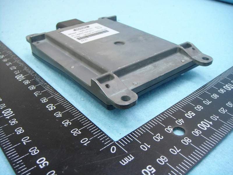
Click to zoom
Application Details
- Equipment Class
- DXX - Part 15 Low Power Communication Device Transmitter
- Date of Grant
- Sep 08, 2014
- Application Purpose
- Original Equipment
- Date of Application
- Aug 27, 2014
- Equipment Note
- 24GHz Blind Spot Detection Radar
- Frequency Range
- 24068.00000000 - 24218.00000000
- Company
- Wistron NeWeb Corporation
- Country
- Taiwan
Documents & Files
Document Text
Text extracted from the exhibit documents filed with the FCC. Open a document above to read the original.
Users Manual
24GHz Blind Spot Detection Radar User Manual V0.01 Content Blind Spot Detection Radar System ...................................................... 1 Notice: ................................................................................................. 1 Radar and Warning System location .................................................... 1 Warning level ....................................................................................... 3 Detection range and warning systems.................................................. 4 Radar detection limitation ................................................................... 6 False alarms ......................................................................................... 7 Blind spot zone and the radar viewing area ......................................... 8 FCC Statement: .................................................................................... 9 24GHz Blind Spot Detection Radar - Wistron NeWeb Corp. - 1 Blind Spot Detection Radar System 24GHz radar blind spot detection system (hereinafter referred to as BSD system) is a set of auxiliary system which uses radar sensor to detect road traffic conditions and visual blind spot area. It is to provide alert information for driver when changing lanes. This blind spot monitoring system set range includes both sides and the rear of the vehicle. The system will provide different warning level to remind drivers based on the message of indicator for changing lane once target enter the blind spot zone. Notice: Blind spot detection system is not able to detect all the cars in all cases. There is still the risk of accidents. Blind spot detection system can not be used to replace the judgment of driving on the road, do not place undue reliance on detection results. For changing lanes or similar operations, driver still needs to concentrate and observe the surrounding environment. If the rear car driving fast, blind spot detection system may not react. Blind spot detection system will start detection mechanisms with car speed 10 km / h or more. If the radar sensor system detects error, a warning light will be turned on and maintained, this system will point out the problem comes from left or right side of the sensor. Radar and Warning System location Blind spot detection system consists of two radar sensors and a warning system 24GHz Blind Spot Detection Radar - Wistron NeWeb Corp. - 2 Radar sensors are installed in the rear bumper of the left and right sides (such as schematic in Figure 1). The radars on the two sides help drivers detect vehicles. (Figure 1) If the radar sensor is obscured, it may not detect obstacles and reduce system performance. To avoid radar sensor function is affected, please pay special attention to the following points: Do not shield radar sensor foreign body parts (such as stickers, bike rack, trailer). Avoid bumper was hit or damaged, if the above situations, such as shock or damage, please contact the service center as soon as possible and repair. Ensure that the soil/ snow or ice on the site of the radar sensor has been cleared.. Warning system will be installed in the driver's seat and front passenger side A-pillar (as shown in Figure 2). (Figure 2) 24GHz Blind Spot Detection Radar - Wistron NeWeb Corp. - 3 Blind spot detection system startup and shutdown Start up After pressing the button, the button's indicator light is and the system is turned on. Shut down Pressing the button again, the indicator on the button goes off button and the system is shut down. When you turn off the system, you will not receive alerts. Blind spot detection system switch will remain in the position you set. Warning level Blind spot detection system provides the driver lance change assistance according to if driver uses indicator light when changing lane. Warning display is divided into two levels: Level One Warning: If you are on a normal driving lane and do not intend to use light indicates to change lanes, blind spot detection system only detects whether both sides would become a danger for the car to change lanes. If the relative speed and relative distance are considered to be hazardous for changing lane, warning system on A pillar will provide light alert. Level Two warning: If you use indicator to change lane and the blind spot detection system detects the danger from both sides, the warning system will provide light and audio alert. 24GHz Blind Spot Detection Radar - Wistron NeWeb Corp. - 4 Level One and Level Two warning is to remind the driving situation. Driver still needs to concentrate and observe the driving conditions. Detection range and warning systems When you start the engine / ACC (TBD), the blind spot detection system indicator will appear briefly lit and warning beep sound to confirm that the system is functioning properly. For automatic transaxle car, this system only works when the S, D gear. Blind Spot Detection System provides alert for driver assistance (As shown in Figure A). when another vehicle from behind goes into the blind spot area, referred to here as the blind spot area extending from the sides of the vehicle around the rearview mirror to a position about 3 meters away from the bumper . Blind spot detection system will active when the vehicle speed exceeds 10km/h. Level one warning will be triggered when you overtake or another vehicle comes from the front into the blind spot area with relative speed equal or less 10km/h. When the vehicle pass rapidly through the blind spot region (The relative speed is greater than 60km/h, or less than 2 seconds Time to Collision) will not trigger the alarm. Blind spot detection system does not have the ability to measure the width of the lane. The system is based on a fixed lane width to detect. The main detection range is the normal driving lane which cover two adjacent lanes. It does not 24GHz Blind Spot Detection Radar - Wistron NeWeb Corp. - 5 consider driver is driving whether in the …
Text truncated - open the document above for the full version.
Cover Letter(s)
Wistron NeWeb Corporation 20 Park Avenue II, Hsinchu Science Park, Hsinchu 308, Taiwan Tel: 886-3-666-7799 ext. 6361 / Fax: 886-3-666-7323 Confidential Letter Date: 2014/7/30 Federal Communications Commission Authorization and Evaluation Division FCC ID:NKRUMDRT1 Confidentiality Request Pursuant to Sections 0.457 and 0.459 of the Commission’s Rules, the Applicant Hereby requests confidential treatment of information accomparting this Application As outlined below: 1. Block Diagram 2. Circuit Diagram 3. Operational Description The above materials contain trade secrets and proprietary information not customarily released to the public. The public disclosure of these matters might be harmful to the Applicant and provide unjustified benefits to its competitors. The Applicant understands that pursuant to Rule 0.457, disclosure of this Application and all accompanying documentation will not be made before the date of the Grant for this application Note: The registered grantee contact is not available, Trsungfu Hsu is signing for grantee contact. He/She can be reached at email: [email protected] Sincerely, Applicant’s company name : Wistron NeWeb Corporation Applicant’s company address : 20 Park Avenue II, Hsinchu Science Park, Hsinchu 308, Taiwan Signature : Signed for Troy Chien Name and Job Title : Troy Chien / Associate Technical Director E-Mail : [email protected] Tel. : 886-3-666-7799 ext. 6361
Cover Letter(s)
Wistron NeWeb Corporation 20 Park Avenue II, Hsinchu Science Park, Hsinchu 308, Taiwan Tel: 886-3-666-7799 ext. 6361 / Fax: 886-3-666-7323 Power of Attorney Date: 2014/7/30 Dear Sir, I hereby have entrusted the following person to be a proxy regarding application for Type Certification. Sporton International Inc. Address : No.8, Lane 724, Bo-ai St., Jhubei City, HsinChu County 302, Taiwan, R.O.C. Name : Leo Huang Job Title : Manager e-mail : [email protected] I am therefore responsible for the contents of the application. Brand name and model type of the specified radio equipment: WNC / UMD-RT01 FCC ID: NKRUMDRT1 Product name: 24GHz Blind Spot Detection Radar Note: The registered grantee contact is not available, Trsungfu Hsu is signing for grantee contact. He/She can be reached at email: [email protected] FCC Grantee contact person information. Applicant’s company name : Wistron NeWeb Corporation Applicant’s company address : 20 Park Avenue II, Hsinchu Science Park, Hsinchu 308, Taiwan Signature : Signed for Troy Chien Name and Job Title : Troy Chien / Associate Technical Director E-Mail : [email protected] Tel. : 886-3-666-7799 ext. 6361
External Photos
Report No.: 2D2102-03 SPORTON International Inc. PAGE NUMBER : 1 OF 2 TEL : 886-3-327-3456 ISSUED DATE : Aug. 27, 2014 FAX : 886-3-327-0973 Photographs of EUT Report No.: 2D2102-03 SPORTON International Inc. PAGE NUMBER : 2 OF 2 TEL : 886-3-327-3456 ISSUED DATE : Aug. 27, 2014 FAX : 886-3-327-0973
ID Label/Location Info
Label: Label Location:
Internal Photos
Report No.: 2D2102-03 SPORTON International Inc. PAGE NUMBER : 1 OF 8 TEL : 886-3-327-3456 ISSUED DATE : Aug. 27, 2014 FAX : 886-3-327-0973 Photographs of EUT Report No.: 2D2102-03 SPORTON International Inc. PAGE NUMBER : 2 OF 8 TEL : 886-3-327-3456 ISSUED DATE : Aug. 27, 2014 FAX : 886-3-327-0973 Report No.: 2D2102-03 SPORTON International Inc. PAGE NUMBER : 3 OF 8 TEL : 886-3-327-3456 ISSUED DATE : Aug. 27, 2014 FAX : 886-3-327-0973 Report No.: 2D2102-03 SPORTON International Inc. PAGE NUMBER : 4 OF 8 TEL : 886-3-327-3456 ISSUED DATE : Aug. 27, 2014 FAX : 886-3-327-0973 Report No.: 2D2102-03 SPORTON International Inc. PAGE NUMBER : 5 OF 8 TEL : 886-3-327-3456 ISSUED DATE : Aug. 27, 2014 FAX : 886-3-327-0973 Report No.: 2D2102-03 SPORTON International Inc. PAGE NUMBER : 6 OF 8 TEL : 886-3-327-3456 ISSUED DATE : Aug. 27, 2014 FAX : 886-3-327-0973 Report No.: 2D2102-03 SPORTON International Inc. PAGE NUMBER : 7 OF 8 TEL : 886-3-327-3456 ISSUED DATE : Aug. 27, 2014 FAX : 886-3-327-0973 Report No.: 2D2102-03 SPORTON International Inc. PAGE NUMBER : 8 OF 8 TEL : 886-3-327-3456 ISSUED DATE : Aug. 27, 2014 FAX : 886-3-327-0973
Test Report
SPORTON International Inc. No. 52, Hwa Ya 1st Rd., Kwei-Shan Hsiang, TaoYuan Hsien, Taiwan, R.O.C. Ph: 886-3-327-3456 / FAX: 886-3-327-0973 / www.sporton.com.tw Report Format Version: 01 FCC RADIO TEST REPORT Applicant’s company Wistron NeWeb Corporation Applicant Address 20 Park Avenue II, Hsinchu Science Park, Hsinchu 308, Taiwan FCC ID NKRUMDRT1 Manufacturer’s company Wistron NeWeb Corporation Manufacturer Address 20 Park Avenue II, Hsinchu Science Park, Hsinchu 308, Taiwan Product Name 24GHz Blind Spot Detection Radar Brand Name WNC Model Name UMD-RT01 Test Rule Part(s) 47 CFR FCC Part 15 Subpart C § 15.249 Test Freq. Range 24068MHz ~24218MHz Received Date Dec. 21, 2012 Final Test Date Dec. 29, 2012 Submission Type Original Equipment Statement The test result in this report refers exclusively to the presented test model / sample. Without written approval of SPORTON International Inc., the test report shall not be reproduced except in full. The measurements and test results shown in this test report were made in accordance with the procedures and found in compliance with the limit given in ANSI C63.10-2009 and 47 CFR FCC Part 15 Subpart C. The test equipment used to perform the test is calibrated and traceable to NML/ROC. Report No.: FR2D2102-03 Report Format Version: 01 Page No. : i of ii FCC ID: NKRUMDRT1 Issued Date : Aug. 27, 2014 Table of Contents 1 CERTIFICATE OF COMPLIANCE ......................................................................................................................... 1 2 SUMMARY OF THE TEST RESULT .......................................................................................................................... 2 3 GENERAL INFORMATION .................................................................................................................................. 3 3.1 Product Details....................................................................................................................................................................................3 3.2 Accessories .........................................................................................................................................................................................3 3.3 Table for Carrier Frequencies .............................................................................................................................................................3 3.4 Table for Test Modes ...........................................................................................................................................................................4 3.5 Table for Testing Locations..................................................................................................................................................................4 3.6 Table for Supporting Units ...................................................................................................................................................................4 3.7 Test Configurations .............................................................................................................................................................................5 4 TEST RESULT ..................................................................................................................................................... 6 4.1 Field Strength of Fundamental Emissions Measurement .....................................................................................................................6 4.2 20dB Spectrum Bandwidth Measurement ........................................................................................................................................11 4.3 Radiated Emissions Measurement ....................................................................................................................................................15 4.4 Band Edge Emissions Measurement .................................................................................................................................................25 5 LIST OF MEASURING EQUIPMENTS ................................................................................................................... 28 6 MEASUREMENT UNCERTAINTY.......................................................................................................................... 30 APPENDIX A. TEST PHOTOS ........................................................................................................................ A1 ~ A3 Report No.: FR2D2102-03 Report Format Version: 01 Page No. : ii of ii FCC ID: NKRUMDRT1 Issued Date : Aug. 27, 2014 History of This Test Report REPORT NO. VERSION DESCRIPTION ISSUED DATE FR2D2102-03 Rev. 01 Initial issue of report Aug. 27, 2014 47 CFR FCC Part 15 Subpart C 2.7 2.8 Report No.: FR2D2102-03 Report Format Version: 01 Page No. : 2 of 30 FCC ID: NKRUMDRT1 Issued Date : Aug. 27, 2014 2 SUMMARY OF THE TEST RESULT Applied Standard: 47 CFR FCC Part 15 Subpart C Part Rule Section Description of Test Result Under Limit 4.1 15.249(a) Field Strength of Fundamental Emissions Complies 9.02 dB 4.2 15.215(c) 20dB Spectrum Bandwidth Complies - 4.3 15.249(a)/(d) Radiated Emissions Complies 0.515 dB 4.4 15.249(d) Band Edge Emissions Complies 11.33 dB 4.5 15.203 Antenna Requirements Complies - Report No.: FR2D2102-03 Report Format Version: 01 Page No. : 3 of 30 FCC ID: NKRUMDRT1 Issued Date : Aug. 27, 2014 3 GENERAL INFORMATION 3.1 Product Details Items Description Power Type From DC Battery 13.5V Modulation FMCW Frequency Range 24068MHz ~24218MHz Channel Number 1536 Channel Band Width (99%) 2.34 MHz Max. Field Strength 104.98 dBuV/m at 1.5m (Average) Carrier Frequencies Please refer to section 3.3 Antenna TX: PATCH array Antenna, Antenna Gain: 14dBi (Without any antenna connector) RX: PATCH array Antenna, Antenna Gain: 13dBi (Without any antenna connector) 3.2 Accessories N/A 3.3 Table for Carrier Frequencies Fre…
Text truncated - open the document above for the full version.
Test Setup Photos
Report No.: FR2D2102-03 FCC ID: NKRUMDRT1 Page No. : A1 of A3 Appendix A. Test Photos Report No.: FR2D2102-03 FCC ID: NKRUMDRT1 Page No. : A2 of A3 1. Photographs of Radiated Emissions Test Configuration Test Configuration: 30MHz~1GHz FRONT VIEW REAR VIEW Report No.: FR2D2102-03 FCC ID: NKRUMDRT1 Page No. : A3 of A3 Test Configuration: Above 1GHz FRONT VIEW REAR VIEW
Contact Information
Applicant
William Su(Senior Director / System Engineering dept.)
Technical Contact
Sporton International Inc.Christy Fan
[email protected]886-3-656-9065
No.8, Lane 724, Bo-ai St. · Taiwan
Non-Technical Contact
Sporton International Inc.Christy Fan
[email protected]886-3-656-9065
Test Firm
SPORTON International Inc.Leo Huang
Technical Specifications
| # | Rule Parts | Frequency Range | Power Output |
|---|---|---|---|
| 1 | 15C | 24.07 GHz - 24.22 GHz | - |
Other Applications from Wistron NeWeb Corporation
NKR-ATTCGW453
Aug 25, 2026Enterprise product
Equipment Class
NII - Unlicensed National Information Infrastructure TXNKR-LS06B
Aug 24, 2026Touchscreen
Equipment Class
NII - Unlicensed National Information Infrastructure TXNKR-DWSZW
Aug 10, 2026Door/Window Sensor
Equipment Class
DXX - Part 15 Low Power Communication Device TransmitterNKR-TELE2
Jun 26, 2026TELE2
Equipment Class
NII - Unlicensed National Information Infrastructure TXNKR-VMC-SA525MAX
Jun 05, 2026NAD (Network Access Device)
Equipment Class
CXX - Communications Rcvr for use w/ licensed Tx and CBs