NKRUPASY001Satellite Radio Receiver
Wistron NeWeb Corporation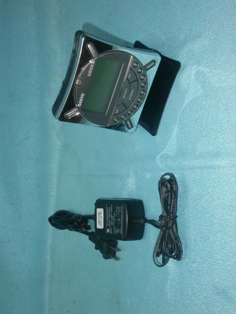
Click to zoom
Application Details
- Equipment Class
- DXX - Part 15 Low Power Communication Device Transmitter
- Date of Grant
- Jul 08, 2004
- Application Purpose
- Original Equipment
- Date of Application
- Jul 08, 2004
- Equipment Note
- Satellite Radio Receiver
- Frequency Range
- 88.10000000 - 107.90000000
- Company
- Wistron NeWeb Corporation
- Country
- Taiwan
Documents & Files
Document Text
Text extracted from the exhibit documents filed with the FCC. Open a document above to read the original.
Users Manual
CRSR-10 User Guide © 2004 SIRIUS Satellite Radio Inc. Sanyo Fisher Co. 21605 Plummer St. Chatsworth, CA 91311 www.sanyo.com SIRIUS Satellite Radio 1221 Avenue of the Americas New York, NY 10020 (888) 539-7474 www.sirius.com CRSR-10 (June 2004) Sanyo CRSR-10 User GuideSanyo CRSR-10 User Guide CONGRATULATIONS! Your new Sanyo™ CRSR-10 portable Plug-n-Play receiver lets you enjoy SIRIUS ® Satellite Radio’s digital entertainment in your car, home, office, or boat. You may also purchase the Sanyo BMBX-10 Portable Boombox for an enhanced listening experience. Use this manual to familiarize yourself with all of CRSR-10’s features and capabilities. Box Contents.................................................................... 3 Safety Precautions.......................................................... 4 Installation in a Vehicle.................................................... 6 Installation in a Home or Office....................................... 9 Sanyo Controls and Features....................................... 10 Activating your SIRIUS Subscription............................ 12 Basic Operation............................................................. 13 Changing Channels.................................................. 13 Search Modes (Category, Channel, Artist, Song) .. 14 Direct Tuning............................................................. 15 Setting Channel Presets........................................... 16 Recalling Channel Presets....................................... 16 Searching for a Channel Preset (P.TUNE Mode)..... 16 Preset Tune List Mode............................................. 17 Memory (MEMO) and Song Seek (S-Seek) Functions18 Menu Display Options.................................................... 21 Table of Contents Box Contents If anything is missing or damaged, or if your Sanyo CRSR-10 fails to operate, notify your dealer immediately. It is recommended that you retain the original carton and packing materials in case you need to ship your CRSR-10 in the future. SIRIUS ID ................................................................... 21 Wireless FM Transmitter......................................... 22 Display Settings....................................................... 24 Antenna Aiming........................................................ 25 Confirm Tone Options.............................................. 25 Lock Options............................................................ 26 Audio Level.............................................................. 27 Memory Options....................................................... 27 Time-Based Features.............................................. 28 Factory Default........................................................ 30 Changing the Removable Faceplates.......................... 31 Troubleshooting............................................................ 32 Specifications................................................................ 33 Optional Accessories................................................... 34 Warranty....................................................................... 38 Important Information.................................................... 39 3 2 1 x CRSR-10 & 3 x Faceplates 1 x Home Stand 1 x Windshield Mount 1 x Audio Jacks1 x Car Adaptor1 x Home Power Cord 1 x Car Antenna 1 x Adaptor1 x Home Antenna For the latest information about this and other Sanyo products, visit www.sanyo.com Unpack your Sanyo CRSR-10 and accessories carefully and make sure that everything listed here is present: Sanyo CRSR-10 User GuideSanyo CRSR-10 User Guide Warning Take the following precautions to prevent fire and avoid personal injury: • To avoid short circuits, never put or leave any metallic objects (coins, tools, etc.) inside the unit. • If the unit emits smoke or unusual odors, turn the power off immediately and consult your Sanyo retailer. • Do not drop the unit or subject it to strong shocks. • If the LCD display becomes damaged or broken, do not touch the liquid crystal fluid. The fluid can be dangerous to your health. If the liquid crystal fluid contacts your body or clothing, immediately wash it off with soap and water. Caution Take the following precautions to keep the unit in proper working order: • Be sure the unit is connected to a 12V DC power supply with a negative ground connection. • Do not open the unit. • Do not install the unit where it will be exposed to high levels of humidity, moisture, or dust. • When replacing a fuse, use only a new one with the proper rating. Using a fuse with the wrong rating may cause the unit to malfunction. • To prevent a short circuit when replacing a fuse, first disconnect the wiring harness. Note: If the unit doesn’t seem to be working properly: • Turn the unit’s power off, wait 5 – 10 seconds, then turn the power on again. • If the unit still malfunctions, turn the unit’s power off, remove it from the cradle, wait 5 – 10 seconds, replace it in the cradle and turn the power back on. If the problem persists, consult your Sanyo retailer. FCC Warning This equipment may generate or use radio frequency energy. Changes or modifications to this equipment may cause harmful interference unless the modifications are expressly approved in this User Guide. The user could lose the authority to operate this equipment if an unauthorized change or modification made. 5 4 Safety Precautions Warning Take the following precautions to prevent traffic accidents and avoid personal injury: • Installation must be performed according to this user guide. Sanyo is not responsible for issues arising from installations not performed according to the procedures in this manual. • Do not install the unit where it may obstruct your view through the windshield or of your vehicle’s indicator displays. • Do not install the unit where it may hinder the function of safety devices such as an airbag. Doing so may prevent the airbag from functioning properly in th…
Text truncated - open the document above for the full version.
External Photos
Company : Wistron NeWeb Corporation Page : 1 of 3 Product : Satellite Radio Receiver Model : UPA-SY Company : Wistron NeWeb Corporation Page : 2 of 3 Product : Satellite Radio Receiver Model : UPA-SY Company : Wistron NeWeb Corporation Page : 3 of 3 Product : Satellite Radio Receiver Model : UPA-SY External photo of Adapter
ID Label/Location Info
Company : Wistron NeWeb Corporation Model : UPA-SY Product : Satellite Radio Receiver Satellite Radio Receiver Model No: UPA-SY FCC IDNKRUPASY001 This device complies with part 15 of the FCC Rules. Operation is subject to the following two conditions: [1] this device may not cause harmful interference and [2] this device must accept any interference received, including interference that may cause undesired operation. S/N Made in Taiwan
Internal Photos
Company : Wistron NeWeb Corporation Page : 1 of 21 Product : Satellite Radio Receiver Model : UPA-SY Internal photo of EUT Company : Wistron NeWeb Corporation Page : 2 of 21 Product : Satellite Radio Receiver Model : UPA-SY Company : Wistron NeWeb Corporation Page : 3 of 21 Product : Satellite Radio Receiver Model : UPA-SY Company : Wistron NeWeb Corporation Page : 4 of 21 Product : Satellite Radio Receiver Model : UPA-SY Company : Wistron NeWeb Corporation Page : 5 of 21 Product : Satellite Radio Receiver Model : UPA-SY Company : Wistron NeWeb Corporation Page : 6 of 21 Product : Satellite Radio Receiver Model : UPA-SY Company : Wistron NeWeb Corporation Page : 7 of 21 Product : Satellite Radio Receiver Model : UPA-SY Company : Wistron NeWeb Corporation Page : 8 of 21 Product : Satellite Radio Receiver Model : UPA-SY Company : Wistron NeWeb Corporation Page : 9 of 21 Product : Satellite Radio Receiver Model : UPA-SY Company : Wistron NeWeb Corporation Page : 10 of 21 Product : Satellite Radio Receiver Model : UPA-SY Company : Wistron NeWeb Corporation Page : 11 of 21 Product : Satellite Radio Receiver Model : UPA-SY Company : Wistron NeWeb Corporation Page : 12 of 21 Product : Satellite Radio Receiver Model : UPA-SY Company : Wistron NeWeb Corporation Page : 13 of 21 Product : Satellite Radio Receiver Model : UPA-SY Company : Wistron NeWeb Corporation Page : 14 of 21 Product : Satellite Radio Receiver Model : UPA-SY Company : Wistron NeWeb Corporation Page : 15 of 21 Product : Satellite Radio Receiver Model : UPA-SY Company : Wistron NeWeb Corporation Page : 16 of 21 Product : Satellite Radio Receiver Model : UPA-SY Company : Wistron NeWeb Corporation Page : 17 of 21 Product : Satellite Radio Receiver Model : UPA-SY Company : Wistron NeWeb Corporation Page : 18 of 21 Product : Satellite Radio Receiver Model : UPA-SY Company : Wistron NeWeb Corporation Page : 19 of 21 Product : Satellite Radio Receiver Model : UPA-SY Internal photo of Adapter Company : Wistron NeWeb Corporation Page : 20 of 21 Product : Satellite Radio Receiver Model : UPA-SY Company : Wistron NeWeb Corporation Page : 21 of 21 Product : Satellite Radio Receiver Model : UPA-SY
Operational Description
WNC CONFIDENTIAL Rev. 4 Sheet 1 of 8 Design Specification Model: UPA-SY 1.0 INTERFACE REQUIREMENTS WNC CONFIDENTIAL Rev. 4 Sheet 2 of 8 1.1 HARDWARE BLOCK DIAGRAM 1.2 INPUT INTERFACE z Input power supply The UPA-SY work on 12VDC input, and maximum current less 1.5A. Ripple Noise less 100mVp-p z Input RF signal Power Level: -95dBm~ +5dBm Frequency: 2.3~2.4G Modulation: QPSK 1.3 OUTPUT INTERFACE z Audio Line out Audio Level: 0~-9dB Quality: Must meet RX55 specification z Audio Earphone out Audio Level: 0~-9dB z FM transmitter Frequency: 88.1~107.9MHz Quality: Must meet RX57 specification SOFTWARE/firmware REQUIREMENTS WNC CONFIDENTIAL Rev. 4 Sheet 3 of 8 1.4 CPU/MIPS SPECIFICATION The firmware shall operate on an Atmega32 8-bit micro-controller running at a clock of at least 7MHz. 1.5 OS REQUIREMENT The firmware shall operate without OS. A proprietary task switching mechanism will be implemented, instead. 1.6 MEMORY REQUIREMENT The firmware shall require no more than 32KB program memory and no more than 2KB data memory. No more than 1KB of EEPROM shall be needed for power-off parameter storage. 1.7 USER INTERFACE REQUIREMENT The product shall provide an user interface similar to JVC PnP XXX whenever possible. The operational menu tree is described in document XXX.....[more descriptions about UI] 1.8 PROTOCOL REQUIREMENT The CPU of this product communicates with SSM module with SSP protocol. The firmware consists of SSP API provided by Sirius. The infrared remote control signal is a NEC repeat-pulse protocol. [more description about communication protocols] WNC CONFIDENTIAL Rev. 4 Sheet 4 of 8 2.0 PERFORMANCE REQUIREMENTS 2.1 BASELINE BER TESTING COFDM: CNR: 9dB Power Level: -77dBm Test Period: 15 seconds Test Criteria: 5E-2 max CNR: 7.5dB Power Level: -74.5dBm Test Period: 15 seconds Test Criteria: 8E-2 max TDM1 & TDM2: CNR: 10dB Power Level: -74dBm Test Period: 15 second Test Criteria: 5E-2 max CNR: 6.4dB Power Level: -78dBm Test Period: 15 second Test Criteria: 8E-2 max 2.2 BER VS. CNR TEST COFDM: Power level: -60, -65, -70dBm Test Period: 15 second Test Criteria: Refer Table Table COFDM vs. CNR Limit CNR (dB) COFDM BER Limit 6 2.0E-1 7 1.5E-1 8 1.0E-1 9 6.5E-2 10 3.5E-2 11 2.0E-2 12 9.5E-3 13 4.0E-3 14 1.5E-3 15 5.0E-4 16 2.0E-4 17 6.0E-5 18 1.5E-5 19 1.0E-5 20 5.0E-6 TDM1 & TDM2: Power Level: -60, -65, 70dBm Test Period: 15 second Test Criteria: Refer table Table TDM BER vs. CNR Limits CNR (dB) TDM BER Limits 4 1.3E-1 5 9.2E-2 6 5.6E-2 7 3.1E-2 8 1.5E-2 9 7.0E-3 10 2.5E-3 WNC CONFIDENTIAL Rev. 4 Sheet 5 of 8 11 7.5E-4 12 1.8E-4 13 4.9E-5 14 7.2E-6 15 1.4E-6 2.3 BER PERFORMANCE- INPUT AMPLITUDE DYNAMIC RANGE COFDM: Noise: 15.75dB at –85dBm 20.75dB at –80dBm -75~+4dBm noise off Power Level: 5dB step from –85dBm to +4dBm Test Period: 15 second Test Criteria: 5E-2 max TDM1 & TDM2 Noise: 11.75dB at –89dBm 15.75dB at –85dBm 20.75dB at –80dBm -75~-55dBm noise off Power Level: 5dB step form -89dBm to -55dBm Test Period: 15 second Test Criteria: 5E-2 2.4 BER PERFORMANCE- INPUT FREQUENCY DYNAMIC RANGE (DOPPLER SHIFT) COFDM: CNR: 9dB Power Level: -77dBm Frequency: a. 2326.25MHz to 2326.2495MHz. b. 2326.25MHz to 2326.2505MHz Test Period: 15 second Test Criteria: 5E-2 TDM1 & TDM2: CNR: 10dBm Power Level: -74dBm Frequency: a. 2322.293MHz to 2322.255MHz b. 2322.293 MHz to 2322.331MHz Test Period: 15 second Test Criteria: 5E-2 2.5 BER PERFORMANCE - OUT OF BAND INTERFERENCE COFDM: CNR: 17.9dB Power Level: -67dBm Test Criteria: 5E-2 TDM1 & TDM2: CNR: 10.4dBm Power Level: -71dBm Test Period: 15 second Test Criteria: 5E-2 Out of band interference table Frequency (MHz) Amplitude at TDM port of DLP (dBm) Amplitude at COFDM port of DLP (dBm) 837(CW) -23 -28 915(CW) -23 -28 1990(IS95 MOD) -23 -28 2338.75(XM MOD) -35 -44 2400(CW) -21 -32 2.6 BER PERFORMANCE - COFDM AGC TEST COFDM: Setup refer to Sirius document RX000055 page 48~49 Test Criteria: >178dB/Sec WNC CONFIDENTIAL Rev. 4 Sheet 6 of 8 2.7 BER PERFORMANCE-XM INTERFERENCE TEST W/LNA TDM1 & TDM2: Setup refer to Sirius document RX000055 page 50~52 Test Criteria: >-29dBm 2.8 AUDIO PERFORMANCE-THDPN The total harmonic distortion plus noise for each channel must less than 0.2% for 1KHz –2dB input. 2.9 AUDIO PERFORMANCE-SNR SNR in each channel must be greater than 80 dB. 2.10 AUDIO PERFORMANCE-FREQUENCY RESPONSE Test Setup refers RX55 section 8.6 For 14.5 kHz, the result must be in the window of [-1.7 dBr to + 0.3 dBr] for both left and right channels [7.25 kHz = 0 dBr]. For 14.8 kHz, the result must be in the window of [-6.5 dBr to +0.0 dBr] for both left and right channels [7.25 kHz = 0 dBr]. For 20 Hz, the result must be in the window of [-3.0 dBr to +3.0 dBr] for both left and right channels [7.25 kHz = 0 dBr]. 2.11 AUDIO PERFORMANCE-FREQUENCY RESPONSE Test Setup refers RX55 section 8.6 For 100Hz, the result must be in the window of [-1.0 dBr to + 1.0 dBr] for both left and right channels [7.2kHz = 0 dBr]. For 300Hz, the result must be in the window of [-1.0 dBr to + 1.0 dBr] for both left and right channels [7.2kHz = 0 dBr]. For 500Hz, the result must be in the window of [-1.0 dBr to + 1.0 dBr] for both left and right channels [7.2kHz = 0 dBr]. For 1kHz, the result must be in the window of [-1.0 dBr to + 1.0 dBr] for both left and right channels [7.2kHz = 0 dBr]. For 2kHz, the result must be in the window of [-1.0 dBr to + 1.0 dBr] for both left and right channels [7.2kHz = 0 dBr]. For 4kHz, the result must be in the window of [-1.0 dBr to + 1.0 dBr] for both left and right channels [7.2kHz = 0 dBr]. For 12k Hz, the result must be in the window of [-1.0 dBr to + 1.0 dBr] for both left and right channels [7.2kHz = 0 dBr]. 2.12 FM-MODULATED AUDIO MODULATION LEVEL Test Setup refers RX57 section 5.1 For Stream 223, the waveform is stable 0.5 seconds after periodic silence at -10dBFS, 1KHz L+R Sine wave. Bandwidth 20~20KHZ Modulation Level: 48~72% For Stream 184, the waveform is stable 4 seconds after periodic silence at -2.97dBFS, 1KHz…
Text truncated - open the document above for the full version.
Test Report
Ecom Sertech Corp. Rm. 258, Bldg. 17, NO.195, Sec. 4 Chung Hsing Rd.,Chu -Tung Chen, Hsinchu, Taiwan 310, R.O.C TEL:886 - 3 - 5918012 FAX : 886 - 3 - 5825720 FCC ID :NKRUPASY001 Report No.:ER04-06-064FRF Page 1 of 42 TEST REPORT Product Name : Satellite Radio Receiver Model Number : UPA-SY Brand Name : Sanyo FCC ID : NKRUPASY001 Applicant : Wistron NeWeb Corporation Address : No. 10-1, Li-hsin Road I, Hsinchu Science Park, Hsinchu 300, Taiwan, R.O.C. Received Date : June 24, 2004 Tested Date : June 24 ~ 30, 2004 Notes : 1. This report will be invalid if duplicated or photocopied in part. 2. This report refers only to the specimen(s) submitted to testing, and be invalid as separately used. 3. This report is invalid without examination stamp and signature of this institute. 4. The tested specimen(s) will be preserved for thirty days from the data issued. 5. The report must not be used to claim product certification, approval, or endorsement by NVLAP, NIST, or any agency of the federal government. Ecom Sertech Corp. Rm. 258, Bldg. 17, NO.195, Sec. 4 Chung Hsing Rd.,Chu -Tung Chen, Hsinchu, Taiwan 310, R.O.C TEL:886 - 3 - 5918012 FAX : 886 - 3 - 5825720 FCC ID :NKRUPASY001 Report No.:ER04-06-064FRF Page 2 of 42 Test Report Certification Product Name : Satellite Radio Receiver Model Number : UPA-SY Brand Name : Sanyo FCC ID : NKRUPASY001 Applicant : Wistron NeWeb Corporation . Measurement Standard : FCC 47 C.F.R. Part 15, Subpart B and Subpart C (2003) ANSI C63.4 (2001) WE HEREBY CERTIFY THAT: The measurements shown in the attachment were made in accordance with the procedures indicated, and the energy emitted by the equipment was found to be within the limits applicable. We assume full responsibility for the accuracy and completeness of these measurements and vouch for the qualifications of all persons taking them. Ecom Sertech Corp. Rm. 258, Bldg. 17, NO.195, Sec. 4 Chung Hsing Rd.,Chu -Tung Chen, Hsinchu, Taiwan 310, R.O.C TEL:886 - 3 - 5918012 FAX : 886 - 3 - 5825720 FCC ID :NKRUPASY001 Report No.:ER04-06-064FRF Page 3 of 42 TABLE OF CONTENTS TITLE PAGE NO. 1. GENERAL INFORMATION ................................................................................................... 5 1.1 General Statement .................................................................................................................................5 1.2 General Description of EUT & Power ..................................................................................................5 1.3 EUT & Peripherals Setup Diagram.......................................................................................................6 1.4 EUT Operating Procedure.....................................................................................................................6 1.5 Description of Laboratory.....................................................................................................................6 1.6 Summary of Test Results ......................................................................................................................7 2. CONDUCTED POWERLINE TEST....................................................................................... 8 2.1 Test Equipments ...................................................................................................................................8 2.2 Test Setup .............................................................................................................................................8 2.3 Conducted Power Line Emission Limit ................................................................................................9 2.4 Test Procedure ......................................................................................................................................9 2.5 Uncertainty of Conducted Emission .....................................................................................................9 2.6 Conducted RF Voltage Measurement ...................................................................................................10-11 2.7 Photos of Conduction Test....................................................................................................................12 3. RADIATED EMISSION TEST ................................................................................................ 13 3.1 Test Equipments ...................................................................................................................................13 3.2 Test Setup .............................................................................................................................................13 3.3 Radiation Limit .....................................................................................................................................14 3.4 Test Procedures.....................................................................................................................................15 3.5 Uncertainty of Radiated Emission ........................................................................................................15 3.6 Radiated RF Noise Measurement .........................................................................................................16-34 3.7 Photos of Open Site ..............................................................................................................................35-36 4. OCCUPIED BANDWIDTH MEASUREMENT..................................................................... 37 4.1 Test Equipments ...................................................................................................................................37 4.2 Test Setup .............................................................................................................................................37 4.3 Limits of 6dB Bandwidth Measurement ...............................................................................................37 4.4 …
Text truncated - open the document above for the full version.
Test Setup Photos
Ecom Sertech Corp. Rm. 258, Bldg. 17, NO.195, Sec. 4 Chung Hsing Rd.,Chu -Tung Chen, Hsinchu, Taiwan 310, R.O.C TEL:886 - 3 - 5918012 FAX : 886 - 3 - 5825720 FCC ID :NKRUPASY001 Report No.:ER04-06-064FRF Page 12 of 42 2.7 Photos of Conduction Test
Test Setup Photos
Ecom Sertech Corp. Rm. 258, Bldg. 17, NO.195, Sec. 4 Chung Hsing Rd.,Chu -Tung Chen, Hsinchu, Taiwan 310, R.O.C TEL:886 - 3 - 5918012 FAX : 886 - 3 - 5825720 FCC ID :NKRUPASY001 Report No.:ER04-06-064FRF Page 35 of 42 3.7 Photos of Open Site Ecom Sertech Corp. Rm. 258, Bldg. 17, NO.195, Sec. 4 Chung Hsing Rd.,Chu -Tung Chen, Hsinchu, Taiwan 310, R.O.C TEL:886 - 3 - 5918012 FAX : 886 - 3 - 5825720 FCC ID :NKRUPASY001 Report No.:ER04-06-064FRF Page 36 of 42
Contact Information
Applicant
William Su(Senior Director / System Engineering dept.)
Test Firm
ECOM Sertech Corp.C. Wu
Technical Specifications
| # | Rule Parts | Frequency Range | Power Output |
|---|---|---|---|
| 1 | 15C | 88.1 MHz - 107.9 MHz | - |
Other Applications from Wistron NeWeb Corporation
NKR-ATTCGW453
Aug 25, 2026Enterprise product
Equipment Class
NII - Unlicensed National Information Infrastructure TXNKR-LS06B
Aug 24, 2026Touchscreen
Equipment Class
NII - Unlicensed National Information Infrastructure TXNKR-DWSZW
Aug 10, 2026Door/Window Sensor
Equipment Class
DXX - Part 15 Low Power Communication Device TransmitterNKR-TELE2
Jun 26, 2026TELE2
Equipment Class
NII - Unlicensed National Information Infrastructure TXNKR-VMC-SA525MAX
Jun 05, 2026NAD (Network Access Device)
Equipment Class
CXX - Communications Rcvr for use w/ licensed Tx and CBs