NKRUSB400WLAN USB Adapter
Wistron NeWeb Corporation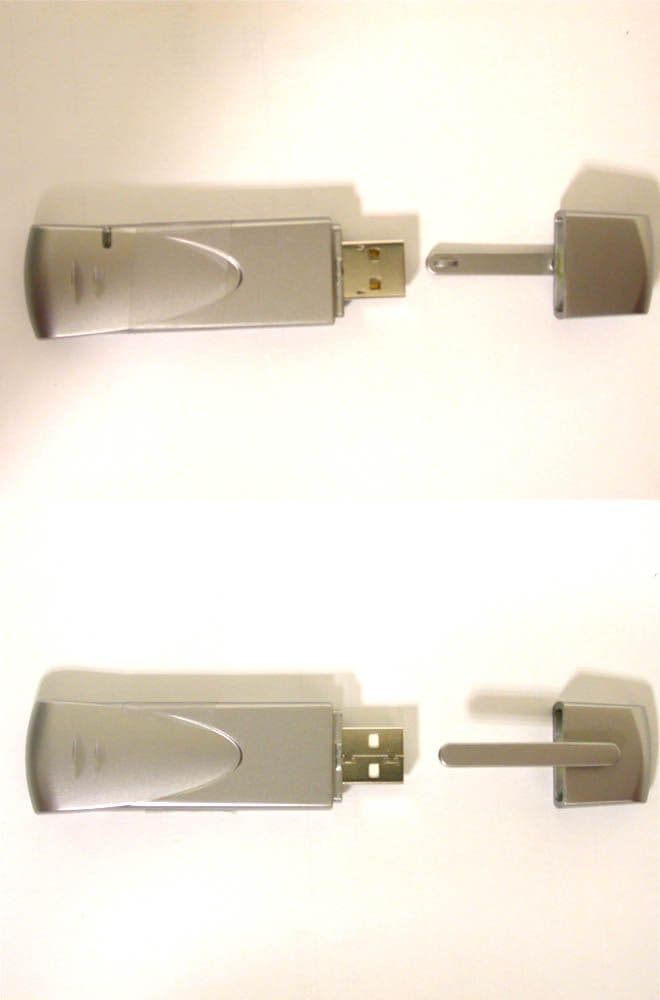
Click to zoom
Application Details
- Equipment Class
- DTS - Digital Transmission System
- Date of Grant
- Feb 16, 2003
- Application Purpose
- Original Equipment
- Date of Application
- Feb 16, 2003
- Equipment Note
- WLAN USB Adapter
- Frequency Range
- 2412.00000000 - 2462.00000000
- Company
- Wistron NeWeb Corporation
- Country
- Taiwan
Documents & Files
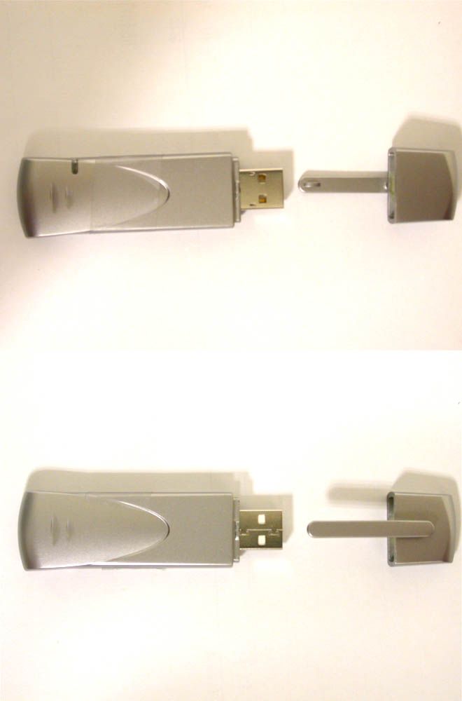
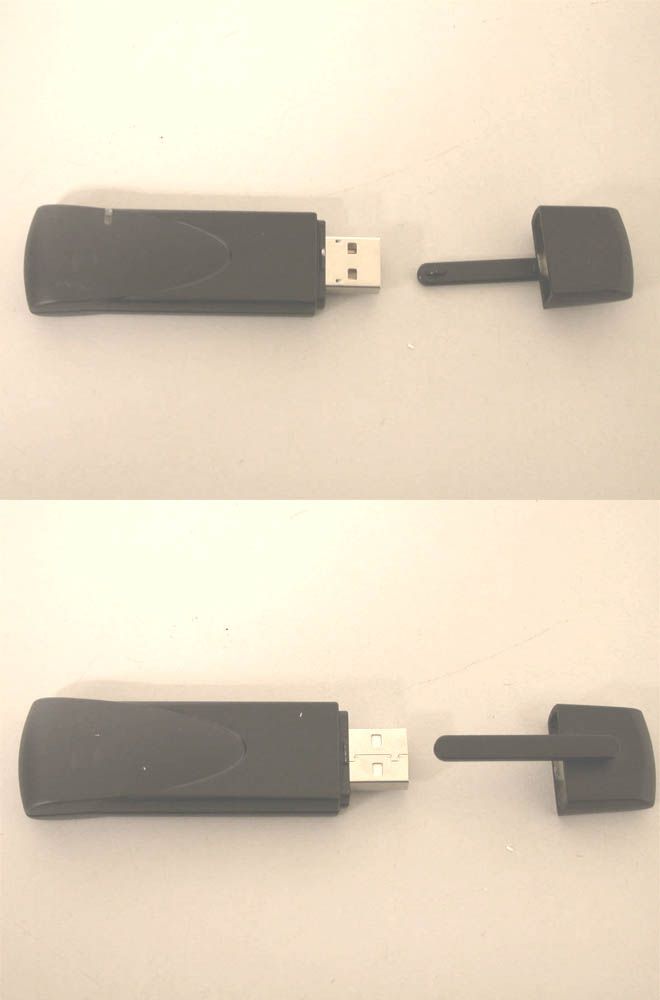
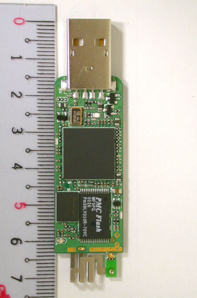
Document Text
Text extracted from the exhibit documents filed with the FCC. Open a document above to read the original.
Users Manual
802.11b WLAN USB Adapter USB-400 User’s Guide Version: 1.0 (USB-400) — Dec 2002 1 Copyright Statement No part of this publication may be reproduced, stored in a retrieval system, or transmitted in any form or by any means, whether electronic, mechanical, photocopying, recording or otherwise without the prior writing of the publisher. Windows ™ 98SE/2000/ME/XP/CE are trademarks of Microsoft ® Corp. Pentium is trademark of Intel. All copyright reserved. 2 Regulatory Information Note! Please use USB extension cable or swivel adapter to avoid human contact or approach of your 802.11b WLAN USB Adapter during normal operation. Federal Communication Commission Interference Statement This equipment has been tested and found to comply with the limits for a Class B digital device, pursuant to Part 15 of the FCC Rules. These limits are designed to provide reasonable protection against harmful interference in a residential installation. This equipment generates, uses and can radiate radio frequency energy and, if not installed and used in accordance with the instructions, may cause harmful interference to radio communications. However, there is no guarantee that interference will not occur in a particular installation. If this equipment does cause harmful interference to radio or television reception, which can be determined by turning the equipment off and on, the user is encouraged to try to correct the interference by one of the following measures: - Reorient or relocate the receiving antenna. - Increase the separation between the equipment and receiver. - Connect the equipment into an outlet on a circuit different from that to which the receiver is connected. - Consult the dealer or an experienced radio/TV technician for help. FCC Caution: To assure continued compliance, (example - use only shielded interface cables when connecting to computer or peripheral devices) any changes or modifications not expressly approved by the party responsible for compliance could void the user's authority to operate this equipment. This device complies with Part 15 of the FCC Rules. Operation is subject to the following two conditions: (1) This device may not cause harmful interference, and (2) this device must accept any interference received, including interference that may cause undesired operation. IMPORTANT NOTE: FCC Radiation Exposure Statement: This equipment complies with FCC radiation exposure limits set forth for an uncontrolled environment. This transmitter must not be co-located or operating in conjunction with any other antenna or transmitter. 3 Table of Contents Regulatory Information________________________________________________2 1. Welcome__________________________________________________________4 1.1 Kit Contents______________________________________________________5 1.2 Main Features of 802.11b WLAN USB Adapter________________________6 1.3 Wireless Networking Scenarios______________________________________7 1.4 Advantages for Using Wireless Network______________________________9 2. Quick Start to Wireless Networking___________________________________10 2.1 Installation______________________________________________________10 2.2 Connecting to an Exiting Network__________________________________12 2.3 Additional Note for Windows XP___________________________________13 3. Step-by-Step Installation Guide_______________________________________14 3.1 Install the IEEE802.11b WLAN Driver / Utility_______________________15 3.1.1 Additional Setup Processes________________________________19 3.2 Verifying the Driver/Utility________________________________________20 3.3 IEEE802.11b WLAN Utility________________________________________21 3.3.1 Disable Windows XP Zero-Configuration__________________22 3.4 Basic Setting for Infrastructure Mode_______________________________23 3.5 Basic Setting for 802.11Ad Hoc Mode/Ad Hoc Mode___________________24 3.6 Advanced Settings________________________________________________26 3.7 Encryption Function______________________________________________27 3.8 Remove your 802.11b WLAN USB Adapter__________________________29 3.9 Uninstall the IEEE802.11b WLAN Utility / Driver_____________________30 4. Using the Utility___________________________________________________31 4.1 LAN Status Tab__________________________________________________31 4.2 Link Information Tab_____________________________________________32 4.3 Site Survey Tab__________________________________________________32 4.4 Diagnostic Tab___________________________________________________33 4.5 About Tab______________________________________________________33 5. Network Application_______________________________________________34 5.1 Surveying the Network Neighborhood_______________________________34 5.2 File Sharing_____________________________________________________35 5.3 Using the Shared Folder___________________________________________36 6. Product Specifications______________________________________________37 4 1. Welcome Thank you for purchasing our 802.11b WLAN USB Adapter, and welcome to Wireless LAN—the easy way to wireless networking. This user guide introduces to you the 802.11b WLAN USB Adapter and describes the most common configurations, which will help you connect to your network easily. Please read this manual to get familiar with the IEEE802.11b Wireless LAN. This manual contains detailed instructions in operation of this product. Please keep this manual for future reference. As this product is designed to run under Microsoft Windows, it is recommended that to be installed by people who are familiar with the installation procedures for network operating systems under Microsoft Windows. 5 1.1 Kit Contents The 802.11b WLAN USB Adapter kit should include the following items: One 802.11b WLAN USB Adapter, one USB Cable, one CD and one Quick Start Guide. a. One 802.11b WLAN USB Adapter b. One USB Extension Cable c. One Swivel Adapter (Optional) d. One Software CD including: 1. Utility & Driver Installati…
Text truncated - open the document above for the full version.
Users Manual
American Telecommunications Certification Body Inc. 6731 Whittier Ave, McLean, VA 22101 February 2, 2003 RE: Winston Ne Web FCC ID: NKRUSB400 I have a few comments on this Application. 1.) In the future, please segregate photographs into External and Internal exhibits. 2.) Although there are two oscillators listed on the block diagram, the diagram seems to not comply with the provisions of 2.1033(a)(5) where the signal path and frequency shall be listed at each block. Please review. 3.) Two manuals were uploaded. Which one should be used for review? I examined the most recent upload according to the date the files was created on our server. That one has references to 20cm separation distance between the user and device. This is not appropriate when a SAR report is presented. 4.) The Schematics reference an “Optional Populated” section. This is not appropriate. Only testing performed with and without the optional components could be accepted by the Commission for filing under a single FCC ID, or filing as a fully populated device only. 5.) The SAR report in Section 2.1 references an RF Pout of 87.09mW, but later in Section 3 references 30.7mW. Which is correct? Please review and correct as needed. 6.) In the SAR report, I am concerned with the interference of the lid in Mode 1. Please demonstrate this is the “worst case” position. In other words, please provide evidence that Mode 1 with the LCD lid of notebook computer perpendicular to phantom is not “worst case” relative to LCD lid parallel to phantom. 7.) Although listed elsewhere in the SAR report, it would be helpful to identify the test platform by make and model on each “Mode” photograph. 8.) The Mode Two plots in the SAR report appear strange – especially when using the scale supplied on the right hand side of each plot. Are you showing the highest SAR occurred in fields around the EUT, and not centered on the EUT? Please confirm. 9.) The Test Setup photos are difficult to use. Can you please supply a close up showing where the EUT was positioned in the setup? 10.) The Test Report does not provide any graphical presentations (plots) for any of the 15.247 parameters. This will not be acceptable. Please review and supply at minimum Occupied Bandwidth, Spectral Power Density, Band Edge (preferably both radiated and conducted), and 6dB Bandwidth. A plot of the Powerline Conducted Emissions 15.207 is also preferred. 11.) Please show how label identified in Appendix 9 of Test Report will be affixed to EUT. This does not seem to match the Label information provided in the Label and Location exhibit to AmericanTCB. William H. Graff President and Examining Engineer mailto: [email protected] The items indicated above must be submitted before processing can continue on the above referenced application. Failure to provide the requested information may result in application termination. Correspondence should be considered part of the permanent submission and may be viewed from the Internet after a Grant of Equipment Authorization is issued. l Page 2 February 2, 2003 Please do not respond to this correspondence using the email reply button. In order for your response to be processed expeditiously, you must submit your documents through the AmericanTCB.com website. Also, please note that partial responses increase processing time and should not be submitted. Any questions about the content of this correspondence should be directed to the sender.
Cover Letter(s)
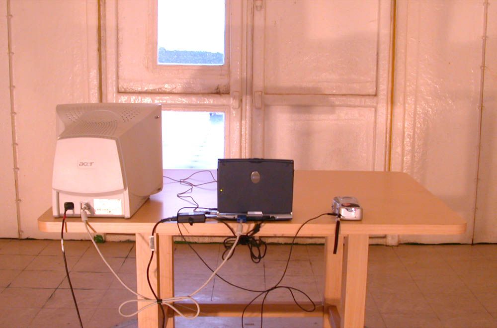
February 12, 2003 RE: Winston NeWeb FCC ID: NKRUSB400 Dear Mr. William, Here are our answers. I have a few comments on this Application. 1.) In the future, please segregate photographs into External and Internal exhibits. A: I thought I have segregated them, EUT 1 as External, EUT 3 & 4 as Internal. Or there is some errors while uploading. I will pay more attention next project. 2.) Although there are two oscillators listed on the block diagram, the diagram seems to not comply with the provisions of 2.1033(a)(5) where the signal path and frequency shall be listed at each block. Please review. A: I updated the block diagram, refer to the uploaded file “USB-400 Block Diagram-updated” 3.) Two manuals were uploaded. Which one should be used for review? I examined the most recent upload according to the date the files was created on our server. That one has references to 20cm separation distance between the user and device. This is not appropriate when a SAR report is presented. A: The two manuals are the same. I updated the manual, refer to the uploaded file “5B USB- 400 manual_update” 4.) The Schematics reference an “Optional Populated” section. This is not appropriate. Only testing performed with and without the optional components could be accepted by the Commission for filing under a single FCC ID, or filing as a fully populated device only. A: I updated the Schematics, refer to the uploaded file “USB- Schematics -updated” 5.) The SAR report in Section 2.1 references an RF Pout of 87.09mW, but later in Section 3 references 30.7mW. Which is correct? Please review and correct as needed. A: updated as uploaded file “SA920116R05- REPORT & ABCD-update’ (answered from ADT). 6.) In the SAR report, I am concerned with the interference of the lid in Mode 1. Please demonstrate this is the “worst case” position. In other words, please provide evidence that Mode 1 with the LCD lid of notebook computer perpendicular to phantom is not “worst case” relative to LCD lid parallel to phantom. A: the Mode 1 is the worst case then I have confimed the LCD lip of the notebook.The worst case position is the LCD lip parallel to the phantom.Please see the attachement documents are the LCD lip perpendicular to phantom position.The SAR values are smaller than the mode 1position.So I think that the mode 1postiton is the worst case. (answered from ADT). (See file under test report exhibit type: USB-400 mode 4 ch01.pdf; USB-400 mode 4 ch06.pdf; USB-400 mode 4 ch11.pdf) 7.) Although listed elsewhere in the SAR report, it would be helpful to identify the test platform by make and model on each “Mode” photograph. A: We will improve next project 8.) The Mode Two plots in the SAR report appear strange – especially when using the scale supplied on the right hand side of each plot. Are you showing the highest SAR occurred in fields around the EUT, and not centered on the EUT? Please confirm. A: I have confirmed the EUT postiton and I adjusted the coarse area. That area is larger than the first coarse area, and the report have been revised (answered from ADT). updated as uploaded file “SA920116R05- REPORT & ABCD-update’ 9.) The Test Setup photos are difficult to use. Can you please supply a close up showing where the EUT was positioned in the setup? A: I have captured one set of close-up photos, both inserted in the test report and segregately uploaded under test set-up photo exhibit type. 10.) The Test Report does not provide any graphical presentations (plots) for any of the 15.247 parameters. This will not be acceptable. Please review and supply at minimum Occupied Bandwidth, Spectral Power Density, Band Edge (preferably both radiated and conducted), and 6dB Bandwidth. A plot of the Powerline Conducted Emissions 15.207 is also preferred. A: I have revised the test report, refer to the uploaded file “03LR001FC-updated” 11.) Please show how label identified in Appendix 9 of Test Report will be affixed to EUT. This does not seem to match the Label information provided in the Label and Location exhibit to AmericanTCB. A: I updated the 9.1 Appendix A, refer to the uploaded file “03LR001FC-updated ” Any insufficiency, please feel free to contact me through E-MAIL. Thanks for your help. Daphne Liu 2003/02/12
Cover Letter(s)
Wistron Neweb Corporation No. 10-1, Li-hsin Road 1, Science-based Industrial Park,Hsinchu 300, Taiwan, R. O. C. 886-3-666-7799 886-3-666-1654 Request for Confidentiality Date: Jan. 29, 2003 American Telecommunications Certification Body, Inc. 6731 Whittier Avenue Suite C110 McLean, VA 22101 RE: Certification Application FCC ID: NKRUSB400 Please be advised that the following information is to be held confidential on behalf of Wistron NeWeb Corporation : Block Diagram Schematics Antenna Spec Technical Spec The application contains technical information which Wistron NeWeb Corporation deems to be trade secrets and proprietary. If made public, the information might be used to the disadvantage of the applicant in the market place. Thank you for your attention to this matter. Sincerely, ________________ Eric Liu / Sr. Manager Engineer Wistron NeWeb Corporation
Operational Description
Applicant: Wistron NeWeb Corporation Manufacturer: Wistron NeWeb Corporation Product Name 802.11b WLAN USB Adapter Brand Name Wistron NeWeb Model Name USB-400 Country to be certified: None Items Contents 1. Modulation type Direct Sequence Spread Spectrum: 2. Procedure to modulation off By test UT, CR12 from 0 to 18 3. Number of channels 11 channels for FCC;13 channels for CE; 14 channels for TELEC 4. Carrier frequency of each channel 2412, 2417, 2422, 2427, 2432, 2437, 2442, 2447, 2452, 2457,2462, 2467& 2472 MHz 5. Bandwidth of each channel 14 MHz for 90 % power 6. L.O. frequency of receiver 2*Channel frequency 7. Transmitter or Transceiver * Transceiver 8. Power Rating (DC/AC, Volt rating) 5Vdc/250mA Max 9. Maximum output power to Antenna 15 dBm+3dBc 10. Duty Cycle 100% test mode 11. Basic function of product Wireless data communication 12. I/O Port or data cable if any USB 13. Antenna Type and Connector Type Embedded meander IFA antenna 14. Operation temperature range 0 o C ~ 60 o C Note: Please attached more documents needed for the comprehension of product’s specification. Provided by : ___________________________ (signature with contact information)
RF Exposure Info
FCC ID: NKRUSB400 Report No.: SA920116R051Issued: Jan. 24, 2003 SAR TEST REPORT REPORT NO.: SA920116R05 MODEL NO.: USB-400 RECEIVED: Jan. 15, 2003 TESTED: Jan. 22, 2003 APPLICANT: Wistron NeWeb Corp. ADDRESS: No. 10-1, Li-hsin Road I, Science-based Industrial Park Hsinchu 300, Taiwan, R.O.C. ISSUED BY: Advance Data Technology Corporation LAB LOCATION: 47 14th Lin, Chiapau Tsun, Linko, Taipei, Taiwan, R.O.C. This test report consists of 15 pages in total except Appendix. It may be duplicated completely for legal use with the approval of the applicant. It should not be reproduced except in full, without the written approval of our laboratory. The client should not use it to claim product endorsement by CNLA, NVLAP or any government agencies. The test results in the report only apply to the tested sample. FCC ID: NKRUSB400 Report No.: SA920116R052Issued: Jan. 24, 2003 Table of Contents 1.CERTIFICATION.....................................................................................3 2.GENERAL INFORMATION.......................................................................4 2.1GENERAL DESCRIPTION OF EUT..........................................................4 2.2GENERAL DESCRIPTION OF APPLIED STANDARDS.............................4 2.3GENERAL INOFRMATION OF THE TEST SYSTEM.................................5 3.DESCRIPTION OF TEST MODES AND CONFIGURATIONS.....................7 4.DESCRIPTION OF SUPPORT UNITS......................................................8 5.TEST RESULTS......................................................................................9 5.1TEST PROCEDURES..............................................................................9 5.2MEASURED SAR RESULT......................................................................9 5.3SAR LIMITS..........................................................................................10 5.4EUT CONDUCTED POWER VARIATION................................................10 5.5TISSUE..................................................................................................11 5.6TEST EQUIPMENT FOR TISSUE PROPERTY........................................11 6.SYSTEM VALIDATION...........................................................................12 7.MEASUREMENT UNCERTAINTIES.......................................................13 8.INFORMATION ON THE TESTING LABORATORIES..............................15 APPENDIX A: TEST CONFIGURATIONS AND TEST DATA APPENDIX B: ADT SAR MEASUREMENT SYSTEM APPENDIX C: PHOTOGRAPHS OF SYSTEM VALIDATION APPENDIX D: SYSTEM CERTIFICATE & CALIBRATION FCC ID: NKRUSB400 Report No.: SA920116R053Issued: Jan. 24, 2003 1. CERTIFICATION PRODUCT : 802.11b WLAN USB Adapter MODEL NO. : USB-400 BRAND : Wistron NeWeb APPLICANT : Wistron NeWeb Corp. STANDARDS : 47 CFR Part 2 (Section 2.1093), FCC OET Bulletin 65, Supplement C (01-01), RSS-102 We, Advance Data Technology Corporation, hereby certify that one sample of the designation has been tested in our facility on 22 nd Jan. 2003. The test record, data evaluation and Equipment Under Test (EUT) configurations represented herein are true and accurate accounts for the measurements of the sample's EMC characteristics under the conditions herein specified. FCC ID: NKRUSB400 Report No.: SA920116R054Issued: Jan. 24, 2003 2. GENERAL INFORMATION 2.1 GENERAL DESCRIPTION OF EUT PRODUCT 802.11b WLAN USB Adapter MODEL NO. USB-400 POWER SUPPLY 5VDC powered by host MODULATION TYPE BPSK, QPSK, CCK (DSSS) TRANSFER RATE 1/2/5.5/11Mbps FREQUENCY RANGE 2412MHz ~ 2462MHz NUMBER OF CHANNEL 11 CONDUCTED OUTPUT POWER 30.7 mW ANTENNA TYPE Printed Inverted-F Antenna PEAK SAR 0.042 W/kg DATA CABLE NA I/O PORTS USB port ASSOCIATED DEVICES NA 2.2 GENERAL DESCRIPTION OF APPLIED STANDARDS According to the specifications of the manufacturer, this product must comply with the requirements of the following standards: FCC 47 CFR Part 2 (2.1093) FCC OET Bulletin 65, Supplement C (01- 01) RSS-102 All tests have been performed and recorded as per the above standards. FCC ID: NKRUSB400 Report No.: SA920116R055Issued: Jan. 24, 2003 2.3 GENERAL INOFRMATION OF THE TEST SYSTEM ET3DV6 ISOTROPIC E-FIELD PROBE Construction Symmetrical design with triangular core. Built-in optical fiber for surface detection system. Built-in shielding against static charges. PEEK enclosure material (resistant to organic solvents, e.g., glycolether). CalibrationBasic Broad Band Calibration in air: 10-2500 MHz Conversion Factors (CF) for HSL 900 and HSL 1800 CF-Calibration for other liquids and frequencies upon request Frequency10 MHz to 3 GHz; Linearity: ± 0.2 dB (30 MHz to 3 GHz) Directivity ± 0.2 dB in HSL (rotation around probe axis) ± 0.4 dB in HSL (rotation normal to probe axis) Dynamic Range5 μW/g to > 100 mW/g; Linearity: ± 0.2 dB Optical Surface Detection± 0.2 mm repeatability in air and clear liquids over diffuse reflecting surfaces DimensionsOverall length: 330 mm (Tip Length: 16 mm) Tip diameter: 6.8 mm (Body diameter: 12 mm) Distance from probe tip to dipole centers: 2.7 mm ApplicationGeneral dosimetric measurements up to 3 GHz Compliance tests of mobile phones Fast automatic scanning in arbitrary phantoms (ET3DV6) FCC ID: NKRUSB400 Report No.: SA920116R056Issued: Jan. 24, 2003 TWIN SAM V4.0 Construction The shell corresponds to the specifications of the Specific Anthropomorphic Mannequin (SAM) phantom defined in IEEE 1528-200X, CENELEC 50361 and IEC 62209. It enables the dosimetric evaluation of left and right hand phone usage as well as body mounted usage at the flat phantom region. A cover prevents evaporation of the liquid. Reference markings on the phantom allow the complete setup of all predefined phantom positions and measurement grids by manually teaching three points with the robot. Shell Thickness2 ± 0.2 mm Filling VolumeApprox. 25 liters Dimensions Height: 810 mm; Length: 1000 mm; Width: 500 mm SYSTEM VALIDATION KITS: D900V2 – D2450V2 Construction Symmetrical dipole with l/4 balun Enables measure…
Text truncated - open the document above for the full version.
RF Exposure Info
Wireless USB Adapter Mode 4 Separation distance : 0mm (Laptop PC to Phantom) Air temperature : 22 degrees centigrade ; Liquid temperature : 21.5 degrees centigrade SAM Phantom; Flat Section; Position: (90°,90°); Antenna type : Embeded PIFA Antenna Modulation type : DSSS Probe: ET3DV6 - SN1687; ConvF(4.40,4.40,4.40); Crest factor: 1.0 Test Frequency : 2412 MHz Liquid parameters : Body 2412 MHz σ = 1.93 mho/m ε r = 52.8 ρ = 1.00 g/cm 3 Coarse : Dx = 20.0, Dy = 20.0, Dz = 10.0 Cube 5x5x7: SAR (1g): 0.0462 mW/g, SAR (10g): 0.0238 mW/g, (Worst-case extrapolation) Powerdrift: 0.02 dB SAR Tot [mW/g] 9.60E-3 1.92E-2 2.88E-2 3.84E-2 4.80E-2 5.76E-2 6.72E-2 7.68E-2 8.64E-2 9.60E-2 02/07/03 ADVANCE DATA TECHNOLOGY CORPORATION
RF Exposure Info
Wireless USB Adapter Mode 4 Separation distance : 0mm (Laptop PC to Phantom) Air temperature : 22 degrees centigrade ; Liquid temperature : 21.5 degrees centigrade SAM Phantom; Flat Section; Position: (90°,90°); Antenna type : Embeded PIFA Antenna Modulation type : DSSS Probe: ET3DV6 - SN1687; ConvF(4.40,4.40,4.40); Crest factor: 1.0 Test Frequency : 2437 MHz Liquid parameters : Body 2437 MHz σ = 1.99 mho/m ε r = 52.6 ρ = 1.00 g/cm 3 Coarse : Dx = 20.0, Dy = 20.0, Dz = 10.0 Cube 5x5x7: SAR (1g): 0.0567 mW/g, SAR (10g): 0.0297 mW/g, (Worst-case extrapolation) Powerdrift: 0.05 dB SAR Tot [mW/g] 6.30E-3 1.26E-2 1.89E-2 2.52E-2 3.15E-2 3.78E-2 4.41E-2 5.04E-2 5.67E-2 6.30E-2 02/07/03 ADVANCE DATA TECHNOLOGY CORPORATION
RF Exposure Info
Wireless USB Adapter Mode 4 Separation distance : 0mm (Laptop PC to Phantom) Air temperature : 22 degrees centigrade ; Liquid temperature : 21.5 degrees centigrade SAM Phantom; Flat Section; Position: (90°,90°); Antenna type : Embeded PIFA Antenna Modulation type : DSSS Probe: ET3DV6 - SN1687; ConvF(4.40,4.40,4.40); Crest factor: 1.0 Test Frequency : 2462 MHz Liquid parameters : Body 2462 MHz σ = 1.90 mho/m ε r = 52.5 ρ = 1.00 g/cm 3 Coarse : Dx = 20.0, Dy = 20.0, Dz = 10.0 Cube 5x5x7: SAR (1g): 0.0450 mW/g, SAR (10g): 0.0236 mW/g, (Worst-case extrapolation) Powerdrift: 0.02 dB SAR Tot [mW/g] 5.00E-3 1.00E-2 1.50E-2 2.00E-2 2.50E-2 3.00E-2 3.50E-2 4.00E-2 4.50E-2 5.00E-2 02/07/03 ADVANCE DATA TECHNOLOGY CORPORATION
Test Report
Report Number: ISL-03LR001FC Test Date: 2003/01/21 NVLAP Lab. Code: 200234-0; VCCI: R-1435, C-1440; NEMKO Aut. No: ELA 113; BSMI Lab. Code: SL2-IN-E-0013 Test Report FOR FCC Part 15 Subpart B & C of 802.11b WLAN USB Adapter Model USB-400 (Brand: Wistron NeWeb) Applied by: Wistron NeWeb Corporation No. 10-1, Li-hsin Road I, Science-based Inductrial Park Hsinchu 300, Taiwan, R. O. C. Test Performed by: (NVLAP Lab. Code: 200234-0) International Standards Laboratory No. 120, Lane 180, San Ho Tsuen, Hsin Ho Rd. Lung-Tan Hsiang, Tao Yuan County 325 Taiwan, R.O.C. Tel:(03)407-1718 Fax:(03)407-1738 FCC ID: NKRUSB400 International Standards Laboratory Report Number: ISL-03LR001FC NVLAP Lab. Code: 200234-0; VCCI: R-1435, C-1440; NEMKO Aut. No: ELA 113; BSMI Lab. Code: SL2-IN-E-0013 -i- Contents of Report 1. . General...............................................................................................3 1.1 Certification of Accuracy of Test Data.............................................................................3 1.2 Description of Equipment Under Test (EUT)...................................................................4 1.3 Test Standards and Procedure........................................................................................5 1.4 Frequency and Channel...................................................................................................5 1.5 General Test Conditions..................................................................................................5 2. Powerline Conducted Emissions [Section 15.207]...........................6 2.1 Configuration and Procedure...........................................................................................6 2.1.1 EUT Configuration.........................................................................................................................................6 2.1.2 Test Procedure................................................................................................................................................6 2.1.3 EMI Receiver/Spectrum Analyzer Configuration (for the frequencies tested).....................................6 2.2 Test Data:.......................................................................................................................7 3. Bandwidth for DSSS [Section 15.247 (a)(2)]....................................9 3.1 Test Procedure...................................................................................................................9 3.2 Test Setup..................................................................................................................................................................9 4. DSSS Maximum Peak Output Power [Section 15.247 (b)(1)].......13 4.1 Test Procedure.................................................................................................................13 4.2 Test Setup.................................................................................................................................................................13 5. RF Exposure Measurement [Section 15.247(b)(4) & 1.1307(b)(1) MPE ].........................................................................................................14 Referto SAR Test Report..........................................................................14 6. Radiated Emission Measurement [Section [15.247(c)(4)].............15 6.1 EUT Configuration........................................................................................................15 6.2 Test Procedure.............................................................................................................15 6.3 EMI Receiver/Spectrum Analyzer Configuration (for the frequencies tested)...................15 6.4 Test Data:.....................................................................................................................16 7. DSSS Peak Power Spectral Density [Section 15.247(d) ]...............22 7.1 Test Procedure.............................................................................................................22 7.2 Test Setup....................................................................................................................22 7.3 Test Data:.....................................................................................................................22 8. Band Edge Measurement...................................................................26 8.1 Test Procedure (Conducted).........................................................................................26 8.2 Test Setup (Conducted)................................................................................................26 8.3 Test Data:.....................................................................................................................26 8.4 Test Procedure (Radiated)............................................................................................29 8.5 Test Setup (Radiated)...................................................................................................29 8.6 Test Data:.....................................................................................................................29 FCC ID: NKRUSB400 International Standards Laboratory Report Number: ISL-03LR001FC NVLAP Lab. Code: 200234-0; VCCI: R-1435, C-1440; NEMKO Aut. No: ELA 113; BSMI Lab. Code: SL2-IN-E-0013 -ii- 9. Appendix............................................................................................32 9.1 Appendix A: Warning Labels........................................................................................32 9.2 Appendix B: Measurement Procedure for Powerline Conducted Emissions....................33 9.3 Appendix C: Test Procedure for Radiated Emissions.....................................................34 9.4 Appendix D: Test Equipment.........................................................................................35 9.4.…
Text truncated - open the document above for the full version.
Contact Information
Applicant
William Su(Senior Director / System Engineering dept.)
Technical Contact
International Standards LaboratoryDaphne Liu
[email protected]+886 3 407 1718
No. 65, Ku Dai Keng Street · Hsichih · Taiwan
Test Firm
International Standards LaboratoryDavid Wu
Technical Specifications
| # | Rule Parts | Frequency Range | Power Output |
|---|---|---|---|
| 1 | 15C | 2.41 GHz - 2.46 GHz | 31.00 mW |
Other Applications from Wistron NeWeb Corporation
NKR-ATTCGW453
Aug 25, 2026Enterprise product
Equipment Class
NII - Unlicensed National Information Infrastructure TXNKR-LS06B
Aug 24, 2026Touchscreen
Equipment Class
NII - Unlicensed National Information Infrastructure TXNKR-DWSZW
Aug 10, 2026Door/Window Sensor
Equipment Class
DXX - Part 15 Low Power Communication Device TransmitterNKR-TELE2
Jun 26, 2026TELE2
Equipment Class
NII - Unlicensed National Information Infrastructure TXNKR-VMC-SA525MAX
Jun 05, 2026NAD (Network Access Device)
Equipment Class
CXX - Communications Rcvr for use w/ licensed Tx and CBs