NKRWLANWARPLINKADirect Sequence Spread Spectrum Transmitter
Wistron NeWeb Corporation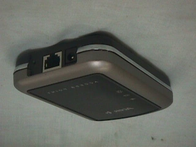
Click to zoom
Application Details
- Equipment Class
- DSS - Part 15 Spread Spectrum Transmitter
- Date of Grant
- Jan 11, 2001
- Application Purpose
- Original Equipment
- Date of Application
- Jan 11, 2001
- Equipment Note
- Direct Sequence Spread Spectrum Transmitter
- Frequency Range
- 2412.00000000 - 2462.00000000
- Company
- Wistron NeWeb Corporation
- Country
- Taiwan
Documents & Files
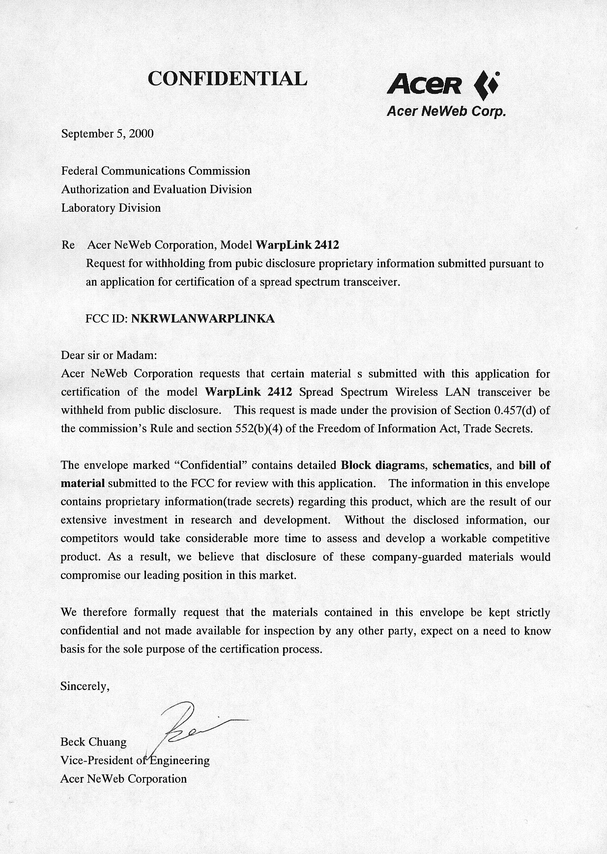
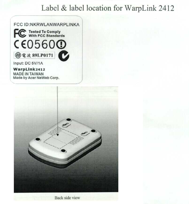
Document Text
Text extracted from the exhibit documents filed with the FCC. Open a document above to read the original.
Users Manual
1 Your Installation Guide to Access Point WarpLink 2412 Version 2.0 – January 2001 - 2 Copyright Statement No part of this publication may be reproduced, stored in a retrieval system, or transmitted in any form or by any means, whether electronic, mechanical, photocopying, recording or otherwise without the prior writing of the publisher. Windows 95/98 and Windows 2000 are trademarks of Microsoft Corp. Pentium is trademark of Intel. All copyright reserved. 3 Table of Contents Table of Contents 3 Regulatory information 5 1. Welcome 6 1.1 Advantages for Using Wireless Network 6 1.2 About Access Point 7 1.3 Verifying kit contents 7 1.4 Wireless Adapter 7 1.5 System Interoperatability 7 2. Step by Step Installation Guide 8 2.1 Install Access Point 8 2.2 Install APManager to your computer 10 3. Guide to APManager Software 12 3.1 About APManager 12 3.2 APManager Features 12 3.3 APManager Main Window 13 4. Using APManager 15 4.1 Managing WLANs 16 4.2 Managing Access Points 18 4.3 Access Point Propertie Tab 19 4.4 Network Settings Dialog 20 4.5 Searching for Access Points 21 4.6 Manually programming IP addresses 22 4.7 Updating Access Point Settings 23 4.8 More about Cells 24 4.9 Compatibility 24 5. Managing Security 25 5.1 WLAN Security Properties Tab 26 5.2 Managing Access Control 27 5.3 IEEE 802.11b WEP Security 28 4 6. Quick Start to Wireless Networking 29 7. Build From Network Wizard 30 7.1 Access Point Settings 31 7.2 Commit to Network 32 7.3 Network Properties 33 7.4 Network Security 34 7.5 Search Network 35 7.6 Confirm Clear Document 36 8. Glossary 36 9. Technical Specifications 37 5 Regulatory Information The manufacturer is not responsible for any radio or television interference caused by unauthorized modification of this device or the substitution or attachment of connecting cables and equipment other than specified. The correction of interference caused by such unauthorized modification, substitution or attachment will be the responsibility of the user. Built-in antennas, whether installed indoors or out, should be installed only by experienced antenna installation professionals who are familiar with local building and safety codes and, wherever applicable, are licensed by the appropriate government regulatory authorities. USA – Federal Communications Commission (FCC) This equipment has been tested and found to comply with the limits for Class B Digital Devices, pursuant to Part 15 of the FCC Rules. These limits are designed to provide reasonable protection against harmful interference in a residential installation. This equipment generates, uses and can radiate radio frequency energy and, if not installed and used in accordance with the instruction, may cause harmful interference to radio communications, However, there is no guarantee that interference will not occur in a particular installation. If this equipment does cause harmful interference to radio or television reception, which can be determined by turning the equipment off and on, the user is encouraged to try to correct the interference by one or more of the following measures: - Reorient or relocate the receiving antenna - Increase the separation between the equipment and the receiver - Connect the equipment into an outlet on a circuit different from that to - which the receiver is connected. - Consult the dealer or an experienced radio/TV technician for help. CAUTION: To comply with FCC RF exposure compliance requirements, a separation distance of at least 2.5cm must be maintained between the antenna of this device and all persons." Canada – Industry Canada (IC) This class B digital apparatus meets all requirements of the Canadian Interference Causing Equipment Regulations. EU Declaration of Conformity (Europe) Access Point conforms to the specifications listed below, following the provisions of the Low Voltage Directive 73/23/EEC and the EMC Directive 89/336/EEC Safety EN60950/IEC950 EMC EN55022/CISPR22 Class B EN50082-1 EN61000-3-2/EN61000-3-3 6 1. Welcome Thank you for purchasing Access Point! Access Point is easy to install and easy to operate, in no time you can have your own wireless network. This guide will lead you through the installation process in detail. It describes most common configurations and a quick start set-up on page 29. You need to have a basic knowledge of installation procedures for network operating systems under Microsoft Windows 95 (or up) and Windows NT. 1.1 Advantages for Using Wireless Network Advantages for Using a Wireless Network: - Hard to wire areas: Access Point provides access to network services in areas otherwise hard or expensive to wire, such as historic buildings with asbestos and classrooms. - Flexible workgroups: Lower total cost of ownership for workspaces that are frequently reconfigured. - Networked conference rooms: user can access the network as they move from meeting to meeting, getting up to date access to information and the ability to communicate decision while ‘on the go’ - Ad hoc networking: on site consultants and small workgroups increase productivity with quick network setup and collaboration software - Branch office networking: provides an easy to install, use and maintain network for a remote or sales office - Campus-wide network mobility: roaming capabilities allow enterprise to set up easy to use wireless networks that cover the entire campus transparently. 7 1.2 About Access Point The Access Point is a modular unit with an integrated Ethernet interface that enables you to use your Access Point with your adaptors. The Antennas are built-in which creates further wireless atmosphere and a cleaner look. The Access Point is a wired to wireless bridge that you can use to connect wireless cells 1 to one another or to a wired (Ethernet) Local Area Network. The Access Point can serve mobile wireless clients roaming between various locations within network premises. 1.3 Verifying Kit Contents The kit you have received should contain the following items: - ‘Your Install…
Text truncated - open the document above for the full version.
Internal Photos
FCC ID: NKRWLANWARPLINKA FCC ID: NKRWLANWARPLINKA FCC ID: NKRWLANWARPLINKA FCC ID: NKRWLANWARPLINKA
Operational Description
Brief of Access Point’s Operation Theorem Introduction: The IEEE 802.11 specification is a wireless LAN standard developed by IEEE (Institute of Electrical and Electronic Engineering) committee in order to specify an “over the air” interface between a wireless client and a base station or Access Point, as well as among wireless clients. Two network topologies are defined: - Infrastructure is a kind of network architecture for providing communication between wireless clients and wired network resources via an Access Point (AP). AP is a device that coexists IEEE 802.3 (Ethernet) and IEEE 802.11 (wireless LAN) architectures. The coverage area of an infrastructure wireless LAN is defined by its AP and associated wireless clients, and together all the devices from a Basic Service Set (BSS). When an AP is present within a BSS, all transmissions only between clients and AP. Clients communicate with AP directly and AP then determines where to send these frames: to another clients in the BSS or to wired network terminals. In other words, all beacons are used for synchronization are transmitted by AP in an infrastructure wireless LAN. - Ad-Hoc network is an architecture that is used to support mutual communication among wireless clients without access point and independents from other LANs. In order to compatible with different upper layers, the IEEE 802.11 specification is like the IEEE 802.3 Ethernet and 802.5 Token Ring standards addresses both the Physical (PHY) and Media Access Control (MAC) layers. Physical Layer (PHY): An AP that is a bridge between a wireless LAN and the wired network has two physical layers: IEEE 802.3 (Ethernet) PHY and IEEE 802.11 (wireless LAN) PHY. Ethernet that is a popular and used widely network standard almost follows IEEE 802.3 standard. We will not mention to 802.3 PHY detail. On the other hand, IEEE 802.11 standard provides three physical characteristics for wireless local area networks: Infrared (IR), Direct Sequence Spread Spectrum (DSSS), and Frequency Hopping Spread Spectrum (FHSS). Actually, only DSSS and FHSS have any significant presence in the market. The DSSS and FHSS PHY options operate in the 2.4 GHz ISM band, a global band primarily set aside for industrial, scientific and medical use, but can be used for operating wireless LAN devices without the need for end-user licenses. The FCC established the operating rules specifically to facilitate shared use of the band for the transmission of data and voice by multiple users in an unlicensed environment. Where DSSS was designed specifically to conform to FCC regulations (FCC 15.247) and it uses DBPSK (1 Mbps) DQPSK (2 Mbps). The draft text of high-speed extension of the IEEE802.11 Standard specifies Complementary Code Keying (CCK) as the modulation scheme for 5.5 and 11Mbps data rates in the 2.4GHz band. FHSS uses 2GFSK and 4GFSK as the modulation scheme for 1 and 2 Mbps individually. Media Access Control Layer (MAC): AP combines 802.3 MAC and 802.11 MAC and provides the service of transformation between different standards’ frame formats. As the description in PHY section, we will not mention to 802.3 MAC detail and only brief the interaction between 802.3 and 802.11 MACs. The IEEE 802.11 MAC layer, supported by an underlying PHY layers, is concerned primarily with rules for accessing the wireless medium. The primarily services provided by the MAC layer of AP are as follow: -Association When a client enters the range of a wireless LAN initially, this service enables the establishment of wireless links between wireless clients and APs in Infrastructure Networks. -Reassociation This takes place in addition to association when a wireless client moves from one Basic Service Set (BSS) to another. Two adjoining Basic Service Sets form an Extended Service Set (ESS) if they are defined by a common ESSID. If a common ESSID is defined, a wireless client can roam from one BSS to another. Although reassociation is specified in 802.11, the mechanism that allows AP-to-AP coordination to handle roaming is not specified. -Authentication Authentication is the process of proving a client identity, and in IEEE 802.11 this process takes place prior to a wireless client associating with an AP. By default, IEEE 802.11 devices operate in an Open System, where essentially any wireless client can associate with an AP without the checking of credentials. True authentication is possible with the use of the IEEE 802.11 option known as Wired Equivalent Privacy or WEP, where a Shared Key is configured into the AP and its wireless clients. Only those devices with a valid Shared Key will be allowed to be associated to the AP. -Data transfer Wireless clients use Distributed Coordination Function (DCF) mode for asynchronous data service and optional Point Coordination Function (PCF) mode for time bounded services . Under DCF mode, each client should follow a Collision Sense Multiple Access with Collision Avoidance (CSMA/CA) algorithm as the media access scheme. AP also has to follow this method under DCF mode. Optional RTS / C TS pair of control frames exchange between transmitter and receiver will reserve the medium for subsequent data access and reduce “Hidden Node” problem. In an infrastructure wireless LAN, AP should deals with two kinds of frame formats (one is 802.3 frame, the other is 802.11 frame) and may transform them. All clients only communicate with AP directly and frames only sent between clients and AP. According to the information of frame header, AP then relays frames to another client in the BSS or wired terminal. AP also relays frames from Ethernet to wireless LAN clients. A frame that is relayed between Ethernet and wireless LAN must be separated into header and Data Frame Body first. According to the information of header, AP’s MAC then transfers one header type to the other header type secondly. AP’s MAC puts Data Frame Body into the new header as a new frame finally, then the new frame will be sent into proper netw…
Text truncated - open the document above for the full version.
Operational Description
Nederlands Meetinstituut Testing and certification of, consultancy and research concerning, electronic and electric appliances, systems, installations and telecommunication systems Nederlands Meetinstituut P.O. Box 15 9822 ZG Niekerk (NL) Smidshornerweg 18 9822 TL Niekerk (NL) Telephone: +31 594 505005 Telefax: +31 594 504804 E-mail: [email protected] NMi B.V. (Chamber of Commerce Haaglanden No. 27228701) Offices: Delft, Bergum, Dordrecht, Niekerk, Utrecht, Tinton Falls NJ (USA), Kawasaki (Japan), Hortolândia SP (Brazil) Subsidiary companies: NMi Certin B.V. (27233418) NMi Van Swinden Laboratorium B.V. (27228703) NMi International B.V. (27239176) Registration number: 10117200R01_FCCreportPage 1 of 44 TEST REPORT OF A 2.4 GHz RLAN ACCESS POINT TRANSCEIVER, BRAND NOWIRESNEEDED, TYPE 11 Mbps WIRELESS LAN ACCESS POINT, IN CONFORMITY WITH FCC PART 15 AND ANSI C63.4-1992 FCC report layout endorsed by the FCC by Public Notice of March 11, 1992. Accredited by Competent body Notified body Designated laboratory Notified test service FCC listed VCCI listed Certification body : : : : : : : : STERLAB accreditation number L029 D.A.R., TTI-P-G.127/96-00 Article 10-2 EMC Directive Article 10-5 EMC Directive Low Voltage Directive Number 0122 TTE Directive TTE Directive Automotive Directive 31040/SIT R 592 and C 507 Electrical Products Safety Regulation Hong Kong Nederlands Meetinstituut FCC ID: Description of EUT: Manufacturer: Brand mark: Type: OGD10410208 2.4 GHz RLAN Access Point transceiver NoWiresNeeded B.V. NoWiresNeeded 11 Mbps WLAN Access Point Registration number: 10117200R01_FCCreportPage 2 of 44 MEASUREMENT/TECHNICAL REPORT NoWiresNeeded B.V. Modelnumber : 11 Mbps WLAN ACCESS POINT FCC ID: OGD10410208 April 28, 2000 This report concerns (check one):Original grant Class II change Equipment type: Direct Sequence Spread Spectrum Transceiver Deferred grant requested per 47 CFR 0.457(d)(1)(ii)? Yesno If yes defer until: NoWiresNeeded, Rembrandtlaan 1a, 3723 BG Bilthoven, The Netherlands agrees to notify the Commission by of the intended date of announcement of the product so that the grant can be issued on that date. Transition Rules Request per 15.37yesno If no, assumed Part 15, Subpart B for unintentional radiators – the new 47 CFR (10-1-90 Edition) provision. Report prepared by:Name: D. S. Sariredjo BSc. E.E. Company name: NMi Certin B.V. Address: Smidshornerweg 18 Telephone number: + 31-59450-50 05 Telefax number: + 31-59450-48 04 Mailing address: P.O. Box 15 City/Place/Postal cd.: 9822 ZG NIEKERK Country: The Netherlands The data taken for this test and report herein was done in accordance with FCC Part 15 and measurement Procedures of ANSI C63.4-1992 and were relevant the procedures as specified in the sheets from the FCC attached to this test report. NMi Certin B.V. at Niekerk, The Netherlands, certifies that the data is accurate and contains a true representation of the emission-profile of the Equipment Under Test (EUT) on the date of the test noted in the test report. I have reviewed the test report and find it to be an accurate description of the test(s) performed and the EUT so tested. Date: April 28, 2000Signature: P.A.J.M. Robben BSc.EE Department EMC and Telecommunication Nederlands Meetinstituut P.O. Box 15 9822 ZG Niekerk (NL) Smidshornerweg 18 9822 TL Niekerk (NL) Telephone: +31 594 505005 Telefax: +31 594 504804 Email: [email protected] Web: http://www.nmicertin.com NMi B.V. (Chamber of Commerce Nr. 27228701) Offices: Delft, Bergum, Dordrecht, Niekerk, Utrecht, Kawasaki (Japan) Salesoffice USA: East Haddam CT Subsidiary companies: NMi Certin B.V. (Nr. 27233418) NMi Van Swinden Laboratorium B.V. (Nr. 27228703) Date Federal Communications Commission May 01, 2000 Attn: To whom it may concern Your reference Office of Engineering and Technology - 445 12TH ST SW Our reference Washington DC 20554 2K0418 U.S.A. Subject Explanatory note Dear Mr./Ms., This letter is being attached as an explanatory note regarding the application for FCC ID: OGD10410208 and contains an example Grant and a copy of our designation as CAB/TCB. The information as contained in this letter is related to our recently obtained designation as CAB/TCB for 47 CFR Part 15 and 18 of the FCC rules. As required by the transitional period, and as defined in the EU-USA MRA, we herewith submit an example of the Grant for FCC ID: OGD10410208, as we would have issued it after the transitional period, in order to have this document reviewed by the FCC. Also included in this letter is a copy of our designation certificate with reference number NLUSAMRARDR001. By submitting this information to this application we want to make use of the transitional (or "confidence building") period for CAB/TCB's as defined in the MRA and as agreed upon in meetings between the US and EU. Yours sincerely, NMi Certin B.V. Pieter A.J.M. Robben, B.Sc.E.E. Manager Department of EMC, Telecommunications and Electrical Safety Bilthoven, April 28, 2000 To: National Radio Type Approval Authority Dear National Radio Type Approval Authority Representative, This letter confirms our agreement that NMi Certin B.V. is authorized as an agent for: NoWiresNeeded B.V. Rembrandtlaan 1a, Bilthoven, 3723 BG, The Netherlands Tel: +31 30 2296060 Fax: +31 30 2296061 Contact person: Remi Blokker Email: [email protected] Web site: www.NWN.com to file and handle applications before National Radio Type Approval Authority on NoWiresNeeded ‘s behalf, and to receive and exchange data between NoWiresNeeded and the National Radio Type Approval Authority in connection with the certification of the following NoWiresNeeded product pursuant to National Radio Type Approval and Certification: Product: Low Power 2.4 GHz RLAN Access Point Transceiver Manufacturer: NoWiresNeeded B.V. Brand/Trade name: NoWiresNeeded Type/Model number: NoWiresNeeded 11 Mbps WLAN Access Point Sincerely, _______________________ Remi Blokker Vice President operations NoWiresNeeded B.V. G r a n t o f e q u i p m e n t a…
Text truncated - open the document above for the full version.
Operational Description
1 File Number4776.1 CAUTION: These devices are sensitive to electrostatic discharge; follow proper IC Handling Procedures. 1-888-INTERSIL or 321-724-7143 |Copyright © Intersil Corporation 1999 PRISM and PRISM logo are trademarks of Intersil Corporation. ADVANCE INFORMATION HFA3861A Direct Sequence Spread Spectrum Baseband Processor The Intersil HFA3861A Direct Sequence Spread Spectrum (DSSS) baseband processor is part of the PRISM® 2.4GHz radio chipset, and contains all the functions necessary for a full or half duplex packet baseband transceiver. The HFA3861A has on-board A/D’s for analog I and Q inputs and outputs, for which the HFA3783 IF QMODEM is recommended. Differential phase shift keying modulation schemes DBPSK and DQPSK, with data scrambling capability, are available along with Complementary Code Keying to provide a variety of data rates. Built-in flexibility allows the HFA3861A to be configured through a general purpose control bus, for a range of applications. Both Receive and Transmit AGC functions with 7-bit AGC control obtain maximum performance in the analog portions of the transceiver. The HFA3861A is housed in a thin plastic quad flat package (TQFP) suitable for PCMCIA board applications. Pinout Features • Complete DSSS Baseband Processor • Processing Gain . . . . . . . . . . . . . . . . . . . . FCC Compliant • Programmable Data Rate. . . . . . . . 1, 2, 5.5, and 11Mbps • Ultra Small Package . . . . . . . . . . . . . . . . . . . . . 10 x 10mm • Single Supply Operation (44MHz Max) . . . . . 2.7V to 3.6V • Modulation Methods . . . . . . . . DBPSK, DQPSK, and CCK • Supports Full or Half Duplex Operations • On-Chip A/D and D/A Converters for I/Q Data (6-Bit, 22MSPS), AGC, and Adaptive Power Control (7-Bit) • Targeted for Multipath Delay Spreads ~50ns • Supports Short Preamble Acquisition • Supports Antenna Diversity Applications • Enterprise WLAN Systems • Systems Targeting IEEE 802.11 Standard • DSSS PCMCIA Wireless Transceiver • Spread Spectrum WLAN RF Modems • TDMA Packet Protocol Radios • Part 15 Compliant Radio Links • Portable PDA/Notebook Computer • Wireless Digital Audio, Video, Multimedia • PCN/Wireless PBX • Wireless Bridges • Antenna Diversity Supported Simplified Block Diagram Ordering Information PART NUMBER TEMP. RANGE ( o C)PACKAGEPKG. NO. HFA3861AIN-40 to 8564 Ld TQFPQ64.10x10 HFA3861AIN96-40 to 85Tape and Reel ™ 64 63 62 61 60 59 58 57 56 55 54 53 52 51 50 49 17 18 19 20 21 22 23 24 25 26 27 28 29 30 31 32 1 2 3 4 5 6 7 8 9 10 11 12 13 14 15 16 48 47 46 45 44 43 42 41 40 39 38 37 36 35 34 33 TEST4 TEST3 TEST2 TEST1 TEST0 GNDd MCLK NC ANT-SEL ANT-SEL RX-RF_AGC V DDD GNDd TX_IF_AGC RX_IF_AGC COMPCAP1 GNDd V DDD SD SCLK R/W CS GNDd V DDD GNDa RX_I+ RX_I- V DDA RX_Q+ RX_Q- GNDa V REF SDIRESETTX_PERX_PECCATX_RDYTXDV DDD GNDdTXCLKMD_RDYRXDRXCLKTEST7TEST6TEST5 V DDA TX_AGC_IN RX-IF_DET GNDa I REF V DDA TX_I+ TX_I- GNDa COMPCAP2 COMPRES2 GNDa TX_Q+ TX_Q- V DDA COMPRES1 6 7 6 6 6 6 7 1 1 ANT_SEL RX_RF_AGC RX_IF_DET THRESH. DETECT IF DAC I ADC Q ADC 44MHz MCLK HFA 3861A BBP TX ALC TX DAC TX ADC I DAC Q DAC MOD I/O DEMOD AGC CTL V REF RX_Q± RX_I± RX_IF_AGC TX_Q± TX_I± TX_IF_AGC TX_AGC_IN DATA I/O Data SheetNovember 1999 2 Typical Application DiagramFor additional information on the PRISM® chip set, call (407) 724-7800 to accessIntersil’ AnswerFAX system. When prompted, key in the four-digit documentnumber (File #) of the data sheets you wish to receive. The four-digit file numbers are shown in the Typical Application Diagram, andcorrespond to the appropriate circuit. TYPICAL TRANSCEIVER APPLICATION CIRCUIT USING THE HFA3861A 676666711 IF DAC I ADC Q ADC 44MHz MCLK HFA3861A BBP TX ALC TX DAC TX ADC I DAC Q DAC MOD I/O DEMOD AGC CTL IF RF ADC RF DAC REF IN LO I/O LO PLL HFA3783 QUAD IF REF IN REF IN RF LO PLL HFA3963 RFPA DIFFERENTIAL SIGNALS REFOUT EXTERNAL MEMORY RADIO DATA INTERFACE RADIO CONTROL PORTS GP SERIAL PORTS WEP ENGINE CPU 16-BIT PIPELINED CONTROL PROCESSOR HOST INTERFACE LOGIC MEMORY ACCESS ARBITER HOSTPC INTERFACE HFA3841 MAC AntSel T/Rsw Σ Σ (FILE# 4776) (FILE# 4633) HFA3683A RF/IFCONV (FILE# 4634) (FILE# TBD) (FILE# 4661) HFA3861A 3 Pin Descriptions NAMEPINTYPE I/ODESCRIPTION V DDA (Analog) 12, 17, 22, 31 PowerDC power supply 2.7V - 3.6V (Not Hard wired Together On Chip). V DDD (Digital) 2, 8, 37, 57PowerDC power supply 2.7 - 3.6V. GNDa (Analog) 9, 15, 20, 25, 28, GroundDC power supply 2.7 - 3.6V, ground (Not Hard wired Together On Chip). GNDd (Digital) 1, 7, 36, 43, 56 GroundDC power supply 2.7 - 3.6V, ground. V REF 16IVoltage reference for A/D’s and D/A’s. I REF 21ICurrent reference for internal ADC and DAC devices. Requires a 12kΩ resistor to ground. RXI , +/- 10/11IAnalog input to the internal 6-bit A/D of the In-phase received data. Balanced differential 10+/11-. RXQ , +/- 13/14IAnalog input to the internal 6-bit A/D of the Quadrature received data. Balanced differential 13+/14-. ANTSEL39OThe antenna select signal changes state as the receiver switches from antenna to antenna during the acquisition process in the antenna diversity mode. This is a complement for ANTSEL (pin 40) for differential drive of antenna switches. ANTSEL40OThe antenna select signal changes state as the receiver switches from antenna to antenna during the acquisition process in the antenna diversity mode. This is a complement for ANTSEL (pin 39) for differential drive of antenna switches. RX_IF_DET19IAnalog input to the receive power A/D converter for AGC control. RX_IF_AGC34OAnalog drive to the IF AGC control. RX_RF_AGC38ODrive to the RF AGC stage attenuator. CMOS digital. TX_AGC_IN18IInput to the transmit power A/D converter for transmit AGC control. TX_IF_AGC35OAnalog drive to the transmit IF power control. TX_PE62IWhen active, the transmitter is configured to be operational, otherwise the transmitter is in standby mode. TX_PE is an input from the external Media Access Controller (MAC) or network processor to the HFA3861A. The rising edge of TX_PE will start the internal tr…
Text truncated - open the document above for the full version.
Operational Description
Report No.: RF90031604 1 Issued: March 26, 2001 PROCESSING GAIN TEST REPORT REPORT NO.: RF90031604 MODEL NO.: WarpLink 2412 RECEIVED: March 16, 2001 TESTED: March 23, 2001 APPLICANT: Acer NeWeb Corporation ADDRESS: 6F, No.110, Sec. 2, Tung Ta Road, Hsinchu, Taiwan, R.O.C. ISSUED BY: Advance Data Technology Corporation LAB LOCATION: 13-1, Lane 19, Wen Shan 3 rd St., Kweishan, Taoyuan Hsien, Taiwan, R.O.C. This test report consists of 29 pages in total. It may be duplicated completely for legal use with the approval of the applicant. It should not be reproduced except in full, without the written approval of our laboratory. The client should not use it to claim product endorsement by NVLAP or any U.S. government agencies. The test results in the report only apply to the tested sample. Accredited Laboratory Report No.: RF90031604 2 Issued: March 26, 2001 Table of Contents 1CERTIFICATION......................................................................................................... 3 2SUMMARY OF TEST RESULTS................................................................................ 4 3GENERAL INFORMATION....................................................................................... 5 3.1GENERAL DESCRIPTION OF EUT .....................................................................................5 3.2DESCRIPTION OF TEST MODES ........................................................................................5 3.3GENERAL DESCRIPTION OF APPLIED STANDARDS ....................................................6 3.4DESCRIPTION OF SUPPORT UNITS...................................................................................6 4TEST PROCEDURES AND RESULTS...................................................................... 7 4.1LIMITS OF PROCESSING GAIN OF A DIRECT SEQUENCE SPREAD SPECTRUM MEASUREMENT ...................................................................................................................7 4.2TEST INSTRUMENTS & SUPPORT UNIT ..........................................................................7 4.3METHOD OF MEASUREMENT ...........................................................................................8 4.4TEST SETUP...........................................................................................................................9 4.5TEST PROCEDURES ...........................................................................................................10 4.6EUT OPERATING CONDITION..........................................................................................10 4.7TEST RESULTS ....................................................................................................................11 5CONCLUSION ........................................................................................................... 29 6.INFORMATION ON THE TESTING LABORATORIES ......................................... 30 Report No.: RF90031604 3 Issued: March 26, 2001 1 CERTIFICATION PRODUCT : 11Mbps Wireless LAN Access Point BRAND NAME : Acer MODEL NO. : WarpLink 2412 APPLICANT : Acer NeWeb Corporation STANDARDS : 47 CFR Part 15, Subpart C (Section 15.247 e2), SITE REGISTERATION NO : 90422 (FCC) IC 3789-5 (Canada IC) We, Advance Data Technology Corporation, hereby certify that one sample WA3001A of the designation has been tested in our facility on March 23, 2001. The test record, data evaluation and Equipment Under Test (EUT) configurations represented herein are true and accurate accounts of the measurements of the sample's EMC characteristics under the conditions herein specified. Report No.: RF90031604 4 Issued: March 26, 2001 2 SUMMARY OF TEST RESULTS The EUT has been tested according to the following specifications: APPLIED STANDARD: 47 CFR Part 15, Subpart C STANDARD PARAGRAPH TEST REQUIREMENTSRESULTREMARK 15.247(e) Processing Gain of Direct Sequence Spread Spectrum System Spec.: min. 10 dB PA S S 20% points lower than 10dB is allowed Report No.: RF90031604 5 Issued: March 26, 2001 3 GENERAL INFORMATION 3.1 GENERAL DESCRIPTION OF EUT PRODUCT 11Mbps Wireless LAN Access Point MODEL NO. WarpLink 2412 POWER SUPPLY 5.0VDC from AC Adapter I/O PORTS NA MODULATION TYPE DSSS BPSK/QPSK/CCK TRANSFER RATE 11/5.5/2/1Mbps FREQUENCY RANGE 2412 ~ 2462MHz NUMBER OF CHANNEL 11 OUTPUT POWER 13dBm CHANNEL SPACING 5MHz DESCRIPTION OF MODELS NA 3.2 DESCRIPTION OF TEST MODES Eleven channels are provided in this EUT. ChannelFrequencyChannelFrequency 12412 MHz72442 MHz 22417 MHz82447 MHz 32422 MHz92452 MHz 42427 MHz102457 MHz 52432 MHz112462 MHz 62437 MHz Note: Since the processing gain of data rate 11Mbps is lower than that of the other data rates, so only 11Mbps is shown in this test report. The EUT was operated with following AC power: Model : UP0111011050A Input Power : 100-250V, 50-60Hz, 0.35A Output Power : 5V, 1.5A Report No.: RF90031604 6 Issued: March 26, 2001 3.3 GENERAL DESCRIPTION OF APPLIED STANDARDS The EUT is a 11Mbps Wireless LAN Access Point, according to the specifications of the manufacturers, it must comply with the requirements of the following standards: FCC CFR 47 Part 15, Subpart C. (15.247 e2) All tests have been performed and recorded as per the above standards. 3.4 DESCRIPTION OF SUPPORT UNITS The EUT has been tested as an independent unit together with other necessary accessories or support units. The following support units or accessories were used to form a representative test configuration during the tests. NoProductBrandModel No.Serial No.I/O Cable 1NOTEBOOKDELL Insprion 5000e TW-012JXN-12961- 0139-2192 Nonshielded Power (1.8m) 2NOTEBOOKDELLPPX99125Nonshielded Power (1.8m) Report No.: RF90031604 7 Issued: March 26, 2001 4 TEST PROCEDURES AND RESULTS 4.1 LIMITS OF PROCESSING GAIN OF A DIRECT SEQUENCE SPREAD SPECTRUM MEASUREMENT Discard the worst 20%, the limit is 10dB. 4.2 TEST INSTRUMENTS & SUPPORT UNIT Description & Manuf…
Text truncated - open the document above for the full version.
Contact Information
Applicant
William Su(Senior Director / System Engineering dept.)
Technical Contact
Intertek Testing Services NA Inc.David Chernomordik
[email protected]650-463-2900
1365 Adams Court · Menlo Park, California · United States
Non-Technical Contact
Acer NeWeb CorporationFelix Chen
408-383-2712
Test Firm
Intertek Testing Services NA Inc.John Quigley
Technical Specifications
| # | Rule Parts | Frequency Range | Power Output |
|---|---|---|---|
| 1 | 15C | 2.41 GHz - 2.46 GHz | 18.60 mW |
Other Applications from Wistron NeWeb Corporation
NKR-ATTCGW453
Aug 25, 2026Enterprise product
Equipment Class
NII - Unlicensed National Information Infrastructure TXNKR-LS06B
Aug 24, 2026Touchscreen
Equipment Class
NII - Unlicensed National Information Infrastructure TXNKR-DWSZW
Aug 10, 2026Door/Window Sensor
Equipment Class
DXX - Part 15 Low Power Communication Device TransmitterNKR-TELE2
Jun 26, 2026TELE2
Equipment Class
NII - Unlicensed National Information Infrastructure TXNKR-VMC-SA525MAX
Jun 05, 2026NAD (Network Access Device)
Equipment Class
CXX - Communications Rcvr for use w/ licensed Tx and CBs