NKRWLANWARPLINKPDirect Sequence Spread Spectrum Transmitter
Wistron NeWeb Corporation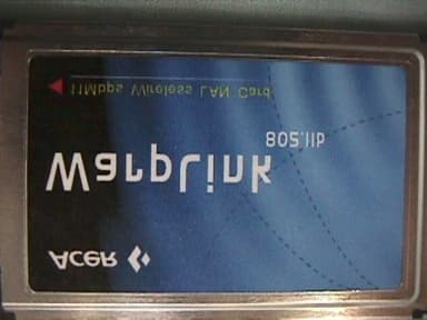
Click to zoom
Application Details
- Equipment Class
- DSS - Part 15 Spread Spectrum Transmitter
- Date of Grant
- Mar 22, 2001
- Application Purpose
- Original Equipment
- Date of Application
- Jan 11, 2001
- Equipment Note
- Direct Sequence Spread Spectrum Transmitter
- Frequency Range
- 2412.00000000 - 2462.00000000
- Company
- Wistron NeWeb Corporation
- Country
- Taiwan
Documents & Files
Document Text
Text extracted from the exhibit documents filed with the FCC. Open a document above to read the original.
Users Manual
1 IEEE 802.11b WLAN PC Card WarpLink 2411 User’s Guide Version:1.08 Please install the Utility/Driver first before inserting the PCMCIA Card. 2 FCC Class B Radio Frequency Interference Statement Note: This equipment has been tested and found to comply with the limits for a Class B digital device, pursuant to Part 15 of FCC Rules. These limits are designed to provide reasonable protection against harmful interference in a residential installation. This equipment generates, uses, and can radiate radio frequency energy and, if not installed and used in accordance with the instructions, may cause harmful interference to radio communications. However, there is no guarantee that interference will not occur in a particular installation. If this equipment does cause harmful interference to radio or television reception, which can be determined by turning the equipment off and on, the user is encouraged to try to correct the interference by one or more of the following measures: 1. Reorient or relocate the receiving antenna. 2. Increase the separation between the equipment and receiver. 3. Connect the equipment into an outlet on a circuit different from that to which the receiver is connected. 4. Consult the dealer or an experienced radio/television technician for help. Notice 1: Changes or modifications not expressly approved by the party responsible for compliance could void the user's authority to operate the equipment. Notice 2: Shielded interface cables, if any, must be used in order to comply with the emission limits. Notice 3: This device complies with part 15 of the FCC Rules. The operation is subject to the following two conditions: (1) This device may not cause harmful interference. (2) This device must accept any interference received, including interference that may cause undesired operation. CAUTION: To comply with FCC RF exposure compliance requirements, a separation distance of at least 2.5cm must be maintained between the antenna of this device and all persons." 3 Table of Contents 1 Introduction...............................................................................................................................1 2 Installation.................................................................................................................................2 2.1 Overview..................................................................................................................................2 2.2 Install the IEEE802.11b WLAN Utility/Driver..............................................................................2 2.3 Install the PCMCIA card..........................................................................................................12 2.4 Utility Startup Configuration......................................................................................................13 2.4.1 Setting..............................................................................................................................13 2.4.2 Wireless LAN Neighborhood.............................................................................................15 2.5 Uninstall the IEEE802.11b WLAN Utility / Driver......................................................................17 3 Application...............................................................................................................................21 3.1 File Sharing in Microsoft Windows 98........................................................................................21 3.2 Printer Sharing in Windows 98..................................................................................................24 3.3 Using the shared folder.............................................................................................................25 3.4 Using the shared network printer...............................................................................................25 4 Troubleshooting.......................................................................................................................26 4.1 Check the Various Properties of the Card..................................................................................26 4.2 Microsoft Networking Checklist................................................................................................26 4.3 Others.....................................................................................................................................29 1 1 Introduction Thank you for purchasing our IEEE802.11b WLAN PCMCIA Card. It will be interoperable among IEEE 802.11b standard compliant products from other manufacturers and allows you to build a wireless LAN. Besides, you can use your PC to connect with an access point wirelessly to share the wired network resource: a. Share your Internet access by using just one connection b. Share printers and other peripheral devices c. Share data and image files between networked PCs d. Play multi-player games IEEE802.11b WLAN can wirelessly transmit and receive data, minimizing the need for wired connections, at a speed of up to eleven megabit per second. With IEEE802.11b WLAN you can locate your PC wherever you want without wires and cables. IEEE802.11b WLAN provide LAN users with great mobility, which are not available under wired network, for real-time information access at anywhere within a reasonable distance. The IEEE802.11b WLAN configuration is easy to change from peer-to-peer networks, suitable for a small number of users, to full infrastructure networks of thousands of users that allow roaming around a broad area. Please read this manual to get familiar with the IEEE802.11b WLAN. This manual contains detailed instructions in operation of this product. Please keep this manual for future reference. Kit Contents The IEEE802.11b WLAN PC Card kit includes the following items: a. A PCMCIA Card b. A CD including:IEEE802.11b WLAN Utility & Driver software, Acrobat Reader3.0 and user manual PDF file. c. …
Text truncated - open the document above for the full version.
External Photos
External Photographs of the WarpLink 2411
Internal Photos
Internal Photographs for WarpLink 2411
Internal Photos
FCC ID: NKRWLANWARPLINKP FCC ID: NKRWLANWARPLINKP FCC ID: NKRWLANWARPLINKP FCC ID: NKRWLANWARPLINKP FCC ID: NKRWLANWARPLINKP FCC ID: NKRWLANWARPLINKP
Operational Description
Nederlands Meetinstituut Testing and certification of, consultancy and research concerning, electronic and electric appliances, systems, installations and telecommunication systems Nederlands Meetinstituut P.O. Box 15 9822 ZG Niekerk (NL) Smidshornerweg 18 9822 TL Niekerk (NL) Telephone: +31 594 505005 Telefax: +31 594 504804 E-mail: [email protected] NMi B.V. (Chamber of Commerce Haaglanden No. 27228701) Offices: Delft, Bergum, Dordrecht, Niekerk, Utrecht, Tinton Falls NJ (USA), Kawasaki (Japan), Hortolândia SP (Brazil) Subsidiary companies: NMi Certin B.V. (27233418) NMi Van Swinden Laboratorium B.V. (27228703) NMi International B.V. (27239176) Registration number: 10117200R01_FCCreportPage 1 of 44 TEST REPORT OF A 2.4 GHz RLAN ACCESS POINT TRANSCEIVER, BRAND NOWIRESNEEDED, TYPE 11 Mbps WIRELESS LAN ACCESS POINT, IN CONFORMITY WITH FCC PART 15 AND ANSI C63.4-1992 FCC report layout endorsed by the FCC by Public Notice of March 11, 1992. Accredited by Competent body Notified body Designated laboratory Notified test service FCC listed VCCI listed Certification body : : : : : : : : STERLAB accreditation number L029 D.A.R., TTI-P-G.127/96-00 Article 10-2 EMC Directive Article 10-5 EMC Directive Low Voltage Directive Number 0122 TTE Directive TTE Directive Automotive Directive 31040/SIT R 592 and C 507 Electrical Products Safety Regulation Hong Kong Nederlands Meetinstituut FCC ID: Description of EUT: Manufacturer: Brand mark: Type: OGD10410208 2.4 GHz RLAN Access Point transceiver NoWiresNeeded B.V. NoWiresNeeded 11 Mbps WLAN Access Point Registration number: 10117200R01_FCCreportPage 2 of 44 MEASUREMENT/TECHNICAL REPORT NoWiresNeeded B.V. Modelnumber : 11 Mbps WLAN ACCESS POINT FCC ID: OGD10410208 April 28, 2000 This report concerns (check one):Original grant Class II change Equipment type: Direct Sequence Spread Spectrum Transceiver Deferred grant requested per 47 CFR 0.457(d)(1)(ii)? Yesno If yes defer until: NoWiresNeeded, Rembrandtlaan 1a, 3723 BG Bilthoven, The Netherlands agrees to notify the Commission by of the intended date of announcement of the product so that the grant can be issued on that date. Transition Rules Request per 15.37yesno If no, assumed Part 15, Subpart B for unintentional radiators – the new 47 CFR (10-1-90 Edition) provision. Report prepared by:Name: D. S. Sariredjo BSc. E.E. Company name: NMi Certin B.V. Address: Smidshornerweg 18 Telephone number: + 31-59450-50 05 Telefax number: + 31-59450-48 04 Mailing address: P.O. Box 15 City/Place/Postal cd.: 9822 ZG NIEKERK Country: The Netherlands The data taken for this test and report herein was done in accordance with FCC Part 15 and measurement Procedures of ANSI C63.4-1992 and were relevant the procedures as specified in the sheets from the FCC attached to this test report. NMi Certin B.V. at Niekerk, The Netherlands, certifies that the data is accurate and contains a true representation of the emission-profile of the Equipment Under Test (EUT) on the date of the test noted in the test report. I have reviewed the test report and find it to be an accurate description of the test(s) performed and the EUT so tested. Date: April 28, 2000Signature: P.A.J.M. Robben BSc.EE Department EMC and Telecommunication Nederlands Meetinstituut P.O. Box 15 9822 ZG Niekerk (NL) Smidshornerweg 18 9822 TL Niekerk (NL) Telephone: +31 594 505005 Telefax: +31 594 504804 Email: [email protected] Web: http://www.nmicertin.com NMi B.V. (Chamber of Commerce Nr. 27228701) Offices: Delft, Bergum, Dordrecht, Niekerk, Utrecht, Kawasaki (Japan) Salesoffice USA: East Haddam CT Subsidiary companies: NMi Certin B.V. (Nr. 27233418) NMi Van Swinden Laboratorium B.V. (Nr. 27228703) Date Federal Communications Commission May 01, 2000 Attn: To whom it may concern Your reference Office of Engineering and Technology - 445 12TH ST SW Our reference Washington DC 20554 2K0418 U.S.A. Subject Explanatory note Dear Mr./Ms., This letter is being attached as an explanatory note regarding the application for FCC ID: OGD10410208 and contains an example Grant and a copy of our designation as CAB/TCB. The information as contained in this letter is related to our recently obtained designation as CAB/TCB for 47 CFR Part 15 and 18 of the FCC rules. As required by the transitional period, and as defined in the EU-USA MRA, we herewith submit an example of the Grant for FCC ID: OGD10410208, as we would have issued it after the transitional period, in order to have this document reviewed by the FCC. Also included in this letter is a copy of our designation certificate with reference number NLUSAMRARDR001. By submitting this information to this application we want to make use of the transitional (or "confidence building") period for CAB/TCB's as defined in the MRA and as agreed upon in meetings between the US and EU. Yours sincerely, NMi Certin B.V. Pieter A.J.M. Robben, B.Sc.E.E. Manager Department of EMC, Telecommunications and Electrical Safety Bilthoven, April 28, 2000 To: National Radio Type Approval Authority Dear National Radio Type Approval Authority Representative, This letter confirms our agreement that NMi Certin B.V. is authorized as an agent for: NoWiresNeeded B.V. Rembrandtlaan 1a, Bilthoven, 3723 BG, The Netherlands Tel: +31 30 2296060 Fax: +31 30 2296061 Contact person: Remi Blokker Email: [email protected] Web site: www.NWN.com to file and handle applications before National Radio Type Approval Authority on NoWiresNeeded ‘s behalf, and to receive and exchange data between NoWiresNeeded and the National Radio Type Approval Authority in connection with the certification of the following NoWiresNeeded product pursuant to National Radio Type Approval and Certification: Product: Low Power 2.4 GHz RLAN Access Point Transceiver Manufacturer: NoWiresNeeded B.V. Brand/Trade name: NoWiresNeeded Type/Model number: NoWiresNeeded 11 Mbps WLAN Access Point Sincerely, _______________________ Remi Blokker Vice President operations NoWiresNeeded B.V. G r a n t o f e q u i p m e n t a…
Text truncated - open the document above for the full version.
Operational Description
1 File Number4776.1 CAUTION: These devices are sensitive to electrostatic discharge; follow proper IC Handling Procedures. 1-888-INTERSIL or 321-724-7143 |Copyright © Intersil Corporation 1999 PRISM and PRISM logo are trademarks of Intersil Corporation. ADVANCE INFORMATION HFA3861A Direct Sequence Spread Spectrum Baseband Processor The Intersil HFA3861A Direct Sequence Spread Spectrum (DSSS) baseband processor is part of the PRISM® 2.4GHz radio chipset, and contains all the functions necessary for a full or half duplex packet baseband transceiver. The HFA3861A has on-board A/D’s for analog I and Q inputs and outputs, for which the HFA3783 IF QMODEM is recommended. Differential phase shift keying modulation schemes DBPSK and DQPSK, with data scrambling capability, are available along with Complementary Code Keying to provide a variety of data rates. Built-in flexibility allows the HFA3861A to be configured through a general purpose control bus, for a range of applications. Both Receive and Transmit AGC functions with 7-bit AGC control obtain maximum performance in the analog portions of the transceiver. The HFA3861A is housed in a thin plastic quad flat package (TQFP) suitable for PCMCIA board applications. Pinout Features • Complete DSSS Baseband Processor • Processing Gain . . . . . . . . . . . . . . . . . . . . FCC Compliant • Programmable Data Rate. . . . . . . . 1, 2, 5.5, and 11Mbps • Ultra Small Package . . . . . . . . . . . . . . . . . . . . . 10 x 10mm • Single Supply Operation (44MHz Max) . . . . . 2.7V to 3.6V • Modulation Methods . . . . . . . . DBPSK, DQPSK, and CCK • Supports Full or Half Duplex Operations • On-Chip A/D and D/A Converters for I/Q Data (6-Bit, 22MSPS), AGC, and Adaptive Power Control (7-Bit) • Targeted for Multipath Delay Spreads ~50ns • Supports Short Preamble Acquisition • Supports Antenna Diversity Applications • Enterprise WLAN Systems • Systems Targeting IEEE 802.11 Standard • DSSS PCMCIA Wireless Transceiver • Spread Spectrum WLAN RF Modems • TDMA Packet Protocol Radios • Part 15 Compliant Radio Links • Portable PDA/Notebook Computer • Wireless Digital Audio, Video, Multimedia • PCN/Wireless PBX • Wireless Bridges • Antenna Diversity Supported Simplified Block Diagram Ordering Information PART NUMBER TEMP. RANGE ( o C)PACKAGEPKG. NO. HFA3861AIN-40 to 8564 Ld TQFPQ64.10x10 HFA3861AIN96-40 to 85Tape and Reel ™ 64 63 62 61 60 59 58 57 56 55 54 53 52 51 50 49 17 18 19 20 21 22 23 24 25 26 27 28 29 30 31 32 1 2 3 4 5 6 7 8 9 10 11 12 13 14 15 16 48 47 46 45 44 43 42 41 40 39 38 37 36 35 34 33 TEST4 TEST3 TEST2 TEST1 TEST0 GNDd MCLK NC ANT-SEL ANT-SEL RX-RF_AGC V DDD GNDd TX_IF_AGC RX_IF_AGC COMPCAP1 GNDd V DDD SD SCLK R/W CS GNDd V DDD GNDa RX_I+ RX_I- V DDA RX_Q+ RX_Q- GNDa V REF SDIRESETTX_PERX_PECCATX_RDYTXDV DDD GNDdTXCLKMD_RDYRXDRXCLKTEST7TEST6TEST5 V DDA TX_AGC_IN RX-IF_DET GNDa I REF V DDA TX_I+ TX_I- GNDa COMPCAP2 COMPRES2 GNDa TX_Q+ TX_Q- V DDA COMPRES1 6 7 6 6 6 6 7 1 1 ANT_SEL RX_RF_AGC RX_IF_DET THRESH. DETECT IF DAC I ADC Q ADC 44MHz MCLK HFA 3861A BBP TX ALC TX DAC TX ADC I DAC Q DAC MOD I/O DEMOD AGC CTL V REF RX_Q± RX_I± RX_IF_AGC TX_Q± TX_I± TX_IF_AGC TX_AGC_IN DATA I/O Data SheetNovember 1999 2 Typical Application DiagramFor additional information on the PRISM® chip set, call (407) 724-7800 to accessIntersil’ AnswerFAX system. When prompted, key in the four-digit documentnumber (File #) of the data sheets you wish to receive. The four-digit file numbers are shown in the Typical Application Diagram, andcorrespond to the appropriate circuit. TYPICAL TRANSCEIVER APPLICATION CIRCUIT USING THE HFA3861A 676666711 IF DAC I ADC Q ADC 44MHz MCLK HFA3861A BBP TX ALC TX DAC TX ADC I DAC Q DAC MOD I/O DEMOD AGC CTL IF RF ADC RF DAC REF IN LO I/O LO PLL HFA3783 QUAD IF REF IN REF IN RF LO PLL HFA3963 RFPA DIFFERENTIAL SIGNALS REFOUT EXTERNAL MEMORY RADIO DATA INTERFACE RADIO CONTROL PORTS GP SERIAL PORTS WEP ENGINE CPU 16-BIT PIPELINED CONTROL PROCESSOR HOST INTERFACE LOGIC MEMORY ACCESS ARBITER HOSTPC INTERFACE HFA3841 MAC AntSel T/Rsw Σ Σ (FILE# 4776) (FILE# 4633) HFA3683A RF/IFCONV (FILE# 4634) (FILE# TBD) (FILE# 4661) HFA3861A 3 Pin Descriptions NAMEPINTYPE I/ODESCRIPTION V DDA (Analog) 12, 17, 22, 31 PowerDC power supply 2.7V - 3.6V (Not Hard wired Together On Chip). V DDD (Digital) 2, 8, 37, 57PowerDC power supply 2.7 - 3.6V. GNDa (Analog) 9, 15, 20, 25, 28, GroundDC power supply 2.7 - 3.6V, ground (Not Hard wired Together On Chip). GNDd (Digital) 1, 7, 36, 43, 56 GroundDC power supply 2.7 - 3.6V, ground. V REF 16IVoltage reference for A/D’s and D/A’s. I REF 21ICurrent reference for internal ADC and DAC devices. Requires a 12kΩ resistor to ground. RXI , +/- 10/11IAnalog input to the internal 6-bit A/D of the In-phase received data. Balanced differential 10+/11-. RXQ , +/- 13/14IAnalog input to the internal 6-bit A/D of the Quadrature received data. Balanced differential 13+/14-. ANTSEL39OThe antenna select signal changes state as the receiver switches from antenna to antenna during the acquisition process in the antenna diversity mode. This is a complement for ANTSEL (pin 40) for differential drive of antenna switches. ANTSEL40OThe antenna select signal changes state as the receiver switches from antenna to antenna during the acquisition process in the antenna diversity mode. This is a complement for ANTSEL (pin 39) for differential drive of antenna switches. RX_IF_DET19IAnalog input to the receive power A/D converter for AGC control. RX_IF_AGC34OAnalog drive to the IF AGC control. RX_RF_AGC38ODrive to the RF AGC stage attenuator. CMOS digital. TX_AGC_IN18IInput to the transmit power A/D converter for transmit AGC control. TX_IF_AGC35OAnalog drive to the transmit IF power control. TX_PE62IWhen active, the transmitter is configured to be operational, otherwise the transmitter is in standby mode. TX_PE is an input from the external Media Access Controller (MAC) or network processor to the HFA3861A. The rising edge of TX_PE will start the internal tr…
Text truncated - open the document above for the full version.
Operational Description
TM 1 File Number4661.2 Microsoft® and Windows® are registered trademarks of Microsoft Corporation. 1-888-INTERSIL or 321-724-7143|Intersil and Design is a trademark of Intersil Corporation.|Copyright © Intersil Corporation 2000 PRISM® is a registered trademark of Intersil Corporation. PRISM logo is a trademark of Intersil Corporation. PRELIMINARY HFA3841 Wireless LAN Medium Access Controller The Intersil HFA3841 Wireless LAN Medium Access Controller is part of the PRISM® Enterprise 2.4GHz WLAN chip set. The HFA3841 directly interfaces with the Intersil HFA386x family of Baseband Processors, offering a complete end-to- end chip set solution for wireless LAN products. Protocol and PHY support are implemented in firmware to allow custom protocol and different PHY transceivers. The HFA3841 is designed to provide maximum performance with minimum power consumption. External pin layout is organized to provide optimal PC board layout to all user interfaces. Firmware implements the full IEEE 802.11 Wireless LAN MAC protocol. It supports BSS and IBSS operation under DCF, and operation under the optional Point Coordination Function (PCF). Low level protocol functions such as RTS/CTS generation and acknowledgement, fragmentation and de-fragmentation, and automatic beacon monitoring are handed without host intervention. Active scanning is performed autonomously once initiated by host command. Host interface command and status handshakes allow concurrent operations from multi-threaded I/O drivers. Additional firmware functions specific to access point applications are also available. Designing wireless protocol systems using the HFA3841 is made easier with the availability of evaluation board, firmware, software device drivers, and complete documentation. Features • IEEE802.11 Standard Data Rates: 1, 2, 5.5 and 11Mbps • Part of the Intersil PRISM Wireless LAN Chip Set • Full Implementation of the MAC Protocol Specified in IEEE Std. 802.11-1999 and the 802.11b Draft Standard • Host Interface Supports Full 16-Bit Implementation of PC Card 95, also ISA PnP with Additional Chip • Host Interface Provides Dual Buffer Access Paths • External Memory Interface Supports up to 4M bytes RAM • Internal Encryption Engine Executes IEEE802.11 WEP • Low Power Operation; 25mA Active, 8mA Doze, <1mA Sleep • Operation at 2.7V to 3.6V Supply • 3V to 5V Tolerant Input/Outputs • 128 Pin LQFP Package Targeted for Type II PC Cards • IEEE802.11 Wireless LAN MAC Protocol Firmware and Microsoft® Windows® Software Drivers Applications • High Data Rate Wireless LAN • PC Card Wireless LAN Adapters • ISA, ISA PnP WLAN Cards • PCI Wireless LAN Cards (Using Ext. Bridge Chip) • Wireless LAN Modules • Wireless LAN Access Points • Wireless Bridge Products • Wireless Point-to-Multipoint Systems Ordering Information PART NUMBER TEMP. RANGE ( o C)PACKAGEPKG. NO. HFA3841CN0 to 70128 Ld LQFPQ128.14x20 HFA3841CN960 to 70Tape and Reel Data SheetJanuary 2000 CAUTION: These devices are sensitive to electrostatic discharge; follow proper IC Handling Procedures. 2 Pinout Simplified Block Diagram 103 66 64 63 62 61 60 59 58 57 56 55 54 53 52 51 50 49 48 47 46 45 44 43 42 41 40 MA8MA7MA6MA5MA3MA2MA4MA9MA17MA16MA15MA14MA12MA11MA10V CC _IO3 V SS _IO3 MA13MA18HD8HD9HD10PL7MOE-RAMCS-NVCS-V CC _IO3 PJ4V SS _IO3 MWEL- MA1MA0 PJ2PJ1PJ3 PK7PK6 V SS _CORE3 V CC _CORE3 PL2PL1PL3 PJ0 PL0 V CC _CORE3 V SS _CORE3 PL5 TCLKIN RESET TXDTXC RXDRXC PJ7 HD6HD7 HCE1- HD5HD4HD3 PJ6PJ5 PL6 V SS _IO3 V CC _IO3 HD2HD1HD0HREG- PK5 7273747576776768697071838485867879808182929394959697878889909198 INDEX 134567891011121314151617181920212223242526272829303132 PK2PK1PK0 HSTSCHG- V SS _CORE3 CLKOUT V CC _CORE3 XTALI XTALO V SS _IO3 PL4 MD15 MD14 MD13 MD12 MD11 MD10 MD9 MD8 V SS _IO3 V CC _CORE3 MD7 MD6 MD5 MD4 MD3 MD2 MD1 MD0 TRST- PK3 PK4 2333435363738 99 100101 102 104 105 106 107 108 109 110 111 112 113 114 115 116 117 118 119 120 121 122 123 124 125 126 127 128 HINPACK- HWAIT- HA0 HA1 HA2 HA3 HA4 HA5 HA6 HA7 HIREQ- V SS _IO3 HWE- HA8 HA9 HIOWR- HIORD- HOE- HCE2- HD15 V CC _IO3 HD14 HD13 HD12 HD11 V CC _IO5 39 65 PRISM RADIO BASEBAND PROCESSOR TXD/RXD CTRL/STATUS SERIAL CONTROL PHY INTERFACE (MDI) SERIAL CONTROL (MMI) PRISM RADIO RF SECTION RADIO AND SYNTH SERIAL CONTROL MICRO- PROGRAMMED MAC ENGINE MEMORY CONTROLLER WEP ENGINE PC CARD HOST INTERFACE ON-CHIP MEMORY 44MHz CLOCK SOURCE DATA ADDRESS SELECT EXTERNAL SRAM AND FLASH MEMORY HOST COMPUTER DATA ADDRESS CONTROL HFA3841 Preliminary - HFA3841 3 HFA3841 Pin Descriptions Host Interface Pins PIN NAMEPIN NUMBERPIN I/O TYPEDESCRIPTION HA0-9106-113, 117, 118 5V tol, CMOS, Input, 50K Pull DownPC Card address input, bits 0 to 9 HCE1-15V tol, CMOS, Input, 50K Pull UpPC Card card select, low byte HCE2-1225V tol, CMOS, Input, 50K Pull UpPC Card card select, high byte HD0-15101-99, 6-2, 96-94, 128-125, 123 5V tol, BiDir, 2mA, 50K Pull DownPC Card data bus, bit 0 to 15 HINPACK-103CMOS Output, 2mAPC Card I/O decode confirmation HIORD-1205V tol, CMOS, Input, 50K Pull UpPC Card I/O space read HIOWR-1195V tol, CMOS, Input, 50K Pull UpPC Card I/O space write HRDY/HIREQ-114CMOS Output, 4mAPC Card interrupt request (I/O mode) Card ready (memory mode) HOE-1215V tol, CMOS, Input, 50K Pull UpPC Card memory attribute space output enable HREG-1025V tol, CMOS, Input, 50K Pull UpPC Card attribute space select HRESET165V tol, CMOS, ST Input, 50K Pull Up Hardware Re- set HSTSCHG-36CMOS Output, 4mAPC Card status change HWAIT-104CMOS Output, 4mAPC Card not ready (force host wait state) HWE-1165V tol, CMOS Input, 50K Pull UpPC Card memory attribute space write enable Memory Interface Pins PIN NAMEPIN NUMBERPIN I/O TYPEDESCRIPTION MA0 MWEH-72CMOS TS Output, 2mAMBUS address bit 0 (byte) for x8 memory High byte write enable for x16 memory MA1-1873-81, 84-92CMOS TS Output, 2mAMBUS address bits 1 to 18 PL443CMOS BiDir, 2mAMBUS address bit 19 PL512CMOS BiDir, 2mA, 50K Pull UpMBUS address bit 20 PL611CMOS BiDir, 2mAMBUS address bit 21 MOE-70CMOS TS Output, 2mAMe…
Text truncated - open the document above for the full version.
Operational Description
Report No.: RF90022613 1 Issued: March 6, 2001 PROCESSING GAIN TEST REPORT REPORT NO.: RF90022613 MODEL NO.: WarpLink 2411 RECEIVED: February 26, 2001 TESTED: March 6, 2001 APPLICANT: Acer NeWeb Corporation ADDRESS: 6F, No.110, Sec. 2, Tung Ta Road, Hsinchu, Taiwan, R.O.C. ISSUED BY: Advance Data Technology Corporation LAB LOCATION: 13-1, Lane 19, Wen Shan 3 rd St., Kweishan, Taoyuan Hsien, Taiwan, R.O.C. This test report consists of 30 pages in total. It may be duplicated completely for legal use with the approval of the applicant. It should not be reproduced except in full, without the written approval of our laboratory. The client should not use it to claim product endorsement by NVLAP or any U.S. government agencies. The test results in the report only apply to the tested sample. Accredited Laboratory Report No.: RF90022613 2 Issued: March 6, 2001 Table of Contents 1CERTIFICATION......................................................................................................... 3 2SUMMARY OF TEST RESULTS................................................................................ 4 3GENERAL INFORMATION....................................................................................... 5 3.1GENERAL DESCRIPTION OF EUT .....................................................................................5 3.2DESCRIPTION OF TEST MODES ........................................................................................5 3.3GENERAL DESCRIPTION OF APPLIED STANDARDS ....................................................6 3.4DESCRIPTION OF SUPPORT UNITS...................................................................................6 4TEST PROCEDURES AND RESULTS...................................................................... 7 4.1LIMITS OF PROCESSING GAIN OF A DIRECT SEQUENCE SPREAD SPECTRUM MEASUREMENT ...................................................................................................................7 4.2TEST INSTRUMENTS & SUPPORT UNIT ..........................................................................7 4.3METHOD OF MEASUREMENT ...........................................................................................8 4.4TEST SETUP...........................................................................................................................9 4.5TEST PROCEDURES ...........................................................................................................10 4.6EUT OPERATING CONDITION..........................................................................................10 4.7TEST RESULTS ....................................................................................................................11 5INFORMATION ON THE TESTING LABORATORIES......................................... 29 A NNEX : P HOTO OF TEST CONFIGURATION Report No.: RF90022613 3 Issued: March 6, 2001 1 CERTIFICATION PRODUCT : 11Mbps Wireless LAN PCMCIA Card BRAND NAME : Acer MODEL NO. : WarpLink 2411 APPLICANT : Acer NeWeb Corporation STANDARDS : 47 CFR Part 15, Subpart C (Section 15.247 e2), SITE REGISTERATION NO : 90422 (FCC) IC 3789-5 (Canada IC) We, Advance Data Technology Corporation, hereby certify that one sample WA3001A of the designation has been tested in our facility on March 6, 2001. The test record, data evaluation and Equipment Under Test (EUT) configurations represented herein are true and accurate accounts of the measurements of the sample's EMC characteristics under the conditions herein specified. Report No.: RF90022613 4 Issued: March 6, 2001 2 SUMMARY OF TEST RESULTS The EUT has been tested according to the following specifications: APPLIED STANDARD: 47 CFR Part 15, Subpart C STANDARD PARAGRAPH TEST REQUIREMENTSRESULTREMARK 15.247(e) Processing Gain of Direct Sequence Spread Spectrum System Spec.: min. 10 dB PA S S 20% points lower than 10dB is allowed Report No.: RF90022613 5 Issued: March 6, 2001 3 GENERAL INFORMATION 3.1 GENERAL DESCRIPTION OF EUT PRODUCT 11Mbps Wireless LAN PCMCIA Card MODEL NO. WarpLink 2411 POWER SUPPLY 3.3VDC DATA CABLE I/O PORTS NA MODULATION TYPE DSSS BPSK/QPSK/CCK TRANSFER RATE 11/5.5/2/1Mbps FREQUENCY RANGE 2412 ~ 2462MHz NUMBER OF CHANNEL 11 ANTENNA TYPE ASSOCIATED DEVICES NA DESCRIPTION BETWEEN MODELS NA 3.2 DESCRIPTION OF TEST MODES Eleven channels are provided in this EUT. ChannelFrequencyChannelFrequency 12412 MHz72442 MHz 22417 MHz82447 MHz 32422 MHz92452 MHz 42427 MHz102457 MHz 52432 MHz112462 MHz 62437 MHz Note: Since the processing gain of data rate 11Mbps is lower than that of the other data rates, so only 11Mbps is shown in this test report. Report No.: RF90022613 6 Issued: March 6, 2001 3.3 GENERAL DESCRIPTION OF APPLIED STANDARDS The EUT is a 11Mbps Wireless LAN PCMCIA Card, according to the specifications of the manufacturers, it must comply with the requirements of the following standards: FCC CFR 47 Part 15, Subpart C. (15.247 e2) All tests have been performed and recorded as per the above standards. 3.4 DESCRIPTION OF SUPPORT UNITS The EUT has been tested as an independent unit together with other necessary accessories or support units. The following support units or accessories were used to form a representative test configuration during the tests. NoProductBrandModel No.Serial No.I/O Cable 1NOTEBOOKDELL Insprion 5000e TW-012JXN-12961- 0139-2192 Nonshielded Power (1.8m) 2NOTEBOOKDELLPPX99125Nonshielded Power (1.8m) Report No.: RF90022613 7 Issued: March 6, 2001 4 TEST PROCEDURES AND RESULTS 4.1 LIMITS OF PROCESSING GAIN OF A DIRECT SEQUENCE SPREAD SPECTRUM MEASUREMENT Discard the worst 20%, the limit is 10dB. 4.2 TEST INSTRUMENTS & SUPPORT UNIT Description & ManufacturerModel No.Serial No. Anritsu Spectrum Analyzer, 9kHz to 30GHz MS2667CM10281 Anritsu Signal Genera…
Text truncated - open the document above for the full version.
Contact Information
Applicant
William Su(Senior Director / System Engineering dept.)
Technical Contact
Intertek Testing Services NA Inc.David Chernomordik
[email protected]650-463-2900
1365 Adams Court · Menlo Park, California · United States
Non-Technical Contact
Acer NeWeb CorporationFelix Chen
408-383-2712
Test Firm
Intertek Testing Services NA Inc.John Quigley
Technical Specifications
| # | Rule Parts | Frequency Range | Power Output |
|---|---|---|---|
| 1 | 15C | 2.41 GHz - 2.46 GHz | 21.90 mW |
Other Applications from Wistron NeWeb Corporation
NKR-ATTCGW453
Aug 25, 2026Enterprise product
Equipment Class
NII - Unlicensed National Information Infrastructure TXNKR-LS06B
Aug 24, 2026Touchscreen
Equipment Class
NII - Unlicensed National Information Infrastructure TXNKR-DWSZW
Aug 10, 2026Door/Window Sensor
Equipment Class
DXX - Part 15 Low Power Communication Device TransmitterNKR-TELE2
Jun 26, 2026TELE2
Equipment Class
NII - Unlicensed National Information Infrastructure TXNKR-VMC-SA525MAX
Jun 05, 2026NAD (Network Access Device)
Equipment Class
CXX - Communications Rcvr for use w/ licensed Tx and CBs