NM5-2458-ALWireless LAN
YDI Wireless
Click to zoom
Application Details
- Equipment Class
- DSS - Part 15 Spread Spectrum Transmitter
- Date of Grant
- Apr 11, 2002
- Application Purpose
- Original Equipment
- Date of Application
- Apr 11, 2002
- Equipment Note
- Wireless LAN
- Frequency Range
- 5740.00000000 - 5811.00000000
- Company
- YDI Wireless
- Country
- United States
Documents & Files
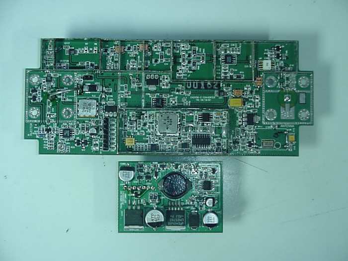
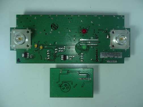
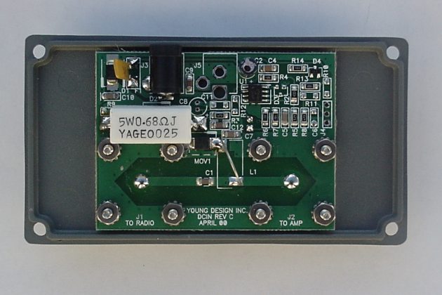
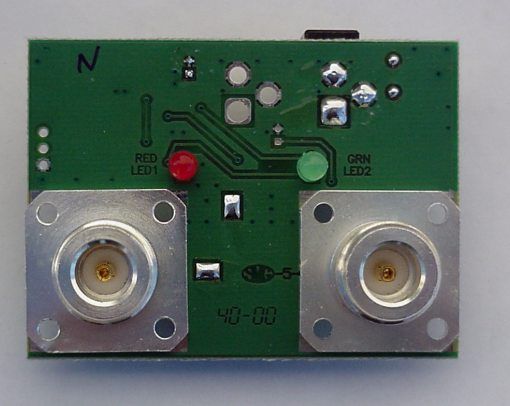
Document Text
Text extracted from the exhibit documents filed with the FCC. Open a document above to read the original.
Users Manual
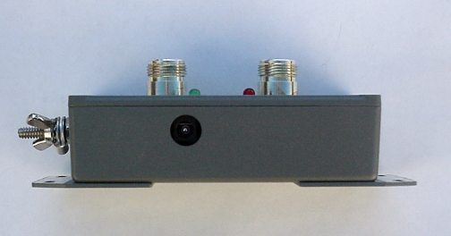
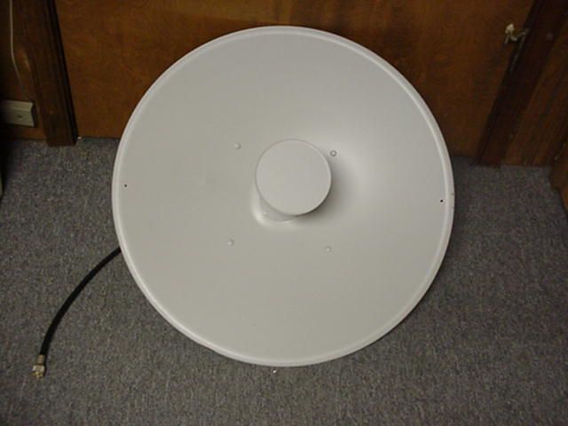
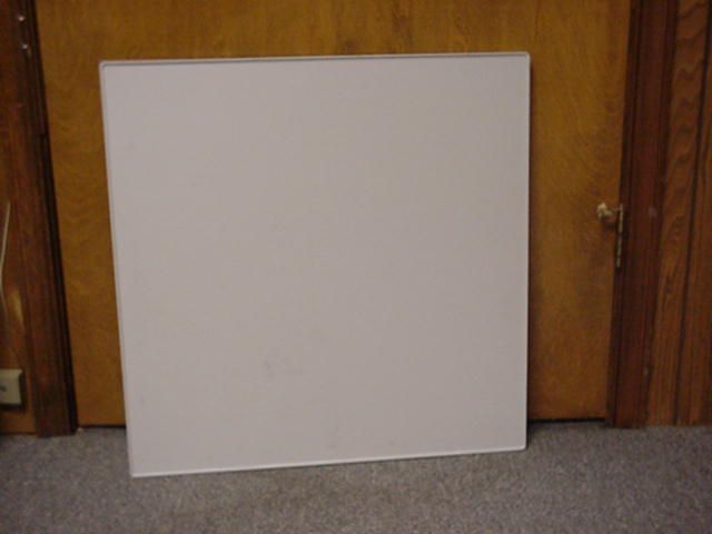
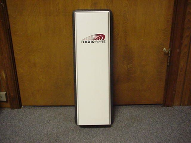
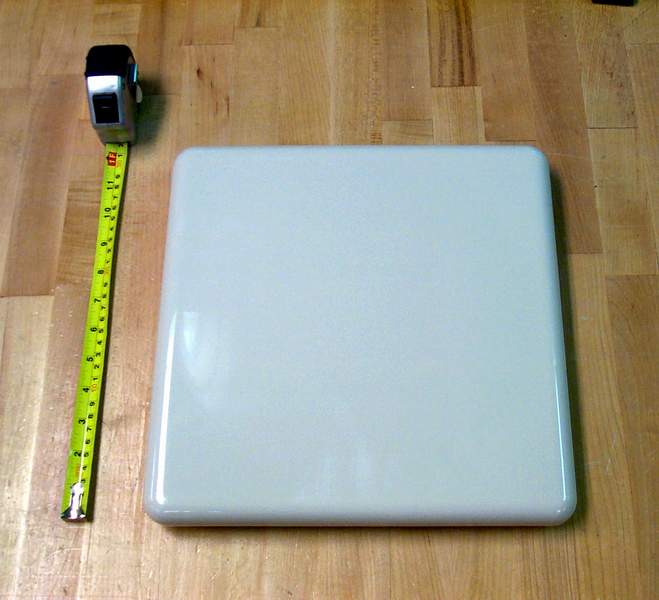
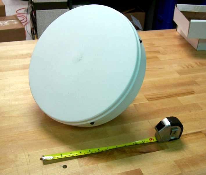
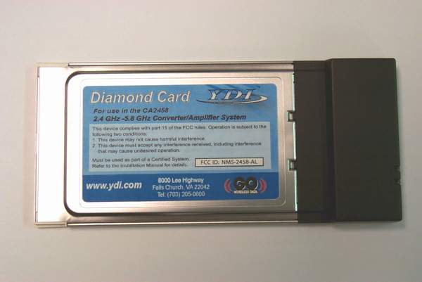
Notice in Installation Manual: FCC Radiation Exposure Statement This equipment complies with FCC radiation exposure limits set forth for an uncontrolled environment when installed as directed. This equipment should be installed and operated with fix-mounted antennas that are installed with a minimum of 2 meters of separation distance between the antenna and all persons’ body during normal operation. RF Exposure Calculations: The following information provides the minimum separation distance for the highest gain antenna provided with the Model: CA2458 Converter with Agere Extended WLAN Card, as calculated from FCC OET 65 Appendix B, Table 1B Guidelines for General Population/Uncontrolled Exposure. This calculation is based on the highest EIRP possible from the system, considering maximum power and antenna gain, and considering a 1.0 mW/cm^2 uncontrolled exposure limit. The Friss formula used was: S = (Po*G) / (4*Pi*r^2) or r = (Po*G) / (4*Pi*S) Where S = 1.0 mW/cm^2 for 5800 MHz Where Po = 250 mW (Peak RF) Where G = Isotropic antenna gain (numeric) Where r = Minimum Safe Distance from antenna (cm) For: 27 dBi Dish Antenna - ...... r = 100 cm The following table lists the antennas that will be provided with the system: Authorized Antennas ModelAntenna TypeAntenna Gain (dBi) Max EIRP (dBm) MPE Distance (CM) A5.8FP23One foot dish244871 A5.8FP27 Two foot dish 2751100 A5.8-1’ One foot flat panel 244871 A5.8-2’Two foot flat panel2751100 A5.8HP90-16Uni-directional antenna164028 Notes: 1. MPE distance figures are based on a conservative “worse case” prediction, i.e. +24 dBm into antenna and using formula S=EIRP/(4piR²) and no calculation for duty factor. In practice the minimum distance will be much shorter. (Ref. 2) 2. The minimum MPE distance has been calculated for the maximum allowed Power Density (S) limit of 1.0 mW/cm2 in the Frequency range 1500-100,000 MHz for uncontrolled environments (Ref. 2). Reference: 1. FCC Part 15, sub-clause 15.247 (b) (4) 2. FCC OET Bulletin 65, Edition 97-01 3. FCC Supplement C to OET Bulletin 65, edition 97-01
Users Manual
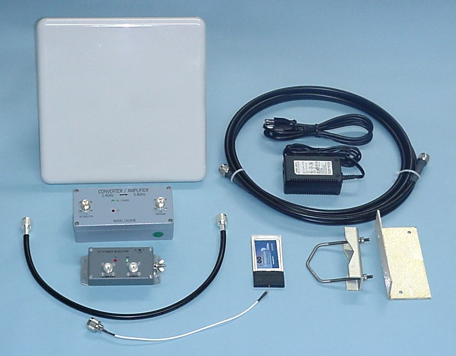
i TABLE OF CONTENTS 1.0 DESCRIPTION ..................................................................................................................................................1 2.0 CONVERTER (ODU) FEATURES..................................................................................................................2 3.0 OUTDOOR UNIT SPECIFICATIONS............................................................................................................4 4.0 CONVERTER KIT ............................................................................................................................................5 5.0 INSTALLATION INSTRUCTIONS -- INTRODUCTION............................................................................5 6.0 RADIO FREQUENCY SAFETY......................................................................................................................6 7.0 SITE SELECTION AND SYSTEM ENGINEERING ....................................................................................6 8.0 OUTDOOR CONVERTER MOUNTING .......................................................................................................7 9.0 DC INJECTOR INSTALLATION .................................................................................................................. 7 10.0 TYPICAL ODU INSTALLATION..................................................................................................................8 11.0 LINK TEST PERFORMANCE .......................................................................................................................8 12.0 INSTALLATION DETAILS – TYPICAL INSTALLATION.......................................................................8 13.0 CONVERTER INDICATORS AND CONNECTORS ................................................................................10 14.0 DC POWER INJECTOR................................................................................................................................10 15.0 DC POWER INJECTOR INDICATORS AND CONNECTORS ..............................................................11 16.0 POWER SUPPLY ...........................................................................................................................................11 17.0 OPERATION ...................................................................................................................................................12 APPENDIX A ............................................................................................................................................................13 APPENDIX B.............................................................................................................................................................14 APPENDIX C ............................................................................................................................................................16 © 2002 Young Design, Inc. All Rights Reserved. No part or parts of this document may be reproduced, translated, stored in any electronic retrieval system or transmitted in any form or by any means electronic, mechanical, photocopied, recorded or otherwise without prior written permission of Young Design, Inc. ii Professional Installation Required The Model CA2458 Converter/Amplifier, WLAN radio card, antenna, cables and accessories must be installed as a system by experienced antenna installation professionals who are familiar with Radio Frequency (RF) issues such as gains and losses, as well as local building and safety codes. Failure to do so will void the product warranty and may expose the end user to excessive RF hazard. Regulations regarding maximum antenna gains, power output and maximum permissible exposure vary from country to country. It is the responsibility of the end user to operate within the limits of these regulations and to ensure that the professional installers who install this device are aware of these regulations. All antennas are intended to be installed outdoors. SAFETY WARNING This equipment complies with FCC radiation exposure limits set forth for an uncontrolled environment when installed as directed. This equipment should be installed and operated with fix-mounted antennas that are installed such that the main lobe(s) of these antennas are located at a minimum of 2 meters between the antenna and all persons during normal operation FCC NOTICE To comply with FCC part 15 rules, the CA2458 Converter/Amplifier must only be used as a system as FCC certified. The system must also be professionally installed to ensure compliance with the Part 15 certification. It is the responsibility of the operator and professional installer to ensure that only certified systems are deployed in the United States (or where FCC rules apply). Further, pursuant to FCC Part 15 regulations, Section 15.247(b)(3)(iii), the installer must ensure that the high-gain directional antenna used in this system is used exclusively for fixed, point-to-point operations and that multiple co-located intentional radiators transmitting the same information are not used. Please visit our web site (www.ydi.com ) to see other YDI systems certified by the FCC. This device complies with Part 15 of the FCC rules. Operation is subject to the following two conditions: 1) This device may not cause harmful interference. 2) This device must accept any interference received, including interference that may cause undesired operation. iii LIMITED WARRANTY Young Design, Inc. (YDI) warrants that your device is free of defects in material and workmanship for a period of one year after initial purchase. YDI will, in this period, repair or replace any YDI product returned to the factory, freight prepaid. The YDI warranty covers repairs or replacement (at YDI’s option) of the product only. YDI is not responsible for the cost of removal, reinstallation or shipping to the place of repair. YDI does not extend or modify its warranty period…
Text truncated - open the document above for the full version.
Cover Letter(s)
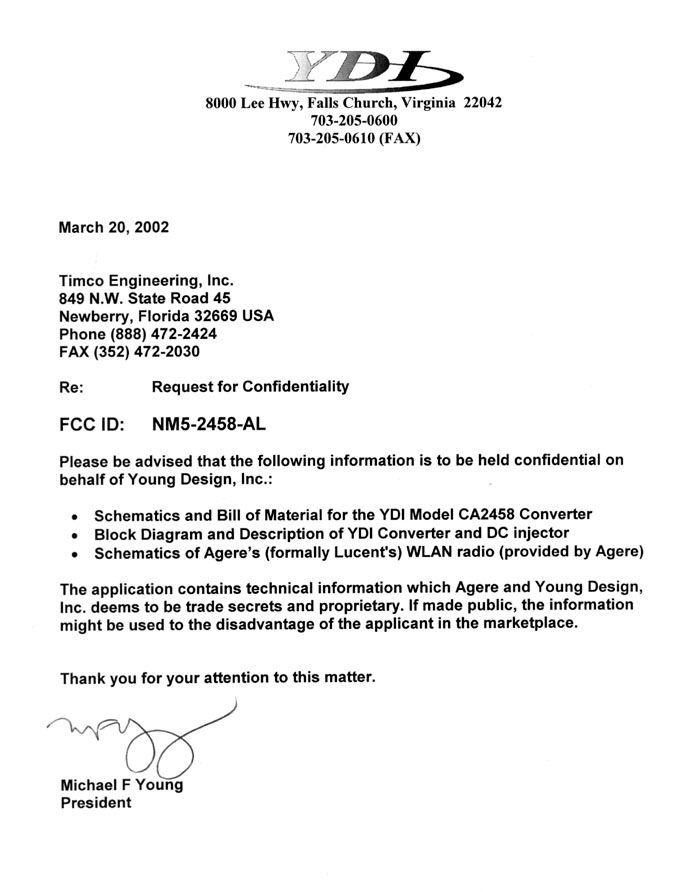
C:\windows\TEMP\probonholdemail.doc TIMCO TIMCOTIMCO TIMCO ENGINEERING INC. 849 NW State Road 45 Newberry, Florida 32669 http://www.timcoengr.com 888.472.2424 F 352.472.2030 email: tei@t imcoengr.com 12 April 2002 FCC SUBJECT: YOUNG DESIGN, INC. FCC ID: NM5-2458-AL MODEL: To Whom It May Concern: Included in the documents you will find justification for why the processing gain was measured in the way that it was which seems reasonable & justified to me. Sincerely, Sid Sanders
Cover Letter(s)
Mike Foster Director of Engineering Young Design, Inc. 8000 Lee Highway Falls Church, VA 22042 (703) 205-0073 [email protected] Timco Engineering Inc. 849 NW State Road 45 Newberry, Florida 32669 Reference: Job # 270UC2 FCC ID: NM5-2458-AL Mr. Sid Sanders, In response to your question, “Please explain how the RF power output is limited.” Please refer to the NM5-2458-AL System block diagram as shown in Figure 1, and as submitted to Timco Engineering’s web site. Figure 1 - System Block Diagram The WLAN 802.11b card has a transmit level regulated on-board to +15dBm (ref: Agere datasheet), as measured at the output connector of the device. The RF jumper cable and DC Injector have a combined insertion loss of approximately 1.5 dB. The coaxial cable loss from the Injector to the outdoor converter/amplifier module is specified to be a minimum of 5 dB. The outdoor module is a linear frequency block converter with fixed transmit conversion gain amplification set to 14 dB. The system installation manual stipulates that the system requires professional installation, and that a minimum cable length (and specific amount of loss) is required between the DC Injector and the outdoor module. Tables of commonly used cables and their minimum required lengths are provided to aid the installer. Given the specifications of nominal 15 dBm P-out from the WLAN device, the 1.5 dB loss from the jumper and DC Injector, and a specified minimum insertion loss of 5 dB for the coaxial cable, the nominal input level to the CA2458 outdoor module is at or below 10 dBm which is well within linear operation of the module. In summary, the RF power is limited because the RF transmit power is limited by the WLAN device, and because the system employs fixed / minimum losses between that device and the fixed-gain outdoor module. In response to your request for an explanation of why Processing Gain tests were conducted at 2.4 GHz. In the past, the Commission has noted that amplification of IEEE 802.11b signals do not impact the system Processing Gain. YDI’s application is for a direct sequence spread spectrum system operating on the 5725 to 5850 MHz band, as authorized by Section 15.247, that complies with all technical requirements in that section. This system is comprised of 2.4 GHz and 5.8 GHz elements, as shown above in Figure 1. The block diagram depicting the internal functions of the 5.8 GHz module, a CA2458 converter/amplifier, is shown below in Figure 2. Figure 2 - Converter Module Block Diagram The 5.8 GHz section of the system, within the CA2458, does not transmit, or receive, but rather translates and amplifies. There is no modulation or demodulation occurring in the CA2458 and this component provides frequency translation and signal amplification without any additional modulation, or demodulation, coding, or decoding. As the processing gain is achieved by the modulation and coding methods in the baseband transmitter, and is realized in the baseband receiver section, the processing gain at 2.4 GHz sets the system Processing Gain. Since the Commission acknowledges that amplification of IEEE 802.11b DSSS signals do not impact the system Processing Gain, we are asserting that a linear frequency translation also does not impact the system Processing Gain. As an example, Complementary Code Keying (CCK) modulation used in IEEE 802.11b achieves processing gain via bandwidth reduction (9dB) and coding gain (2dB). A linear amplification, and linear block frequency conversion of such signals neither modifies the occupied bandwidth of the signal or in any way modifies the coding methods employed. Indeed, no companding, compression, or notable distortion or non-linearities are introduced in to the signal transmission channel. In addition, no modifications to the 802.11b device receive threshold or receive sensitivity are made. If a module or device were to modify or distort the modulation envelope of the desired signal, or degrad the SNR or the J/S signal ratio, degradation of the Processing Gain would occur. For this reason, since that the CA2458 is a bi-directional, linear block frequency converter with fixed linear gain amplification, used as a module in this system, the processing gain of the receiver, operating at 2.4 GHz sets the system Processing Gain. In order to demonstrate that the CA2458 section of this system operates as a linear block converter and amplifier, and provides net system gain without modification of the modulation, sample laboratory measurements are hereby summarized: Input Frequency (MHz) Output Frequency +/- 10kHz 2400.005728.00 2405.005733.00 2410.005738.00 2415.005743.00 2420.005748.00 2425.005753.00 2430.005758.00 2435.005763.00 2440.005768.00 2445.005773.00 2450.005778.00 2455.005783.00 2460.005788.00 2465.005793.00 2470.005798.00 2475.005803.00 2480.005808.00 2485.005813.00 2490.005818.00 A sample of data collected on the CA2458 module demonstrating linear frequency translation is shown in Figure 3. Conversion is a clean, linear translation of 3.32800 GHz in both directions. Phase noise of the LO used in the module for the conversion is better than: -75dBc/Hz @ 10kHz -95dBc/Hz @ 100kHz Figure 3 - Table of Measured Freque ncy Conversion Linearity Treating the CA2458 as a simple active mixer, and using an HP8753E Network Analyzer configured to measure conversion loss linearity, a plot was taken (with 1dB used as the vertical scale resolution) to demonstrate the flatness across the band. Reverse gain is similarly measured for linearity. Figure 4 - 'Conversion Loss' Measured Linearity Figure 5 depicts the CA2458 as configured for the conversion measurements on the Network Analyzer. Figure 5 - 'Conversion Loss' Linearity Verification The CA2458 was measured for amplifier and power gain linearity. A representation of this linearity is depicted in Figure 6, and the test equipment configuration is shown in Figure 7. Power Gain Linearity 0 5 10 15 20 25 30 02468101214 Pin Pout Figure 6 - Power Gain Measured Linear…
Text truncated - open the document above for the full version.
Cover Letter(s)
C:\windows\TEMP\probonholdemail.doc TIMCO TIMCOTIMCO TIMCO ENGINEERING INC. 849 NW State Road 45 Newberry, Florida 32669 http://www.timcoengr.com 888.472.2424 F 352.472.2030 email: tei@t imcoengr.com 22 July 2002 Mr. Joe dichoso FCC SUBJECT: YOUNG DESIGN, INC. FCC ID: NM5-2458-AL REFERENCE: TC 325879 Mr. Dichoso, 1.This is not a stand alone converter, as you can see in the user manual it is a complete system. We have attached a correct user manual. 2.With regards to the processing gain, since the conversion gain is unity and the bandwidth of the EUT is greater than the bandwidth of the modulation it seemed with in “good engineering practice” to measure the procession gain at the converted frequency. 3 and 4. The RF Card is a previously approved device and is only part of this system. 5.Photos of the 2 additional antennas have been submitted. 6 and 7.The Grant has been corrected as requested. This is not a converter but a system. Sincerely, Sid Sanders
Operational Description
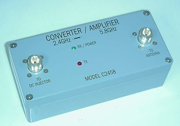
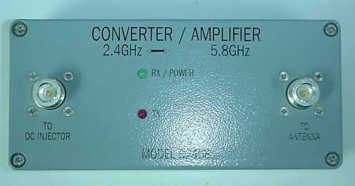
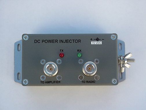
CONFIDENTIAL POLE MOUNTED BI-DIRECTIONAL RF CONVERTER/AMPLIFIER Background The 2.4 GHz license-free radio band is widely used for Spread Spectrum Wireless Local Area Network (WLAN) applications. The most commonly used technology in the 2.4 GHz band are devices designed to comply with the IEEE 801.11 and 802.11b standards. These standards specify half-duplex operation in a Time Division Duplex (TDD) mode. In TDD, each radio can receive and transmit, but not at the same time. Two-way duplex communication takes place by sharing the airwaves based on time slots. One unit transmits and the other listens. Once the first unit goes off the air and switches to receive mode, the other unit is free to use the airwaves and send its data. If for some reason, two devices in communication with each other transmit at the same time, the data packets will be lost and will need to be retransmitted. Most of these WLAN devices use the 802.11b standard. This standard defines fourteen Direct Sequence Spread Spectrum (DSSS) channels separated by five MHz, (i.e., 2412 MHz, 2517 MHz, 2422 MHz, etc.) only the first eleven of which can be used in the United States. Each channel occupies about 22 MHz of bandwidth. Therefore, at any one location (e.g., office, rooftop, or radio tower) a maximum of three 801.11b DSSS radio channels can be used – typically channels 1, 6 and 11. If channels too close to each other are used (e.g., channels 5 and 7), the sideband noise from the radiated spectrum from one transmitter will interfere with the reception of the remote client signals on other co-located radios. Thus, in most installations, no more then three 802.11b radio channels are used at any one location. There are many manufacturers that make WLAN devices for this band and many millions of these devices have been sold worldwide. This has reduced the cost of these high-performance radio devices serving to expand their proliferation. These WLAN devices were originally designed for indoor use to provide wireless connectivity to PCs and other devices. However, using external outdoor installations with these devices has enabled long-range outdoor applications. These devices have proliferated in recent years crowding the 2.4 GHz license-free radio band. Also operating on this band are microwave ovens, cordless telephones, low-power video surveillance CONFIDENTIAL Spread Spectrum radio devices to operate in the 5.8 GHz band thereby avoiding all the interference found on the 2.4 GHz band. Brief Description of Drawings Figure 1 shows a typical installation drawing with Converter Amplifier mounted near the antenna with coax cables connecting it to the DC Injector and radio transceiver Figure 2 shows a simple block diagram illustrating how the Converter Amplifier module translates radio frequencies Figure 3 shows the circuit elements found inside the bi-directional Converter Amplifier module Figure 4 shows an alternate form of the Converter Amplifier where no DC Injector is required when the radio transceiver and antenna are all co-located. Functional Description Refer to Figure 1. In transmit mode, radio frequency (RF) signals generated in the radio device connected to Converter Amplifier 1 on 2.4 GHz band are converted to 5.8 GHz band. Likewise, when Converter Amplifier 1 is in the receive mode, received signals entering Converter Amplifier 1 in 5.8 GHz band are converted to 2.4 GHz band. Converter Amplifier 1 is a half-duplex device and automatically switches from receive to transmit mode. The device can be built to either up or down convert. In other words, the converted frequencies could be either higher or lower in frequency than the operating frequency of the radio it is connected to. CONFIDENTIAL Figure 2 details the typical installation. Normally, antenna connector 21 is connected via coax cable 3 and external antenna 87 tuned to operate on to the 5.8 GHz band. In the receive mode, RF signals picked up by antenna 87 enter Converter Amplifier 1 at antenna connector 21. They are then converted to 5.8 GHz band, amplified and fed out of Converter Amplifier 1 at radio connector 20 to DC (direct current) Power Injector 2. The converted RF signal travels down coax cable 4 to DC Power Injector 2 through RF connector 72. The signal then passes through DC Power Injector 2, out RF connector 60 and to Transceiver Radio 6 thru the second coax cable 9 attached to Transceiver Radio 6. When Transceiver Radio 6 goes into the transmit mode, RF energy from radio 6 travels the same path. The signal passes from radio 6 through coax cable 9 in RF connector 60 to DC Power Injector 2 on through coax cable 4 to Converter Amplifier 1 through radio connector 20. The signal is then converted to 5.8 GHz band, amplified and fed out of Converter Amplifier 1 at antenna connector 21 to external antenna 87 via coax cable 3. DC Power Injector 2 serves the primary purpose of injecting DC power onto coax cable 4 to power the electronics in Converter Amplifier 1. Additionally, DC Power Injector 2 offers lightning and power surge protection as well as LEDs to show the operational status of the system. CONFIDENTIAL Figure 3 shows the circuit components inside Converter Amplifier 1. In the receive mode, the received RF signal enters Converter Amplifier 1 at antenna connector 21. The signal is filtered by 5.8 GHz band by Bandpass Filter 36 via electronic switch 35 and proceeds into noise amplifier (LNA) 30. This signal is fed into receive RF Mixer 29 where it is mixed with the signal from Local Oscillator (LO) 31. The resulting signal is converted or translated to RF 2.4 GHz band and fed though 2.4 GHz band Bandpass Filter 27. The signal is then passed through input switch 24 and to radio connector 20 where it is ultimately presented to Transceiver Radio 6 from the transmission coax cable 4, through DC Power Injector 2 and along coax cable 9. When Transceiver Radio 6 is operated in the transmit mode, the RF energy enters Converter Amplifier 1 at the radio connector…
Text truncated - open the document above for the full version.
Test Report
Y Y O O U U N N G G D D E E S S I I G G N N , , I I N N C C . . F F C C C C I I N N F F O O R R M M A A T T I I O O N N FCC ID: NM5-2458-AL Page 2 of 45 R R R F F F M M M e e e a a a s s s u u u r r r e e e m m m e e e n n n t t t R R R e e e p p p o o o r r r t t t P P P r r r e e e p p p a a a r r r e e e d d d b b b y y y : : : N N N a a a t t t i i i o o o n n n a a a l l l C C C e e e r r r t t t i i i f f f i i i c c c a a a t t t i i i o o o n n n L L L a a a b b b o o o r r r a a a t t t o o o r r r y y y 8370 Court Avenue, Suite B-1 Ellicott City, Maryland 21043 (410) 461-5548 I I I n n n S S S u u u p p p p p p o o o r r r t t t o o o f f f : : : F F F o o o r r r : : : Young Design, Inc. 8000 Lee Highway Falls Church, VA 22042 Model: CA2458 Converter with Agere Extended WLAN Card FCCID: NM5-2458-AL Demonstration of Compliance with FCC Rules Part 15.247 No part of this report may be reproduced without written approval of National Certification Laboratory December 23, 2001 FCC APPLICATION FOR CERTIFICATION FCC ID: NM5-2458-AL Page 3 of 45 TABLE OF CONTENTS 1.0 General Information .................................................................................................................................... 5 1.1 Summary ............................................................................................................................................. 5 1.2 Test Methodology ................................................................................................................................... 5 1.3 Test Facility............................................................................................................................................. 5 2.0 Description of Equipment Under Test (EUT)........................................................................................ 6 2.1 EMI Countermeasure .............................................................................................................................. 6 3.0 Test Program ............................................................................................................................................. 7 4.0 Test Configuration For Antenna Terminal Conducted......................................................................... 8 4.1 Peak Power Test Results ......................................................................................................................... 9 4.2 6 dB Emission Bandwidth Test Results ................................................................................................ 10 4.2.1 6 dB Bandwidth Emissions (100 kHz Res. BW) Low Channel Plot ............................................ 11 4.2.2 6 dB Bandwidth Emissions (100 kHz Res. BW) Mid Channel Plot ............................................. 12 4.2.3 6 dB Bandwidth Emissions (100 kHz Res. BW) High Channel Plot............................................ 13 4.3 RF Antenna Conducted Spurious/Harmonics Emissions...................................................................... 14 4.3.1 FCC Part 15.247(c) Conducted Spurious, 2412 MHz Frequency Of Carrier ............................... 15 4.3.2 FCC Part 15.247(c) Conducted Spurious, 2437 MHz Frequency of Carrier ................................ 16 4.3.3 FCC Part 15.247(c) Conducted Spurious,2462 MHz Frequency of Carrier ................................. 17 4.4 Conducted Bandedge Emissions Test Results ...................................................................................... 18 4.4.1 Low Channel Conducted Bandedge Emissions Plot ..................................................................... 18 4.4.2 High Channel Conducted Bandedge Emissions Plot .................................................................... 19 4.5 Power Spectral Density ......................................................................................................................... 20 4.5.1 Power Spectral Density Low Channel Plot ................................................................................... 21 4.5.2 Power Spectral Density Mid Channel Plot.................................................................................... 22 4.5.3 Power Spectral Density High Channel Plot .................................................................................. 23 5.0 Test Configuration For Conducted And Radiated Emissions............................................................ 24 6.0 A.C. Conducted Emissions Scheme....................................................................................................... 25 6.1 AC Conducted Emissions Data Table ................................................................................................... 26 FCC ID: NM5-2458-AL Page 4 of 45 7.0 Radiated Emissions Scheme................................................................................................................... 27 7.1 16 dBi Uni-directional Antenna @ 5740 MHz - Radiated Emissions Data Table .............................. 28 7.2 16 dBi Uni-directional Antenna @ 5770 MHz - Radiated Emissions Data Table ............................... 29 7.3 16 dBi Uni-directional Antenna @ 5811 MHz - Radiated Emissions Data Table ............................... 30 7.4 27 dBi Dish Antenna @ 5740 MHz - Radiated Emissions Data Table ............................................... 31 7.5 27 dBi Dish Antenna @ 5770 MHz - Radiated Emissions Data Table ............................................... 32 7.6 27 dBi Dish Antenna @ 5811 MHz - Radiated Emissions Data Table ............................................... 33 7.7 27 dBi Flat Panel Antenna @ 5740 MHz - Radiated Emissions Data Table ....................................... 34 7.8 27 dBi Flat Panel Antenna @ 5770 MHz - Radiated Emissions Data Table ....................................... 35 7.9 27 dBi Flat Panel Antenna @ 5811 MHz - Radiated Emissions Data Table ....................................... 36 8.0 RF Exposure Statement.........................…
Text truncated - open the document above for the full version.
Test Setup Photos
E E E X X X H H H I I I B B B I I I T T T 1 1 1 . . . 2 2 2 R R R A A A D D D I I I A A A T T T E E E D D D E E E M M M I I I S S S S S S I I I O O O N N N S S S P P P H H H O O O T T T O O O G G G R R R A A A P P P H H H S S S
Contact Information
Applicant
John Hutchings(Product Integrity Manager)
Test Firm
National Certification LaboratoryBrian Haghtalab
Technical Specifications
| # | Rule Parts | Frequency Range | Power Output |
|---|---|---|---|
| 1 | 15C | 5.74 GHz - 5.81 GHz | 250.00 mW |
Other Applications from YDI Wireless

NM5-MB-49-HP
Apr 12, 2005Point to Point Wireless Bridge
Equipment Class
TNB - Licensed Non-Broadcast Station Transmitter
NM5-MB-49
Jul 27, 2004Wireless Network Bridge
Equipment Class
TNB - Licensed Non-Broadcast Station Transmitter
NM5-MB-HP
Jul 07, 2004Outdoor Transmitter
Equipment Class
DTS - Digital Transmission System
NM5-MB-ST
Jun 29, 2004Point-to-Point Transmitter
Equipment Class
NII - Unlicensed National Information Infrastructure TX
NM5-CX-DS3-ETH-24
Mar 14, 2004Point to Point 24GHz Microwave Radio
Equipment Class
DXX - Part 15 Low Power Communication Device Transmitter