NM5-A2400SSpread Spectrum Transmission System
YDI Wireless
Click to zoom
Application Details
- Equipment Class
- DSS - Part 15 Spread Spectrum Transmitter
- Date of Grant
- Jul 15, 2001
- Application Purpose
- Original Equipment
- Date of Application
- Jul 15, 2001
- Equipment Note
- Spread Spectrum Transmission System
- Frequency Range
- 2412.00000000 - 2462.00000000
- Company
- YDI Wireless
- Country
- United States
Documents & Files
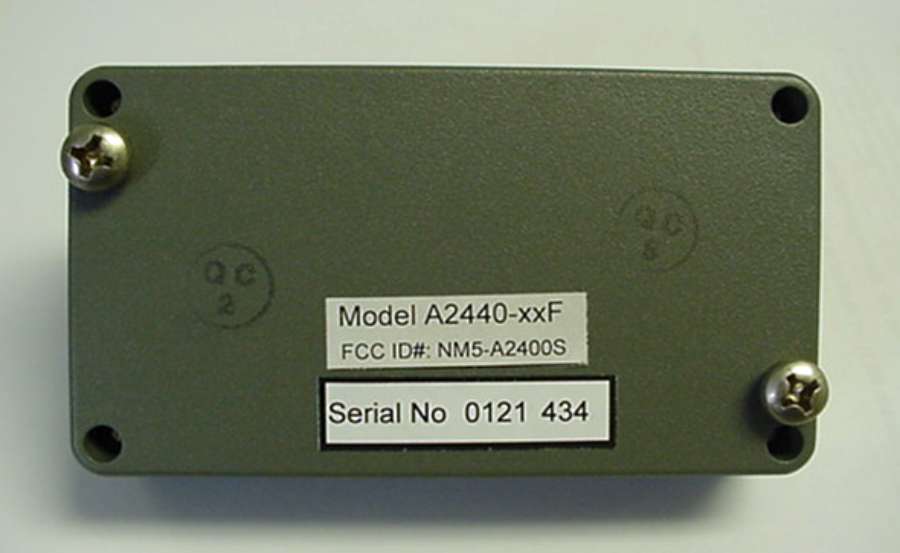
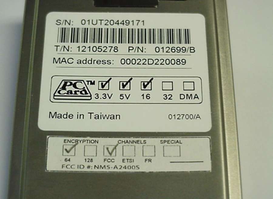
Document Text
Text extracted from the exhibit documents filed with the FCC. Open a document above to read the original.
Users Manual
Version 2.4 July, 2001 LIMITED WARRANTY Young Design, Inc. (YDI) warrants that your device is free of defects in material and workmanship for a period of one year after initial purchase. YDI will, in this period of time, repair or replace, any YDI product returned to the factory, freight prepaid. The YDI warranty covers repairs or replacement (at YDI’s option) of the product only. YDI is not responsible for the cost of removal, reinstallation, or shipping to the place of repair. YDI does not extend or modify its warranty period as a result of repair or replacement. YDI reserves the right to void a warranty and/or make reasonable charges for repair of a unit if the warranty seal is broken or the unit displays evidence of misuse, abuse, or tampering. YDI is not responsible for damage to any other equipment or property, or any other consequential or incidental damages of any kind, whether based on contract, negligence, or strict liability. Maximum liability shall not in any case exceed the purchase price of the unit. Warranties give you (the buyer) specific legal rights. You may also have other rights that vary from state to state. This warranty is only extended to purchases made in the United States of America or its possessions. Warranty Notice The AMP2440 warranty is null and void if any of the following occurs: 1. The amplifier is opened. 2. The antenna connections are not properly waterproofed. 3. The amplifier is operated with no antenna attached. 4. Improper connectors are used. 5. The amplifier is mounted outdoors with the connectors facing any direction except downwards. ©© 2000, 2001 Young Design, Inc All Rights Reserved. No part or parts of this document may be reproduced, translated, stored in any electronic retrieval system, or transmitted, in any form or by any means, electronic, mechanical, photocopying, recording, or otherwise, without the prior written permission Young Design, Inc. Important FCC Notice This device complies with part 15 of the FCC rules. Operation is subject to the following two conditions: (1) This device may not cause harmful interference, and (2) This device must accept any interference received, including interference that may cause undesired operation. TABLE OF CONTENTS 1. DESCRIPTION.........................................................................................................................................................................1 2. AMPLIFIER FEATURES...............................................................................................................................................1 2.1 GENERAL SPECIFICATIONS............................................................................................................................2 3. AMPLIFIER KIT.....................................................................................................................................................................3 4. INSTALLATION AND CABLING INSTRUCTIONS.........................................................................3 5. AMPLIFIER CONNECTIONS AND INDICATORS.............................................................................5 6. DC POWER INJECTOR OPERATION..........................................................................................................5 7. DC POWER INJECTOR CONNECTIONS AND INDICATORS.........................................6 8. POWER SUPPLY..................................................................................................................................................................6 9. OPERATION...............................................................................................................................................................................7 TABLE A - CONVERSIONS FROM DBM TO WATTS........................................................................9 TABLE B - TYPICAL CABLE ATTENUATION VALUES.................................................................9 APPENDIX A: CALCULATING POWER.........................................................................................................10 APPENDIX B: FCC PART 15 CERTIFIED SYSTEMS.....................................................................11 Professional Installation Required The amplifier and antennas used must be professionally installed by experienced antenna installation professionals who are familiar with RF issues (such as gains and losses) as well as local building and safety codes. Failure to do so will void the product warranty and may expose the end user to excessive Radio Frequency hazard. Regulations regarding maximum antenna gains, amplifier power gain, and maximum permissible exposure vary from country to country. It is the responsibility of the end user to operate within the limits of these regulations and to ensure that the professional installers who install this device are aware of these regulations. All antennas are intended to be installed outdoors. 1 1. Description The AMP2440 is a bi-directional amplifier designed for extending the range of 2.4 GHz wireless radio modems, Wireless LAN cards, Access Points and wireless bridges. The units provide transmit power amplification as well as receive signal gain. The amplifier is installed right at the antenna’s feed point, providing maximum effectiveness of transmit power. This has the effect of compensating for signal loss in the transmitter cable to the antenna. Likewise, the Low Noise Amplifier (LNA) in the AMP2440 boosts the receive signal right at the antenna prior to experiencing the loss in the transmission cable to the radio. This gain completely overcomes the losses in the transmission cable between the amplifier and the radio. This results in the lowest possible system Noise Figure. In fact, use of the amp will actually increase the receiver sensitivity by a few dB! The ultimate result is the best receiver sensitivity and maximum possible range for whatever antenna is used. The amplifier box is weatherpr…
Text truncated - open the document above for the full version.
Cover Letter(s)
Mr. William Graff President American Telecommunications Certification Body Inc. 6731 Whittier Avenue McLean, VA 22101 RE: Young Design, Inc. FCC ID: NM%-A2400S Dear Mr. Graff: This is in reference to the June 27, 2001 request for technical information for the above subject project. 1- The units on page 11 have been corrected from dBm to MHz. Please refer to the submitted FCC Report. 2- The EUT can be step through various data rates and emission envelop does not change. 3- Please refer to submitted User’s Manual. 4- Please refer to FCC Report sections 7.37 and 7.38. 5- Please refer to submitted User’s Manual. Please note that the FCC Notice is on the inside front cover of the manual in clear, bold notation. Should you have any concerns or questions, please contact me. Best regards, Brian Haghtalab Operations Manager
Cover Letter(s)
American Telecommunications Certification Body Inc. 6731 Whittier Ave, McLean, VA 22101 June 27, 2001 RE: Young Design FCC ID: NM5-A2400S A couple comments on this Application 1.) FYI: The units on pp. 11 Section 4.2 of the test report appear to be wrong. Shouldn’t they be MHz and not dBm? 2.) Can the EUT be stepped through various data rates? If so, did the emission envelope change? 3.) Appendix B of the owners manual indicates use of this transmission system with a Nokia product, not a Lucent / Agree. Is this correct? 4.) I am not certain I can show compliance with the radiated band edge requirements below 2390MHz and above 2483.5MHz. Please provide radiated band edge data using a SA setting of 1MHz RBW in both peak and average modes for the highest gain antenna. Add this as an appendix to the existing test report. 5.) This equipment (the amplifier) appears larger than the palm of the hand. Therefore the language of 15.19(a)(3) should appear on the device. If not the device than somewhere in the manual. If it exists in the manual please indicate where. If you have any questions about this Application, please contact me directly. William H. Graff Examining Engineer President and Director of Engineering mailto:[email protected] The items indicated above must be submitted before processing can continue on the above referenced application. Failure to provide the requested information may result in application termination. Correspondence should be considered part of the permanent submission and may be viewed from the Internet after a Grant of Equipment Authorization is issued. Please do not respond to this correspondence using the email reply button. In order for your response to be processed expeditiously, you must submit your documents through the AmericanTCB.com website. Also, please note that partial responses increase processing time and should not be submitted. Any questions about the content of this correspondence should be directed to the sender.
External Photos
EXTERNAL PHOTO 2.4 GHz Bi-Directional Amplifier Front View EXTERNAL PHOTO DC Power Injector Front View
Internal Photos
INTERNAL PHOTO 2.4 GHz Bi-Directional Amplifier Front View INTERNAL PHOTO 2.4 GHz Bi-Directional Amplifier Rear View INTERNAL PHOTO DC Power Injector Front View INTERNAL PHOTO DC Power Injector Rear View
RF Exposure Info
8.0 RF Exposure Statement: Notice in Installation Manual: FCC Radiation Exposure Statement This equipment complies with FCC radiation exposure limits set forth for an uncontrolled environment when installed as directed. This equipment should be installed and operated with fix-mounted antennas that are installed with a minimum of 2 meters of separation distance between the antenna and all persons’ body during normal operation. RF Exposure Calculations: The following information provides the minimum separation distance for the highest gain antenna provided with the Lucent Agere WaveLAN Card with Model AMP2440-RxF Amplifier, as calculated from FCC OET 65 Appendix B, Table 1B Guidelines for General Population/Uncontrolled Exposure. This calculation is based on the highest EIRP possible from the system, considering maximum power and antenna gain, and considering a 1.0 mW/cm^2 uncontrolled exposure limit. The Friss formula used was: S = (Po*G) / (4*Pi*r^2) or r = (Po*G) / (4*Pi*S) Where S = 1.0 mW/cm^2 for 2400 MHz Where Po = 250 mW (Peak RF) Where G = Isotropic antenna gain (numeric) Where r = Minimum Safe Distance from antenna (cm) For: 24 dBi Grid Dish Antenna - Lucent or YDI models ...... r = 71 cm
Test Report
Y Y O O U U N N G G D D E E S S I I G G N N , , I I N N C C . . F F C C C C I I N N F F O O R R M M A A T T I I O O N N FCC ID: NM5-A2400SPage 2 of 77 R R R F F F M M M e e e a a a s s s u u u r r r e e e m m m e e e n n n t t t R R R e e e p p p o o o r r r t t t P P P r r r e e e p p p a a a r r r e e e d d d b b b y y y : : : N N N a a a t t t i i i o o o n n n a a a l l l C C C e e e r r r t t t i i i f f f i i i c c c a a a t t t i i i o o o n n n L L L a a a b b b o o o r r r a a a t t t o o o r r r y y y 8370 Court Avenue, Suite B-1 Ellicott City, Maryland 21043 (410) 461-5548 I I I n n n S S S u u u p p p p p p o o o r r r t t t o o o f f f : : : F F F o o o r r r : : : Young Design, Inc. 8000 Lee Highway Arlington, VA 22042 Model: Lucent Agere WaveLAN Card with AMP2440 Amplifier FCCID: NM5-A2400S Demonstration of Compliance with FCC Rules Part 15.247 No part of this report may be reproduced without written approval of National Certification Laboratory June 4, 2001 FCC APPLICATION FOR CERTIFICATION FCC ID: NM5-A2400SPage 3 of 77 TABLE OF CONTENTS 1.0General Information.................................................................................................................................6 1.1Summary6 1.2Test Methodology...................................................................................................................................6 1.3Test Facility.............................................................................................................................................6 2.0Description of Equipment Under Test (EUT).........................................................................................7 2.1EMI Countermeasure..............................................................................................................................8 3.0Test Program8 4.0Test Configuration For Antenna Terminal Conducted.........................................................................9 4.1Peak Power Test Results.......................................................................................................................10 4.26 dB Emission Bandwidth Test Results................................................................................................11 4.2.16 dB Bandwidth Emissions (100 kHz Res. BW) Low Channel Plot............................................12 4.2.26 dB Bandwidth Emissions (100 kHz Res. BW) Mid Channel Plot.............................................13 4.2.36 dB Bandwidth Emissions (100 kHz Res. BW) High Channel Plot............................................14 4.3RF Antenna Conducted Spurious/Harmonics Emissions......................................................................15 4.3.1FCC Part 15.247(c) Conducted Spurious, 2412 MHz Frequency Of Carrier...............................16 4.3.2FCC Part 15.247(c) Conducted Spurious, 2437 MHz Frequency of Carrier................................17 4.3.3FCC Part 15.247(c) Conducted Spurious,2462 MHz Frequency of Carrier.................................18 4.4Conducted Bandedge Emissions Test Results......................................................................................19 4.4.1Low Channel Conducted Bandedge Emissions Plot.....................................................................19 4.4.2High Channel Conducted Bandedge Emissions Plot....................................................................20 4.5Power Spectral Density.........................................................................................................................21 4.5.1Power Spectral Density Low Channel Plot...................................................................................22 4.5.2Power Spectral Density Mid Channel Plot....................................................................................23 4.5.3Power Spectral Density High Channel Plot..................................................................................24 5.0Test Configuration For Conducted And Radiated Emissions............................................................25 6.0A.C. Conducted Emissions Scheme.......................................................................................................26 6.1AC Conducted Emissions Data Table...................................................................................................27 FCC ID: NM5-A2400SPage 4 of 77 7.0Radiated Emissions Scheme...................................................................................................................28 7.112 dBi Omni Antenna, 2412 MHz, 250mW Radiated Emissions Data Table......................................29 7.217dBi Long Panel Antenna, 2412 MHz, 250mW Radiated Emissions Data Table..............................30 7.318 dBi Flat Panel Antenna, 2412 MHz, 250mW Radiated Emissions Data Table...............................31 7.424 dBi Grid Dish Antenna, 2412 MHz, 250mW Radiated Emissions Data Table...............................32 7.512 dBi Wide Angle Antenna, 2412 MHz, 250mW Radiated Emissions Data Table............................33 7.612 dBi A24SP12A Flat Panel Antenna, 2412 MHz, 250mW Radiated Emissions Data Table............34 7.712 dBi Omni Antenna, 2437 MHz, 250mW Radiated Emissions Data Table......................................35 7.817 dBi Long Panel Antenna, 2437 MHz, 250mW Radiated Emissions Data Table.............................36 7.924 dBi Grid Dish Antenna, 2437 MHz, 250mW Radiated Emissions Data Table...............................37 7.1018 dBi Flat Panel Antenna, 2437 MHz, 250mW Radiated Emissions Data Table...............................38 7.1112 dBi Wide Angle Antenna, 2437 MHz, 250mW Radiated Emissions Data Table............................39 7.1212 dBi A24SP12A Flat Panel Antenna, 2437 MHz, 250mW Radiated Emissions Data Table............40 7.1312 dBi Omni Antenna, 2462 MHz, 250mW Radiated Emissions Data Table......................................41 7.1417 dBi Long Panel Antenna, 2462 MHz, 250mW Radiated Emissions Data …
Text truncated - open the document above for the full version.
Test Report
Nederland B.V. WCND FCC ID: WLPC24H/WLPCE24H Report No. 011734, Rev. B TEST REPORT Subject: Processing Gain For WaveLAN IEEE PC CARD type 2 HS Ref.: FCC Rules 47 CFR Part 15, Section 5.247d Report Prepared by: Maarten Visee May 6, 1999 Name Signature Date Concurrence: 1. Director of Engineering Bruce Tuch May 6, 1999 Name Signature Date 2. Team Captain Frans Hoekstra May 6, 1999 Name Signature Date Lucent WCND Confidential Information ©1999 FCC Processing Gain Measurements Results, FCCID WLPC24H/WLPCE24H, Report No. 011734, Rev. B. Lucent WCND Confidential ©1999 i Date Section Description 04/16/99, Rev. A Initial release. 05/6/99, Rev. B 2 Changed spreading gain into processing gain. 4.1 For data rates of 5.5 and 11 Mbit/s changed processing gain requirements of 9 dB into 10 dB. 4.2 Changed description for demodulated data availability at the interconnection between RF and DSP into the interconnection between DSP and digital circuits. Changed spreading gain into processing gain. 7.2, 7.3 Changed sub sections Measurement Results and Measurement Conclusion. Annex A Updated flow chart. Change History: FCC Processing Gain Measurements Results, FCCID WLPC24H/WLPCE24H, Report No. 011734, Rev. B. Lucent WCND Confidential ©1999 1 This document describes the Receiver Processing Gain verification measurements performed at the WaveLAN-II PC-Card Type 2, according to Ref.[2]. The Lucent WaveLAN-II PC-Card Type 2 product confirms to the minimum required 10 dB processing gain, as set forth by the FCC for operation in the 2.4 GHz ISM band. 1- Document FCC 97-114, Appendix C, Guidance on Measurements for Direct Sequence Spread Spectrum Systems. 2- Hardware Functional Specification for WaveLAN-II Embedded, High Speed, Doc. No. 011735, Rev. A, Source Organization Lucent Technologies WCND Utrecht. 3- Viterbi, A. J., Principles of Coherent Communications, New York, McGraw-Hill 1966. 4- Proakis, J.G., Digital Communications, New York, McGraw-Hill 1989, page 270. 4.1 Test introduction - FCC requirements: Part of FCC certification for the Lucent WaveLAN IEEE 802.11 High Speed compliant Network Interface Card (NIC) is a processing gain test. This test proves that the receiver of the tested product employs a true spread spectrum device receiver structure, taking full advantage of the direct sequence spread spectrum modulation technique. This test verifies the receiver processing gain to be 10 dB or more for a data rate of 1, 2, 5.5 and 11 Mbit/s, by monitoring the Bit Error Rate (BER) of the product under test for each data rate, while operating under strict defined received signal conditions. Several methods of showing compliance to the rules are possible, from a stepped CW jammer to a continuous sweeping CW interferer. For this test the discrete stepped CW jammer method was chosen, as described in Ref.[1]. Therefore a receiver input signal is applied to the product under test, in the presence of a Continuous Wave (CW) interference source, also referred to as CW jammer. The test takes place at the product Functional Specification (Ref.[2]) specified conditions for BER rate measurements, specifying a BER equal or better than 10^-8 at a 1. Summary: 2. Conclusion: 3. References: 4. Measurement description: FCC Processing Gain Measurements Results, FCCID WLPC24H/WLPCE24H, Report No. 011734, Rev. B. Lucent WCND Confidential ©1999 2 receiver input level of -55 dBm. For practical reasons these test are performed at -55 dBm or -53 dBm. This small deviation from the Functional Specification should not cause any deviation from the specified Bit Error Rate, since the received levels are well above the thermal noise. The test criteria for meeting the minimal processing gain is such that it takes the theoretical calculated SNR for the applied modulation technique and specified BER as a reference. From this given SNR the processing gain is subtracted, yielding the CW Jammer to Signal ratio J/S. From Ref. [4], likewise as Ref.[3] consulted in Ref. [1], it is determined that for a BER of 10^-8 the SNR (S/N)o equals: 13 dB @ 1 Mbit/s, 15 dB @ 2 Mbit/s, 15 dB @ 5.5 Mbit/s, 18 dB @ 11 Mbit/s. Thus the J/S ratio for a processing gain of 10 dB that must be met is calculated as: -13 + 10 = -3 dB @ 1 Mbit/s (DBPSK), -15 + 10 = -5 dB @ 2 Mbit/s (DQPSK), -15 + 10 = -5 dB @ 5.5 Mbit/s (CCK), -18 + 10 = -8 dB @ 11 Mbit/s (CCK). Two types of measurement corrections are allowed for as described in Ref.[1]. The first taking into account 2 dB implementation losses, thus increasing the absolute J/S ratio by 2 dB. The second correction allows for deleting the 20% worst- case frequencies in the processing gain test that causes the test at that CW interference to fail. This implies that for the considered 14 MHz wide measurement interval the worst case 57 CW jammer frequencies can be ignored, being those that result in received data errors/missing frames (20% of 14 MHz *(1 MHz/50 KHz)+1=(20%*281)+1=57). FCC Processing Gain Measurements Results, FCCID WLPC24H/WLPCE24H, Report No. 011734, Rev. B. Lucent WCND Confidential ©1999 3 4.2 Test sequence: The measurements are performed at a 50 KHz CW jammer raster. For each CW jammer frequency 10^8 bits are transmitted by the reference transmitter, and received by the product under test. For practical reasons 50.000 messages are transmitted. After blanking out frame overhead 1927 bits per frame are monitored. This results in 50.000 * 1927 = 9650000 transmitted bits for a BER test, which is a mere 1.4% less than the targeted 10^8 bits. Though it would be more elegant to show BER compliance for at least say ten times 10^8 transmitted/received bits, the time involved with this grows significantly. Since the CW interferer is stepped in a 50 KHz raster, covering the receiver bandwidth of 14 MHz, it is considered that the BER requirement is sufficiently met since such a multitude of measurements are taken. The total measurement is being performed under computer control, hereafter referred to as controller. It i…
Text truncated - open the document above for the full version.
Test Report
Measurement file output name is:5mbit.cnd Input command file name is:INPUT.CMDNote: 5.5 Mbit, 6 dB SIR tested for ( 15 dB SNR - 10.4 + 1 impl. losses). Input CW correction level:6dBTakes into account 1 dB of implementation loss (allowed 2 dB). Lowcount is:1000messages Only RxD errors are taken into account since these need better SIR then preamble at 1 MBit Highcount is:50000messagesAttention: Input the red cells for correct spreadsheet calculations!total errors45out of 280 measurement points. Rx level DUT is:-53dBmpercentage16.07% Number of received data errors as a function of frequency and interference levelOK?=<20%, OK Not measured combinations listed as "-1"HIJKLMNOPQRS Uncorrected Interference level dialed at CW generator -60-59-58-57-56-55-54-53-52RxD ErrorsPDARxD ErrorsPDABoth error True CW interference level at receiver input (dBm)detectedmissingdetectedmissingRxD and -66-65-64-63-62-61-60-59-58full testfull testup to CW AT CW PDA J/S ratio (dB)-13#PDA-12#PDA-11#PDA-10#PDA-9#PDA-8#PDA-7#PDA-6#PDA-5#PDArangerange=< -59 dBm= -59 dBm=< -59 dBm Frequency (Hz)(J/S = -5-1 dB)(J/S = -5-1 dB)timedate 24090000000100001000010000100001000010000100001000050000OK, 0 RxD errorsOK, No PDA errors00015:53:4904/15/1999 24090500000100001000010000100001000010000100001000050000 OK, 0 RxD errorsOK, No PDA errors00015:52:1804/15/1999 24091000000100001000010000100001000010000100001000050000OK, 0 RxD errorsOK, No PDA errors00015:50:4804/15/1999 24091500000100001000010000100001000010000100001000050000OK, 0 RxD errorsOK, No PDA errors00015:49:1904/15/1999 24092000000100001000010000100001000010000100001000050000OK, 0 RxD errorsOK, No PDA errors00015:47:4804/15/1999 24092500000100001000010000100001000010000100001000050000OK, 0 RxD errorsOK, No PDA errors00015:46:1904/15/1999 24093000000100001000010000100001000010000100001000050000OK, 0 RxD errorsOK, No PDA errors00015:44:4904/15/1999 24093500000100001000010000100001000010000100001000050000 OK, 0 RxD errorsOK, No PDA errors00015:43:1804/15/1999 24094000000100001000010000100001000010000100001000050000OK, 0 RxD errorsOK, No PDA errors00015:41:4904/15/1999 24094500000100001000010000100001000010000100001000050000OK, 0 RxD errorsOK, No PDA errors00015:40:1804/15/1999 24095000000100001000010000100001000010000100001000050000OK, 0 RxD errorsOK, No PDA errors00015:38:4804/15/1999 24095500000100001000010000100001000010000100001000050000OK, 0 RxD errorsOK, No PDA errors00015:37:1804/15/1999 24096000000100001000010000100001000010000100001000050000 OK, 0 RxD errorsOK, No PDA errors00015:35:4804/15/1999 24096500000100001000010000100001000010000100001000050000OK, 0 RxD errorsOK, No PDA errors00015:34:1804/15/1999 24097000000100001000010000100001000010000100001000050000OK, 0 RxD errorsOK, No PDA errors00015:32:4804/15/1999 24097500000100001000010000100001000010000100001000050000 OK, 0 RxD errorsOK, No PDA errors00015:31:1704/15/1999 24098000000100001000010000100001000010000100001000050000OK, 0 RxD errorsOK, No PDA errors00015:29:4704/15/1999 24098500000100001000010000100001000010000100001000050000OK, 0 RxD errorsOK, No PDA errors00015:28:1704/15/1999 24099000000100001000010000100001000010000100001000050000 OK, 0 RxD errorsOK, No PDA errors00015:26:4604/15/1999 24099500000100001000010000100001000010000100001000050000OK, 0 RxD errorsOK, No PDA errors00015:25:1604/15/1999 24100000000100001000010000100001000010000100001000050000OK, 0 RxD errorsOK, No PDA errors00015:23:4504/15/1999 24100500000100001000010000100001000010000100001000050000 OK, 0 RxD errorsOK, No PDA errors00015:22:1504/15/1999 24101000000100001000010000100001000010000100001000050000OK, 0 RxD errorsOK, No PDA errors00015:20:4504/15/1999 24101500000100001000010000100001000010000100001000050000OK, 0 RxD errorsOK, No PDA errors00015:19:1404/15/1999 24102000000100001000010000100001000010000100001000050000 OK, 0 RxD errorsOK, No PDA errors00015:17:4404/15/1999 24102500000100001000010000100001000010000100001000050000OK, 0 RxD errorsOK, No PDA errors00015:16:1404/15/1999 24103000000100001000010000100001000010000100001000050000OK, 0 RxD errorsOK, No PDA errors00015:14:4304/15/1999 24103500000100001000010000100001000010000100001000050000 OK, 0 RxD errorsOK, No PDA errors00015:13:1304/15/1999 24104000000100001000010000100001000010000100001000050000OK, 0 RxD errorsOK, No PDA errors00015:11:4204/15/1999 24104500000100001000010000100001000010000100001000050000OK, 0 RxD errorsOK, No PDA errors00015:10:1204/15/1999 24105000000100001000010000100001000010000100001000050000 OK, 0 RxD errorsOK, No PDA errors00015:08:4204/15/1999 24105500000100001000010000100001000010000100001000050000 OK, 0 RxD errorsOK, No PDA errors00015:07:1204/15/1999 24106000000100001000010000100001000010000100001000050000 OK, 0 RxD errorsOK, No PDA errors00015:05:4204/15/1999 24106500000100001000010000100001000010000100001000050000OK, 0 RxD errorsOK, No PDA errors00015:04:1204/15/1999 24107000000100001000010000100001000010000100001000050000OK, 0 RxD errorsOK, No PDA errors00015:02:4204/15/1999 24107500000100001000010000100001000010000100001000050000 OK, 0 RxD errorsOK, No PDA errors00015:01:1104/15/1999 24108000000100001000010000100001000010000100001000050000OK, 0 RxD errorsOK, No PDA errors00014:59:4104/15/1999 24108500000100001000010000100001000010000100001000050000OK, 0 RxD errorsOK, No PDA errors00014:58:1104/15/1999 24109000000100001000010000100001000010000100001000050000 OK, 0 RxD errorsOK, No PDA errors00014:56:4204/15/1999 24109500000100001000010000100001000010000100001000050000OK, 0 RxD errorsOK, No PDA errors00014:55:1104/15/1999 24110000000100001000010000100001000010000100001000050000OK, 0 RxD errorsOK, No PDA errors00014:53:4104/15/1999 24110500000100001000010000100001000010000100001000050000 OK, 0 RxD errorsOK, No PDA errors00014:52:1004/15/1999 24111000000100001000010000100001000010000100001000050000 OK, 0 RxD errorsOK, No PDA errors00014:50:4104/15/1999 24111500000100001000010000100001000010000100001000050000OK, 0 RxD errorsOK, No PDA errors0001…
Text truncated - open the document above for the full version.
Test Setup Photos
Conducted Emission Test Configuration Conducted Emission Test Configuration
Test Setup Photos
Radiated Emission Test Configuration Radiated Emission Test Configuration
Contact Information
Applicant
John Hutchings(Product Integrity Manager)
Technical Contact
National Certification LaboratoryBrian Haghtalab
[email protected]410 461 5548
8370 Court Avenue · Ellicott City, Maryland · United States
Test Firm
National Certification LaboratoryBrian Haghtalab
Technical Specifications
| # | Rule Parts | Frequency Range | Power Output |
|---|---|---|---|
| 1 | 15C | 2.41 GHz - 2.46 GHz | 250.00 mW |
Other Applications from YDI Wireless

NM5-MB-49-HP
Apr 12, 2005Point to Point Wireless Bridge
Equipment Class
TNB - Licensed Non-Broadcast Station Transmitter
NM5-MB-49
Jul 27, 2004Wireless Network Bridge
Equipment Class
TNB - Licensed Non-Broadcast Station Transmitter
NM5-MB-HP
Jul 07, 2004Outdoor Transmitter
Equipment Class
DTS - Digital Transmission System
NM5-MB-ST
Jun 29, 2004Point-to-Point Transmitter
Equipment Class
NII - Unlicensed National Information Infrastructure TX
NM5-CX-DS3-ETH-24
Mar 14, 2004Point to Point 24GHz Microwave Radio
Equipment Class
DXX - Part 15 Low Power Communication Device Transmitter