NM5-ETH-ANTWireless LAN
YDI Wireless
Click to zoom
Application Details
- Equipment Class
- DSS - Part 15 Spread Spectrum Transmitter
- Date of Grant
- Apr 18, 2002
- Application Purpose
- Original Equipment
- Date of Application
- Apr 18, 2002
- Equipment Note
- Wireless LAN
- Frequency Range
- 2412.00000000 - 2462.00000000
- Company
- YDI Wireless
- Country
- United States
Documents & Files
Document Text
Text extracted from the exhibit documents filed with the FCC. Open a document above to read the original.
Users Manual
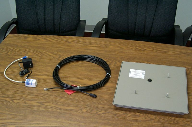
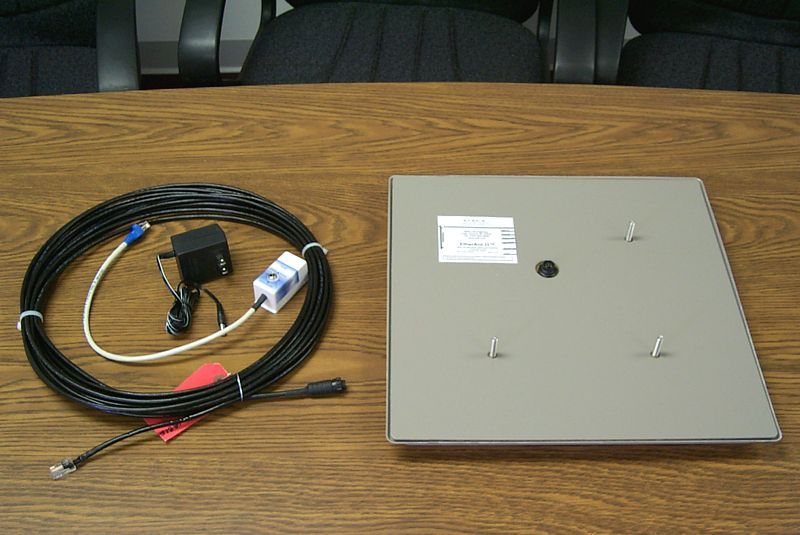
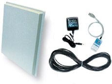
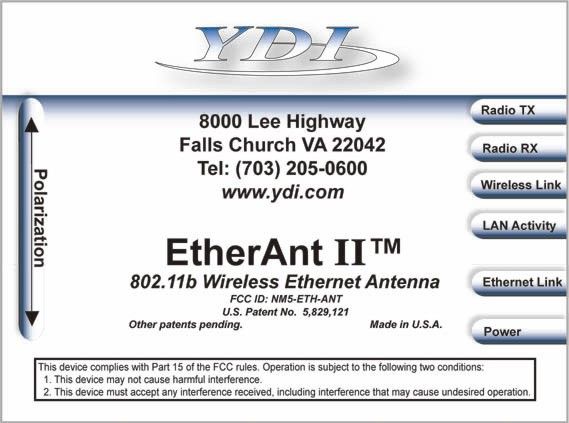
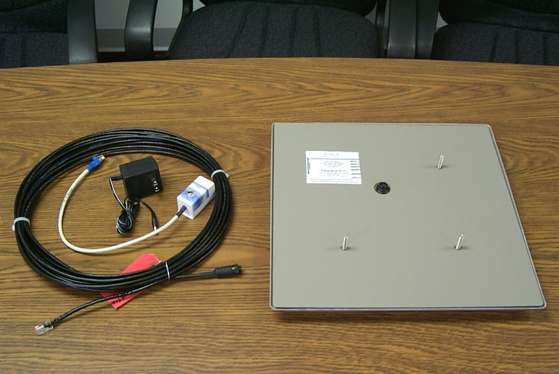
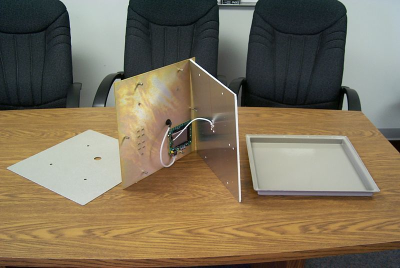
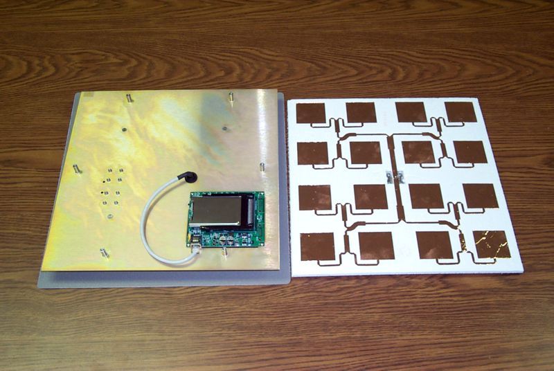
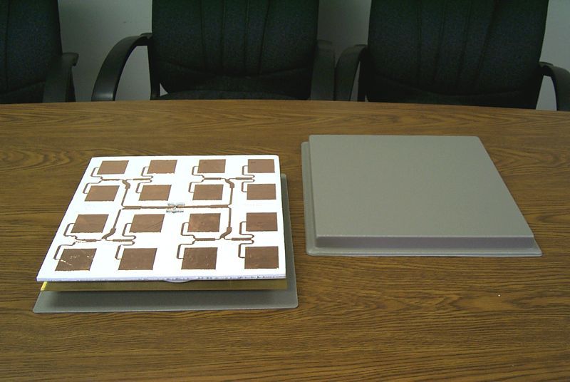
1 2 FCC Notice The Young Design, Inc. wireless Ethernet equipment described herein complies with FCC radiation exposure limits set forth for an uncontrolled environment when installed as directed. The equipment should be installed and operated as fix-mounted antennas such that the main lobe(s) of these antennas are located a minimum of 2 meters between the antenna and all persons during normal operation. This device complies with Part 15 of the FCC rules. Operation is subject to the following two conditions: 1) This device may not cause harmful interference. 2) This device must accept any interference received, including interference that may cause undesired operation. FCC ID NO: NM5-ETH-ANT FCC Notice This antenna/transmitter device must be fixed-mounted on outdoor permanent structures with a separation distance of at least 2 meters from all persons. Users and installers must adhere to the antenna installation instructions and transmitter operating conditions for satisfying RF exposure compliance set forth under Part 15 of the FCC regulations. © 2002 Young Design, Inc. All Rights Reserved. No part or parts of this document may be reproduced, translated, stored in any electronic retrieval system or transmitted, in any form or by any means, electronic, mechanical, photocopied, recorded or otherwise, without the prior written permission of Young Design, Inc. 3 Flat Panel Antenna with Wireless Ethernet Adapter 1.1 Description The YDI Ether-Ant described in this manual is an 18dBi gain flat panel directional antenna with a built-in wireless Ethernet adapter. The equipment is 802.11b WiFi TM compliant. The antenna provides outdoor high- speed wireless connectivity for desktop PCs, laptop computers and routers equipped with a 10BaseT Ethernet port. The antenna offers the simplest, most efficient 2.4 GHz wireless Internet access solution for Ethernet-enabled desktop PCs. It will communicate with any other wireless clients that are 100% WiFi TM compatible. It is ideal for use as a client station device for wireless Internet applications. Built-in voltage regulators allow the antenna to operate from 7– 15VDC sources. A suitable AC adapter designed for 110VAC is included with the antenna kit. 1.2 Configuration Utility Software The Configuration Utility Software (Utility) used with the Ether-Ant can be installed on a PC or workstation running Windows. The utility is a Graphical User Interface (GUI) program that allows the user to locally or remotely display units running on the local network and view/modify configurations for those units. The software communicates with the antenna using a non-routable protocol, so the unit must be accessible on the same subnet as the computer that has the installed Utility. Using Windows, the Utility installs from a CD-Rom included in the unit. When the user executes the Utility setup file, the software begins the installation program taking the user through a step-by-step process. 1.3 Configuring the Ether-Ant Use the Configuration Utility to configure the Ether-Ant. The Main Configuration screen for any selected device contains settings that can be configured for Radio and Network interfaces. 4 The Radio settings initialize the antenna’s built-in radio and configure the new device to join a designated wireless network. The Network settings connect the new device to the existing Ethernet LAN. The subnet and IP addresses of the network the user intends to connect to are required for this configuration. 1.4 Installation FCC NOTICE: This antenna/transmitter device must be fixed-mounted on outdoor permanent structures with a separation distance of at least 2 meters from all persons. Users and installers must adhere to the antenna installation instructions and transmitter operating conditions for satisfying RF exposure compliance set forth under Part 15 of the FCC regulations. The YDI Ether-Ant has a built-in radio so that professional antenna installation is not required. Because the antenna uses the PC’s existing Ethernet interface, there are no drivers to install for this device. There are no radio frequency (RF) cables because the radio device is built right into the antenna. The antenna is intended to be a pole or wall- mounted outdoor installation. The Ether-Ant installation procedures are described below. • Connect the Ethernet cable included in the antenna kit to the flat panel antenna using the 6-pin N-male connector. Up to 200 feet can be used. • Use brackets and screws to mount the flat panel to the antenna mast. • Connect the Ethernet cable attached to the antenna to the Cat 5 DC Power Injector at the RJ-45 port labeled “To ANT.” • Connect the Ethernet cable labeled “To PC or ROUTER” extending from the Cat 5 DC Power Injector to your computer, router or optional lightning protector. • Plug the AC Adapter into an AC outlet and connect to the jack on the Cat 5 DC Power Injector labeled “DC Power.” • Ensure that the Power and Ethernet LEDs are lit on the back of the Ether-Ant. A steady green Power LED indicates that power is being supplied to the antenna. The interface LEDs show a steady green light when there is a valid link. A flickering amber light indicates activity on the Ethernet interface. 1.5 Aiming the Antenna and Checking Signal Strength The most important issue regarding installing the YDI Ether-Ant is to determine the optimal positioning for the device and to ensure clear line of sight to the base station. The Configuration Utility has built-in signal strength indicators, which can be used to aim the antenna properly.
Cover Letter(s)
Mike Foster Director of Engineering Young Design, Inc. 8000 Lee Highway Falls Church, VA 22042 (703) 205-0073 [email protected] Federal Communications Commission Authorization and Evaluation Division Confidentiality Request FCC ID: NM5-ETH-ANT Pursuant to Sections 0.457 and 0.459 of the Commission’s Rules, the Applicant hereby requests confidential treatment of information accompanying this Application as outlined below: For the Agere Wireless LAN card used within the device: Schematics Block Diagram Operational Descriptions The above materials contain trade secrets and proprietary information not customarily released to the public. The public disclosure of these matters might be harmful to the Applicant and provide unjustified benefits to its competitors. The Applicant understands that pursuant to Rule 0.457, disclosure of this Application and all accompanying documentation will not be made before the date of the Grant for this application. Regards, Mike Foster Director of Engineering, Young Design, Inc. 15 April 2002
Test Report
Y Y O O U U N N G G D D E E S S I I G G N N , , I I N N C C . . F F C C C C I I N N F F O O R R M M A A T T I I O O N N FCC ID: NM5-ETH-ANTPage 2 of 42 R R R F F F M M M e e e a a a s s s u u u r r r e e e m m m e e e n n n t t t R R R e e e p p p o o o r r r t t t P P P r r r e e e p p p a a a r r r e e e d d d b b b y y y : : : N N N a a a t t t i i i o o o n n n a a a l l l C C C e e e r r r t t t i i i f f f i i i c c c a a a t t t i i i o o o n n n L L L a a a b b b o o o r r r a a a t t t o o o r r r y y y 8370 Court Avenue, Suite B-1 Ellicott City, Maryland 21043 (410) 461-5548 I I I n n n S S S u u u p p p p p p o o o r r r t t t o o o f f f : : : F F F o o o r r r : : : Young Design, Inc. 8000 Lee Highway Arlington, VA 22042 Model: Ethernet Transmitter Antenna FCCID: NM5-ETH-ANT Demonstration of Compliance with FCC Rules Part 15.247 No part of this report may be reproduced without written approval of National Certification Laboratory March 10, 2002 FCC APPLICATION FOR CERTIFICATION FCC ID: NM5-ETH-ANTPage 3 of 42 TABLE OF CONTENTS 1.0General Information.................................................................................................................................5 1.1Summary.............................................................................................................................................5 1.2Test Methodology...................................................................................................................................5 1.3Test Facility.............................................................................................................................................5 2.0Description of Equipment Under Test (EUT).........................................................................................6 2.1EMI Countermeasure..............................................................................................................................7 4.0Test Configuration For Antenna Terminal Conducted.........................................................................8 4.1Peak Power Test Results.........................................................................................................................9 4.26 dB Emission Bandwidth Test Results................................................................................................10 4.2.16 dB Bandwidth Emissions (100 kHz Res. BW) Low Channel Plot............................................11 4.2.26 dB Bandwidth Emissions (100 kHz Res. BW) Mid Channel Plot.............................................12 4.2.36 dB Bandwidth Emissions (100 kHz Res. BW) High Channel Plot............................................13 4.3RF Antenna Conducted Spurious/Harmonics Emissions......................................................................14 4.3.1FCC Part 15.247(c) Conducted Spurious, 2412 MHz Frequency Of Carrier...............................15 4.3.2FCC Part 15.247(c) Conducted Spurious, 2437 MHz Frequency of Carrier................................16 4.3.3FCC Part 15.247(c) Conducted Spurious,2462 MHz Frequency of Carrier.................................17 4.4Conducted Bandedge Emissions Test Results......................................................................................18 4.4.1Low Channel Conducted Bandedge Emissions Plot.....................................................................18 4.4.2High Channel Conducted Bandedge Emissions Plot....................................................................19 4.5Power Spectral Density.........................................................................................................................20 4.5.1Power Spectral Density Low Channel Plot...................................................................................21 4.5.2Power Spectral Density Mid Channel Plot....................................................................................22 4.5.3Power Spectral Density High Channel Plot..................................................................................23 5.0Test Configuration For Conducted And Radiated Emissions............................................................24 6.0A.C. Conducted Emissions Scheme.......................................................................................................25 6.1AC Conducted Emissions Data Table...................................................................................................26 7.0Radiated Emissions Scheme...................................................................................................................27 FCC ID: NM5-ETH-ANTPage 4 of 42 7.1Low Channel Radiated Emissions Data Table......................................................................................28 7.2Mid Channel Radiated Emissions Data Table.......................................................................................29 7.3High Channel Radiated Emissions Data Table.....................................................................................30 7.4High Channel Bandedge Radiated Emissions Data Table....................................................................31 7.5Low Channel Bandedge Radiated Emissions Data Table.....................................................................31 8.0RF Exposure Statement..........................................................................................................................33 TABLES Table 1EUT Accessories..............................................................................................................34 Table 2Support Equipment.........................................................................................................36 Table 3Measurement Equipment Used......................................................................................37 EXHIBITS Exhibit 1Measurement Photographs............................................................................................38 Exhibit 1.1AC Conduct…
Text truncated - open the document above for the full version.
Test Setup Photos
FCC ID: NM5-ETH-ANTPage 38 of 42 E E E X X X H H H I I I B B B I I I T T T 1 1 1 . . . 1 1 1 A A A C C C C C C O O O N N N D D D U U U C C C T T T E E E D D D E E E M M M I I I S S S S S S I I I O O O N N N S S S P P P H H H O O O T T T O O O G G G R R R A A A P P P H H H S S S FCC ID: NM5-ETH-ANTPage 39 of 42 E E E X X X H H H I I I B B B I I I T T T 1 1 1 . . . 1 1 1 A A A C C C C C C O O O N N N D D D U U U C C C T T T E E E D D D E E E M M M I I I S S S S S S I I I O O O N N N S S S P P P H H H O O O T T T O O O G G G R R R A A A P P P H H H S S S FCC ID: NM5-ETH-ANTPage 40 of 42 E E E X X X H H H I I I B B B I I I T T T 1 1 1 . . . 2 2 2 R R R A A A D D D I I I A A A T T T E E E D D D E E E M M M I I I S S S S S S I I I O O O N N N S S S P P P H H H O O O T T T O O O G G G R R R A A A P P P H H H S S S
Contact Information
Applicant
John Hutchings(Product Integrity Manager)
Test Firm
National Certification LaboratoryBrian Haghtalab
Technical Specifications
| # | Rule Parts | Frequency Range | Power Output |
|---|---|---|---|
| 1 | 15C | 2.41 GHz - 2.46 GHz | 31.60 mW |
Other Applications from YDI Wireless

NM5-MB-49-HP
Apr 12, 2005Point to Point Wireless Bridge
Equipment Class
TNB - Licensed Non-Broadcast Station Transmitter
NM5-MB-49
Jul 27, 2004Wireless Network Bridge
Equipment Class
TNB - Licensed Non-Broadcast Station Transmitter
NM5-MB-HP
Jul 07, 2004Outdoor Transmitter
Equipment Class
DTS - Digital Transmission System
NM5-MB-ST
Jun 29, 2004Point-to-Point Transmitter
Equipment Class
NII - Unlicensed National Information Infrastructure TX
NM5-CX-DS3-ETH-24
Mar 14, 2004Point to Point 24GHz Microwave Radio
Equipment Class
DXX - Part 15 Low Power Communication Device Transmitter