NM5-MR-12.4GHz INDOOR SIGNAL BOOSTER
YDI Wireless
Click to zoom
Application Details
- Equipment Class
- DSS - Part 15 Spread Spectrum Transmitter
- Date of Grant
- Aug 20, 2003
- Application Purpose
- Original Equipment
- Date of Application
- Aug 20, 2003
- Equipment Note
- 2.4GHz INDOOR SIGNAL BOOSTER
- Frequency Range
- 2400.00000000 - 2483.50000000
- Company
- YDI Wireless
- Country
- United States
Documents & Files
Document Text
Text extracted from the exhibit documents filed with the FCC. Open a document above to read the original.
Users Manual
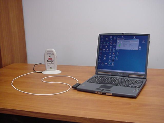
Max Ranger Quick Start Guide Figure 2 – Max Ranger LEDs Introduction The Max Ranger is an antenna with an integrated bi- directional amplifier used to extend the indoor range of 802.11b Wireless LAN cards. The Max Ranger is designed to be used with YDI/Agere PCMCIA WLAN cards that can be inserted into any suitable device such as an Access Point, YDI Ethernet Converter (EC), or even a laptop computer. It is easy to install and ready to work “right out of the box”. The internal antenna is horizontally polarized for optimum RF connection to other WLAN cards which typically are also horizontally polarized. It features over 300 mW (+25 dBm) of transmit power (EIRP). It is FCC Part 15 Certified for license-free operation with our Sidekick and Sapphire WLAN cards, and is capable to work in a temperature range of 0°C to +50°C. Max Ranger Kit Contents Installation 1. Antenna with integrated bi-directional amplifier and RF cable terminated in antenna connector for the YDI/Agere WLAN card The Max Ranger radio unit can be placed near the computer or device on a tabletop. 2. YDI Sidekick Wireless LAN card 1. Remove the small black plastic cap from the proprietary antenna jack of the WLAN card with your finger nail or a small screwdriver. 3. 110/220 VAC to 5 VDC wall mount power supply Figure 1 – Max Ranger Kit 2. Plug the RF cable that is attached at the bottom of the Max Ranger to the proprietary antenna jack on the WLAN card as shown on figure 3. CAUTION: The antenna connector is a tight push-on fit. Figure 3 – Connecting the Max Ranger to the WLAN Card Warning: Insert the WLAN card into the appropriate slot making sure that: 1) The WLAN Card is upside (brand label must be visible) 2) It slides smoothly across the internal rails of the slot 3) It is gently pushed all the way in Proprietary Antenna Connector. It must be inserted straight into the WLAN card. Warning: Insert this end into the WLAN card gently . Do not twist when removing it or you may damage the connector! Insert into a compatible Access Point, YDI EC, or Laptop computer LEDs Two LEDs are present on the front of the Max Ranger (see Figure 2): • The Red LED flashes when the Max Ranger transmits data • The Green LED indicates that the Max Ranger is in receive mode 3. Plug the DC power connector into the jack at the bottom of the Max Ranger as shown on Figure 4. Push the cable into the notch in the base to insure the Max Ranger is stable on the tabletop. 4. Plug the power supply into a standard wall outlet. Red LED (Tx) Green LED (Rx) 2 1 3 MNL-500120-001 – Rev 1.1 1 August 2003 Max Ranger Quick Start Guide August 2003 2 MNL-500120-001 – Rev 1.1 Figure 4 – Plugging the DC Power Connector into the Bottom Jack of the Max Ranger Technical Support Your primary source of assistance is the dealer from which you purchased this product. The YDI support staff should only be contacted directly if you purchased this product directly from YDI. NOTE: Before you contact Technical Support, please make sure that you have read and thoroughly understood all instructions outlined on this manual. YDI Wireless Tel.: 703-205-0600 8000 Lee Highway Fax: 703-205-0610 Falls Church, VA 22042 E-mail: [email protected] USA www.ydi.com The latest software and User’s Manuals can also be found at: http://www.ydi.com/support/downloads.php Operation http://www.ydi.com/support/documents.php 1. To find the best position for your Max Ranger, YDI recommends to use the Signal Strength Indicator found on the Link Test screen of the Wireless Client Manager for your WLAN card. You can also use the YDI Client Manager for EC. For a detailed explanation on how to use each software, please refer to the User’s Manual of your specific product. FCC NOTICE This antenna/transmitter device complies with FCC radiation exposure limits set forth for an uncontrolled environment when installed as directed. The antenna used for this transmitter must be installed and operated with a minimum separation distance of at least 20 centimeters (8 inches) from all persons during normal operation, and must not be co-located or operating in conjunction with any other antenna or transmitter. Users and installers must adhere to the antenna installation instructions and transmitter operating conditions in order to comply with the FCC’s RF exposure requirements. 2. Aim the Max Ranger by turning it back and forth until the maximum signal strength is reached. Antenna Patterns The Max Ranger boosts the signal the most in the front and back directions (Figure 5a) as well as out of the top (Figure 5b). The weakest signal will be at the bottom and sides. This device complies with part 15 of the FCC rules. Operation is subject to the following two conditions: Figure 5a Figure 5b Top View Showing the Side View Showing the Strongest Signal Maximum Coverage Area Facing the Flat Parts Out of the Top and Sides (1) This device may not cause harmful interference, and (2) This device must accept any interference received, including interference that may cause undesired operation. NOTE: The manufacturer is not responsible for any radio or TV interference caused by unauthorized modifications to this equipment. Such modifications could void the user's authority to operate the equipment. The Max Ranger is certified by the FCC for use with the PC24E-11-FC/R series of YDI Wireless LAN cards made by Agere. To see all our FCC certified systems, please visit: http://www.ydi.com/deployinfo/fcc-info.php
Users Manual
Max Ranger Quick Start Guide MNL-500120-001 – Rev 1.5 1 January 2004 Introduction The Max Ranger is an antenna with an integrated bi- directional amplifier used to extend the indoor range of 802.11b Wireless LAN cards. The Max Ranger is designed to be used with the Agere-based PCMCIA WLAN cards provided by YDI Wireless which can be inserted into any suitable device such as an Access Point, YDI Ethernet Converter (EC), or even a laptop computer. It is easy to install and ready to work “right out of the box”. The internal antenna is horizontally polarized for optimum RF connection to other WLAN cards which typically are also horizontally polarized. It features over 300 mW (+25 dBm) of transmit power (EIRP). It is FCC Part 15 Certified for license-free operation with all of our WLAN cards, and is capable to work in a temperature range from 0°C to +50°C. Max Ranger Kit Contents 1. Antenna with integrated bi-directional amplifier and RF cable terminated in antenna connector for the YDI/Agere WLAN card 2. YDI Sapphire Wireless LAN card 3. YDI CD ROM with windows-based software and documentation 4. 110/220 VAC to 5 VDC wall mount power supply Figure 1 – Max Ranger Kit LEDs Two LEDs are present on the front of the Max Ranger (see Figure 2): • The Red LED flashes when the Max Ranger transmits data • The Green LED indicates that the Max Ranger is in receive mode Figure 2 – Max Ranger LEDs Installation The Max Ranger radio unit can be placed near the computer or device on a tabletop. 1. Remove the small black plastic cap from the proprietary antenna jack of the WLAN card with your finger nail or a small screwdriver. 2. Plug the RF cable that is attached at the bottom of the Max Ranger to the proprietary antenna jack on the WLAN card as shown on figure 3. CAUTION: The antenna connector is a tight push-on fit. Figure 3 – Connecting the Max Ranger to the WLAN Card Warning: Insert the WLAN card into the appropriate slot making sure that: 1) The WLAN Card is upside (brand label must be visible) 2) It slides smoothly across the internal rails of the slot 3) It is gently pushed all the way in Proprietary Antenna Connector. It must be inserted straight into the WLAN card. Warning: Insert this end into the WLAN card gently . Do not twist when removing it or you may damage the connector! Insert into a compatible Access Point, YDI EC, or Laptop computer 3. Plug the DC power connector into the jack at the bottom of the Max Ranger as shown on Figure 4. Push the cable into the notch in the base to insure the Max Ranger is stable on the tabletop. 4. Plug the power supply into a standard wall outlet. 1 3 Red LED (Tx) Green LED (Rx) 2 4 Max Ranger Quick Start Guide January 2004 2 MNL-500120-001 – Rev 1.5 Figure 4 – Plugging the DC Power Connector into the Bottom Jack of the Max Ranger Operation 1. To find the best position for your Max Ranger, YDI recommends to use the Signal Strength Indicator found on the Link Test screen of the Wireless Client Manager for your WLAN card. You can also use the YDI Client Manager for EC. Both programs can be found on your YDI CD ROM included with your Max Ranger. For a detailed explanation on how to use each software, please refer to the User’s Manual of your specific product. 2. Aim the Max Ranger by turning it back and forth until the maximum signal strength is reached. Antenna Patterns The Max Ranger boosts the signal the most in the front and back directions (Figure 5a) as well as out of the top (Figure 5b). The weakest signal will be at the bottom and sides. Figure 5a Figure 5b Top View Showing the Side View Showing the Strongest Signal Maximum Coverage Area Facing the Flat Parts Out of the Top and Sides Technical Support Your primary source of assistance is the dealer from which you purchased this product. The YDI support staff should only be contacted directly if you purchased this product directly from YDI. NOTE: Before you contact Technical Support, please make sure that you have read and thoroughly understood all instructions outlined on this manual. YDI Wireless Tel.: 703-205-0600 8000 Lee Highway Fax: 703-205-0610 Falls Church, VA 22042 E-mail: [email protected] USA www.ydi.com The latest software and User’s Manuals can also be found at: http://www.ydi.com/support/downloads.php http://www.ydi.com/support/documents.php FCC NOTICE This antenna/transmitter device complies with FCC radiation exposure limits set forth for an uncontrolled environment when installed as directed. The antenna used for this transmitter must be installed and operated with a minimum separation distance of at least 20 centimeters (8 inches) from all persons during normal operation, and must not be co-located or operating in conjunction with any other antenna or transmitter. Users and installers must adhere to the antenna installation instructions and transmitter operating conditions in order to comply with the FCC’s RF exposure requirements. This device complies with part 15 of the FCC rules. Operation is subject to the following two conditions: (1) This device may not cause harmful interference, and (2) This device must accept any interference received, including interference that may cause undesired operation. NOTE: The manufacturer is not responsible for any radio or TV interference caused by unauthorized modifications to this equipment. Such modifications could void the user's authority to operate the equipment. The Max Ranger is certified by the FCC for use with the Agere-based WLAN cards provided by YDI Wireless. The product is labeled with FCC ID number: NM5-MR-1. To see all our FCC certified systems, please visit: http://www.ydi.com/deployinfo/fcc-info.php
Cover Letter(s)
Correspondence summary for RTs 11788 and 23221 The following FCC interpretation was sent to the applicant regarding the labeling question in item 2 of the RT: "Based on section 15.19(a)(4) and Section 2.925(a) requirements and the fact that the amplifier section of this transmission system has no frequency determining circuitry of its own, the Commission believes that the FCC ID label must be replaced on the intentional radiator (main control unit). If this intentional radiator already bears an FCC ID label because it was approved on its own, that label must either be removed or covered by the new FCC ID label of the transmission system." No response was received from the applicant after this.
External Photos
Internal and External Unit Photographs 7/23/03 Page 2 of 8 YDI Wireless Proprietary All information, including mechanical and electrical designs, described on or otherwise set forth on this document is proprietary and confidential to YDI Wireless and may not be copied or reproduced by any means, or disclosed by the party who receives this document to any other party without prior written permission from YDI Wireless. This document is on loan from YDI Wireless and must be immediately returned on demand. Photograph of EUT – Front view Internal and External Unit Photographs 7/23/03 Page 3 of 8 YDI Wireless Proprietary All information, including mechanical and electrical designs, described on or otherwise set forth on this document is proprietary and confidential to YDI Wireless and may not be copied or reproduced by any means, or disclosed by the party who receives this document to any other party without prior written permission from YDI Wireless. This document is on loan from YDI Wireless and must be immediately returned on demand. Photograph of EUT – Rear view Internal and External Unit Photographs 7/23/03 Page 4 of 8 YDI Wireless Proprietary All information, including mechanical and electrical designs, described on or otherwise set forth on this document is proprietary and confidential to YDI Wireless and may not be copied or reproduced by any means, or disclosed by the party who receives this document to any other party without prior written permission from YDI Wireless. This document is on loan from YDI Wireless and must be immediately returned on demand. Photograph of EUT – Bottom view
ID Label/Location Info
Label and Label Location 7/23/03 2/2 YDI Wireless Proprietary All information, including mechanical and electrical designs, described on or otherwise set forth on this document is proprietary and confidential to YDI Wireless and may not be copied or reproduced by any means, or disclosed by the party who receives this document to any other party without prior written permission from YDI Wireless. This document is on loan from YDI Wireless and must be immediately returned on demand. The label location on the exterior of the Max Ranger is shown in Photograph 2. Photograph 2: Label Location on Exterior of Max Ranger
ID Label/Location Info
Label and Label Location 7/23/03 1/2 YDI Wireless Proprietary All information, including mechanical and electrical designs, described on or otherwise set forth on this document is proprietary and confidential to YDI Wireless and may not be copied or reproduced by any means, or disclosed by the party who receives this document to any other party without prior written permission from YDI Wireless. This document is on loan from YDI Wireless and must be immediately returned on demand. File: YDIWirelessMR-1ID2.doc ID Label/Location Max Ranger MR-1 YDI Wireless Proprietary All information, including mechanical and electrical designs, described on or otherwise set forth on this document is proprietary and confidential to YDI Wireless and may not be copied or reproduced by any means, or disclosed by the party who receives this document to any other party without prior written permission from YDI Wireless. This document is on loan from YDI Wireless and must be immediately returned on demand. The Max Ranger ID Label is required to include the FCC ID and the statement: “This device complies with part 15 of the FCC Rules. Operation is subject to the following two conditions: (1) This device may not cause harmful interference, and (2) this device must accept any interference received, including interference that may cause undesired operation.” In accordance with part 2 section .925 and .926 of the commission’s rules. The label is shown below in Photograph 1. Photograph 1: Max Ranger FCC ID Label
Internal Photos
Internal and External Unit Photographs 7/23/03 Page 6 of 8 YDI Wireless Proprietary All information, including mechanical and electrical designs, described on or otherwise set forth on this document is proprietary and confidential to YDI Wireless and may not be copied or reproduced by any means, or disclosed by the party who receives this document to any other party without prior written permission from YDI Wireless. This document is on loan from YDI Wireless and must be immediately returned on demand. Photograph of EUT – Internal View Copper side Internal and External Unit Photographs 7/23/03 Page 7 of 8 YDI Wireless Proprietary All information, including mechanical and electrical designs, described on or otherwise set forth on this document is proprietary and confidential to YDI Wireless and may not be copied or reproduced by any means, or disclosed by the party who receives this document to any other party without prior written permission from YDI Wireless. This document is on loan from YDI Wireless and must be immediately returned on demand. Photograph of EUT – Internal View Component side
Operational Description
8000 Lee Highway Falls Church VA 22042 Tel: (703) 205-0600 Fax: (703) 205-0610 Sales: 1-888-297-9090 990 Almanor Avenue Sunnyvale, CA 94085 Tel: (408) 617-8150 Fax: (408) 617-8151 Sales: 1-800-664-7060 www.ydi.com Max Ranger Indoor Signal Booster Kit TM 2.4 GHz Antenna with Integrated Amplifier and 802.11b WLAN card Package Includes Antenna with integrated bi-directional amplifier and RF cable terminated in antenna connector for the YDI/Agere WLAN card YDI Sapphire Wireless LAN card YDI CD-ROM with Windows-based software and documentation 110/220 VAC to 5 VDC wall mount power supply The Max Ranger is an antenna with an integrated bi-direc- tional amplifier used to extend the indoor range of 802.11b Wireless LAN cards. The Max Ranger is designed to be used with the Agere-based PCMCIA WLAN cards provided by YDI Wireless which can be inserted into any suitable device such as an Access Point, YDI Ethernet Converter (EC), or even a laptop computer. It is easy to install and ready to work "right out of the box". The internal antenna is horizontally polarized for optimum RF connection to other WLAN cards which typically are also horizontally polarized. It features over 300 mW (+25 dBm) of transmit power (EIRP). It is FCC Part 15 Certified for license-free opera- tion with all of our WLAN cards, and is capable to work in a temperature range from 0°C to +50°C. Description Rev A Feb 2004 Specifications subject to change without notice Key Features Easy to install and configure Extends the indoor range of 802.11b WLAN cards Includes 802.11b Sapphire WLAN card Can be used with any compatible device such as an Access Point, YDI Ethernet Converter (EC), or a lap- top computer Horizontally polarized antenna Transmit power of 300 mW (+25 dBm) EIRP FCC Part 15 Certified for license-free operation Windows-based Wireless Client Manager shows sig- nal, noise and SNR levels Operating temperature range: 0°C to +50°C Note: The Max Ranger is certified by the FCC for use with the Agere-based WLAN Cards provided by YDI Wireless. The product is labeled with FCC ID number: NM5-MR-1 Without Max Ranger With Max Ranger
Parts List/Tune Up Info
The content of this document is " AGERE Systems ’ intellectual property" and is the property of AGERE Systems. It is to be treated as strictly confidential and is not to be disclosed, reproduced or used, except as authorised in writing by AGERE Systems in connection with the manufacture, maintenance and use of the AGERE Systems equipment to which it pertains. Copyright © 2001 Agere Systems . CHANGES: NEXT ASSY (A) New SHEET 2 3 4 5 6 7 8 9 10 11 1213 14 15 SIZE A4 A4 A3 A3 REV. A A A A A REVDR-NUMBER INIT. DATE AGERE SYSTEMS NEDERLAND B.V. DESIGNER: Henrie Kerver DATE: June 2001 UNIT : ORINOCO/IEEE PCMCIA type 2 EXTENDED RUBY SUPSD.BY: SUPSDS: NAME : BOARD ASSY SHEET: 1 OF 5 SCALE: COMCODE: DOC. NO.: 017758 ITEM PART/DWG # REQ'D NAME AND DESCRIPTION NOTES 1 000038 1 MIC2920A-3.3BS, AIC, MICREL, MIC2920A-3.3BS U20 2 001748 3 CAP, CAP, 1uF, MURATA, GRM40X5R105K10 C33 C62 C91 3 001749 1 CAP, CAP, 2.2uF, MURATA, GRM40Y5V225Z10 C60 4 002051 1 RES, RES, 0, KOA, RK73Z1JTD R408 5 002052 1 RES, RES, 1.00, KOA, RK73H1JT1R00F R101 6 002236 1 RES, RES, 82.5, KOA, RK73H1JT82R5F R77 7 002671 1 CAP, CAP, 8.2pF, MURATA, GRM39COG8R2C50 C400 8 003244 2 RES, RES, 100, KOA, RK73H1ETP1000F R304 R305 9 0 10 003283 1 RES, RES, 255, KOA, RK73H1ETP2550F R111 11 003290 6 RES, RES, 301, KOA, RK73H1ETP3010F R400 R401 R403 R404 R405 R406 12 003296 1 RES, RES, 348, KOA, RK73H1ETP3480F R114 13 003319 4 RES, RES, 604, KOA, RK73H1ETP6040F R1 R2 R82 R83 14 003340 14 RES, RES, 1.00k, KOA, RK73H1ETP1001F R10 R18 R20 R32 R35 R53 R54 R56 R108 R116 R413 R414 R415 R416 15 003357 3 RES, RES, 1.50k, KOA, RK73H1ETP1501F R43 R68 R79 16 003369 6 RES, RES, 2.00k, KOA, RK73H1ETP2001F R24 R52 R70 R90 R92 R402 17 003390 1 RES, RES, 3.32k, KOA, RK73H1ETP3321F R42 18 003428 1 RES, RES, 8.25k, KOA, RK73H1ETP8251F R17 19 003436 10 RES, RES, 10.0k, KOA, RK73H1ETP1002F R5 R8 R21 R29 R51 R72 R80 R102 R105 R115 20 003459 1 RES, RES, 17.4k, KOA, RK73H1ETP1742F R50 21 003465 7 RES, RES, 20.0k, KOA, RK73H1ETP2002F R12 R13 R14 R15 R89 R94 R103 22 003485 6 RES, RES, 32.4k, KOA, RK73H1ETP3242F R91 R93 R100 R104 R107 R112 23 003496 1 RES, RES, 42.2k, KOA, RK73H1ETP4222F R95 24 003503 1 RES, RES, 49.9k, KOA, RK73H1ETP4992F R23 25 003532 4 RES, RES, 100k, KOA, RK73H1ETP1003F R27 R88 R106 R113 26 003651 1 CAP, CAP, 0.5pF, MURATA, GRM36COG0R5C50 C311 27 003653 9 CAP, CAP, 1.0pF, MURATA, GRM36COG1R0C50 C68 C303 C436 C437 C438 C439 C440 C441 C443 28 003671 24 CAP, CAP, 8.2pF, MURATA, GRM36COG8R2C50 C3 C23 C24 C25 C26 C38 C41 C43 C50 C51 C52 C53 C54 C55 C66 C71 C74 C75 C76 C95 C306 C313 C401 C442 29 003675 34 CAP, CAP, 12pF, MURATA, GRM36COG120J50 C402 C403 C404 C405 C406 C407 C408 C409 C410 C411 C412 C413 C414 C415 C416 C417 C418 C419 C420 C421 C422 C423 C424 C425 C426 C427 C428 AGERE SYSTEMS NEDERLAND B.V. 017758 UNIT : ORINOCO/IEEE PCMCIA type 2 EXTENDED RUBY SCALE: REV :A NAME : BOARD ASSY SHEET 2 OF 5 ITEM PART/DWG # REQ'D NAME AND DESCRIPTION NOTES C429 C430 C431 C432 C433 C434 C435 30 003689 4 CAP, CAP, 47pF, MURATA, GRM36COG470J50 C21 C35 C36 C47 31 003703 2 CAP, CAP, 180pF, MURATA, GRM36COH181J25 C22 C49 32 003714 12 CAP, CAP, 1nF, MURATA, GRM36X7R102K50 C44 C67 C72 C73 C79 C80 C83 C85 C87 C92 C94 C97 33 003727 2 CAP, CAP, 15nF, MURATA, GRM36Y5V153Z50 C84 C96 34 003731 26 CAP, CAP, 100nF, MURATA, GRM36Y5V104Z16 C6 C7 C2 C1 C9 C10 C11 C14 C18 C28 C29 C30 C31 C32 C39 C56 C57 C58 C59 C69 C70 C77 C78 C81 C86 C89 35 003852 1 IND, IND, 1.2nH, TOKO, LL1005-FH1N2S L18 36 003855 5 IND, IND, 2.2nH, TOKO, LL1005-FH2N2S L1 L2 L7 L8 L33 37 003857 18 IND, IND, 3.3nH, TOKO, LL1005-FH3N3K L19 L20 L21 L22 L23 L24 L25 L26 L27 L28 L29 L30 L31 L32 U24 U25 U26 U27 38 003859 1 IND, IND, 4.7nH, TOKO, LL1005-FH4N7K L15 39 003860 2 IND, IND, 5.6nH, TOKO, LL1005-FH5N6K L16 L17 40 003864 7 IND, IND, 12nH, TOKO, LL1005-FH12NK L3 L9 L10 L11 L12 L13 L14 41 005051 10 RES, RES, 0, KOA, RM73Z1ETD R3 R11 R31 R33 R55 R62 R64 R78 R306 R308 42 005059 2 RES, RES, 2.0, KOA, RM73B1ETP2R0J R22 R40 43 005076 4 RES, RES, 10, KOA, RM73B1ETP10RJ R49 R57 R109 R412 44 005083 3 RES, RES, 20, KOA, RM73B1ETP20RJ R63 R98 R99 45 0 46 005093 2 RES, RES, 51, KOA, RM73B1ETP51RJ R81 R110 47 005107 1 RES, RES, 200k, KOA, RM73B1ETP2003J R34 48 005125 1 RES, RES, 1.0, KOA, RK73H2A1R0F R71 49 005139 1 RES, RES, 3.9, KOA, RK73H2A3R9F R69 50 010003 1 BFP420, TRANSISTOR, SIEMENS, Q62702-F1591 Q3 51 010005 1 SI2301DS, TRANSISTOR, SILICONIX, (TEMIC) U21 52 010009 1 BFP450, TRANSISTOR, SIEMENS, Q62702-F1590 Q8 53 010004 1 MA-LC22.000MHz, AIC, USI, MA-LC22.000MHz U15 54 010010 1 74LVC00PW, DIC U7 55 010011 2 BC847BW, TRANSISTOR, PHILIPS, BC847BW Q2 Q7 56 010016 2 BCV62, TRANSISTOR, PHILIPS, BCV62B Q4 Q5 57 010017 1 TLV431ACDBV5, DIODE, TEXAS, TLV431ACDBV5 D8 58 010018 1 RF_CONN_INBOARD, CONN, RADIALL, R299.794.000 J400 59 010020 2 LGM670_K, DIODE, SIEMENS, Q62703-Q3394 D400 D401 60 010021 1 BAR64_03W, DIODE, SIEMENS, BAR64-03W D4 61 010023 1 LFJ30_03B2450BA100, AIC, MURATA, LFJ30_03B2450BA100 U6 62 010202 1 emi_fil, CAP, NFM61R 4.7nF, MURATA, NFM61R30T472 LC1 63 010204 1 BAR63_03W, DIODE, SIEMENS, BAR63-03W D7 64 010206 2 MIC5205, AIC, MICREL, MIC5205BM5 U14 U19 65 010334 1 BU4S71, MISC, ROHM, BU4S71 U12 66 010464 1 HSMS2852, DIODE, HP, HSMS2852 D9 AGERE SYSTEMS NEDERLAND B.V. 017758 UNIT : ORINOCO/IEEE PCMCIA type 2 EXTENDED RUBY SCALE: REV :A NAME : BOARD ASSY SHEET 3 OF 5 ITEM PART/DWG # REQ'D NAME AND DESCRIPTION NOTES 67 010570 2 LP62S1024, DIC, ELITEMT, LP62S1024 U4 U10 68 010827 1 HERMES, DIC, LUCENT, HERMES U11 69 011276 2 IND, IND, BLM11B222, MURATA, BLM11B222 L5 L6 70 013014 1 W4050, AIC, AGERE, W4050 U5 71 013018 1 OPA337, AIC, BURR-BROWN, OPA337EA U22 72 015154 1 THESEUS_HS2N, DIC, AGERE, N4080SV2LS U17 73 015243 1 SST39VF010, DIC, SST, SST39VF010-90-4C-WH U9 74 015305 9 CAP, CAP, 10uF, MURATA, GRM42_6Y5V106Z10 C13 C16 C17 C20 C40 C48 C61 C63 C90 75 016551 1 MBR0520L, DIODE, FAIRCHILD, MBR0520L D402 76 016552 1 LM2766, AIC, NATIONAL SEMICOM, LM2766M6 U16 77 017132 1 CON_68_POLIG, CONN, FCI, 56459-004 J…
Text truncated - open the document above for the full version.
Test Report
APPLICANT: YDI WIRELESS FCC ID: NM5-MR-1 REPORT #: Y/Young_NM5\774ZUT3\774ZUT3TestReport.doc TABLE OF CONTENTS APPLICANT: YDI WIRELESS FCC ID: NM5-MR-1 TABLE OF CONTENTS FOR A DIRECT SEQUENCE SPREAD SPECTRUM TEST REPORT CONTAINING: PAGE 1.............LIST OF TEST EQUIPMENT PAGE 2.............TEST PROCEDURES PAGE 3.............PRODUCT DESCRIPTION PAGE 4-5...........POWERLINE CONDUCTED INTERFERENCE PAGE 6.............6 dB BANDWIDTH TEST DATA PAGE 7.............RF OUPUT POWER PAGE 8.............SPURIOUS EMISSIONS AT ANTENNA TERMINALS DATA PAGE 9-10..........RADIATION INTERFERENCE TEST DATA PAGE 11............METHOD OF MEASURING RADIATED SPURIOUS EMISS. PAGE 12-15.........RADIATED SPURIOUS EMISSIONS INTO ADJACENT RESTRICTED BANDS PAGE 16............POWER SPECTRAL DENSITY PAGE 17............MPE CALCULATION EXHIBIT ATTACHMENTS: EXHIBIT 1..........REQUEST FOR CONFIDENTIALITY LETTER EXHIBIT 2..........BLOCK DIAGRAM EXHIBIT 3..........SCHEMATIC EXHIBIT 4..........USERS MANUAL EXHIBIT 5..........LABEL SAMPLE EXHIBIT 6..........LABEL LOCATION EXHIBIT 7..........EXTERNAL PHOTOGRAPHS EXHIBIT 8..........INTERNAL PHOTOGRAPHS EXHIBIT 9..........OPERATIONAL DESCRIPTION EXHIBIT 10.........TEST SET UP PHOTOGRAPH APPLICANT: YDI WIRELESS FCC ID: NM5-MR-1 REPORT #: Y/Young_NM5\774ZUT3\774ZUT3TestReport.doc Page 1 of 17 EMC Equipment List Device Manufacturer Model Serial Number Cal/Char Date Due Date 3-Meter OATS TEI N/A N/A Listed 1/13/03 1/13/06 Biconnical Antenna Eaton 94455-1 1057 CAL 3/18/03 3/18/05 Biconnical Antenna Eaton 94455-1 1096 CAL 10/1/01 10/1/03 Biconnical Antenna Electro-Metrics BIA-25 1171 CAL 4/26/01 4/26/03 Double-Ridged Horn Antenna Electro-Metrics RGA-180 2319 CAL 2/17/03 2/17/05 LISN Electro-Metrics ANS-25/2 2604 CAL 10/9/01 10/9/03 LISN Electro-Metrics EM-7820 2682 CAL 3/12/03 3/12/05 Log-Periodic Antenna Eaton 96005 1243 CAL 5/8/03 5/8/05 Log-Periodic Antenna Electro-Metrics EM-6950 632 CHAR 10/15/01 10/15/03 Log-Periodic Antenna Electro-Metrics LPA-25 1122 CAL 10/2/01 10/2/03 Log-Periodic Antenna Electro-Metrics LPA-30 409 CAL 3/4/03 3/4/05 Peak Power Meter HP 8900C 2131A00545 CAL 7/2/03 7/2/05 Power Meter HP 432A 1141A07655 CAL 4/15/03 4/15/05 Silver Tower Preamplifier HP 8449B 3008A01075 CHAR 1/28/02 1/28/04 Silver Tower Quasi-Peak Adapter HP 85650A 3303A01844 CAL 10/14/02 10/14/04 Silver Tower RF Preselector HP 85685A 2620A00294 CAL 10/14/02 10/14/04 Silver Tower Spectrum Analyzer HP 8566B Opt 462 3552A22064 3638A08608 CAL 10/14/02 10/14/04 Tan Tower Preamplifier HP 8449B-H02 3008A00372 CHAR 3/4/01 3/4/03 Tan Tower Quasi-Peak Adapter HP 85650A 3303A01690 CAL 8/31/01 8/31/03 Tan Tower RF Preselector HP 85685A 3221A01400 CAL 8/31/01 8/31/03 Tan Tower Spectrum Analyzer HP 8566B Opt 462 3138A07786 3144A20661 CAL 8/31/01 8/31/03 3/10-Meter OATS TEI N/A N/A Listed 3/26/01 3/26/04 APPLICANT: YDI WIRELESS FCC ID: NM5-MR-1 REPORT #: Y/Young_NM5\774ZUT3\774ZUT3TestReport.doc Page 2 of 17 TEST PROCEDURE GENERAL: This report shall NOT be reproduced except in full without the written approval of TIMCO ENGINEERING, INC. Shielded interface cables were used in all cases except for cables connecting to the telephone line and the power cords. A test program was run which simulated a normal data transmission on a network. POWER LINE CONDUCTED INTERFERENCE: The procedure used was ANSI STANDARD C63.4-1992 using a 50uH LISN. Both lines were observed with the UUT transmitting. The bandwidth of the spectrum analyzer was 10kHz with an appropriate sweep speed. The ambient temperature of the UUT was 78°F with a humidity of 55%. BANDWIDTH 6.0 dB: The measurements were made with the spectrum analyzer's resolution bandwidth (RBW)=1.0MHz and the video bandwidth (VBW) =3.0MHz and the span set as shown on plot. POWER OUTPUT: The RF power output was measured at the antenna feed point using a Agilent 8900C peak power meter. ANTENNA CONDUCTED EMISSIONS: The RBW=100 kHz, VBW=300 kHz and the span set to 20 MHz and the spectrum was scanned from 30 MHz to the 10 th Harmonic of the fundamental. RADIATION INTERFERENCE: The test procedure used was ANSI STANDARD C63.4-1992 using an Agilent spectrum analyzer with a pre-selector. The bandwidth (RBW) of the spectrum analyzer was 100 kHz up to 1 GHz and 1 MHz above 1GHz with an appropriate sweep speed. The VBW above 1 GHz was = 3 MHz. The analyzer was calibrated in dB above a microvolt at the output of the antenna. The ambient temperature of the UUT was 85°F with a humidity of 57%. APPLICANT: YDI WIRELESS FCC ID: NM5-MR-1 REPORT #: Y/Young_NM5\774ZUT3\774ZUT3TestReport.doc Page 3 of 17 PRODUCT DESCRIPTION: The NM5 -MR-1 is a direct sequence spread spectrum radio that operates in the 2400 to 2483.5 MHz band. APPLICANT: YDI WIRELESS FCC ID: NM5-MR-1 REPORT #: Y/Young_NM5\774ZUT3\774ZUT3TestReport.doc Page 4 of 17 APPLICANT: YDI WIRELESS FCC ID: NM5-MR-1 NAME OF TEST: POWER LINE CONDUCTED INTERFERENCE RULES PART NO.: 15.107(a) REQUIREMENTS: QUASI-PEAK AVERAGE .15 – 0.5 MHz 66-56 dBuV 56-46 dBuV 0.5 – 5.0 56 46 5.0 – 30. 60 50 TEST PROCEDURE: ANSI STANDARD C63.4-1992. The spectrum was scanned from 0.15 to 30 MHz. TEST DATA: POWER LINE CONDUCTED PLOT LINE 1 APPLICANT: YDI WIRELESS FCC ID: NM5-MR-1 REPORT #: Y/Youn…
Text truncated - open the document above for the full version.
Contact Information
Applicant
John Hutchings(Product Integrity Manager)
Test Firm
Timco Engineering, Inc.S Sanders
Technical Specifications
| # | Rule Parts | Frequency Range | Power Output |
|---|---|---|---|
| 1 | 15C | 2.40 GHz - 2.48 GHz | 158.00 mW |
Other Applications from YDI Wireless

NM5-MB-49-HP
Apr 12, 2005Point to Point Wireless Bridge
Equipment Class
TNB - Licensed Non-Broadcast Station Transmitter
NM5-MB-49
Jul 27, 2004Wireless Network Bridge
Equipment Class
TNB - Licensed Non-Broadcast Station Transmitter
NM5-MB-HP
Jul 07, 2004Outdoor Transmitter
Equipment Class
DTS - Digital Transmission System
NM5-MB-ST
Jun 29, 2004Point-to-Point Transmitter
Equipment Class
NII - Unlicensed National Information Infrastructure TX
NM5-CX-DS3-ETH-24
Mar 14, 2004Point to Point 24GHz Microwave Radio
Equipment Class
DXX - Part 15 Low Power Communication Device Transmitter