NMRTR412.4 GHz Transceiver Module
Preston Cinema Systems Inc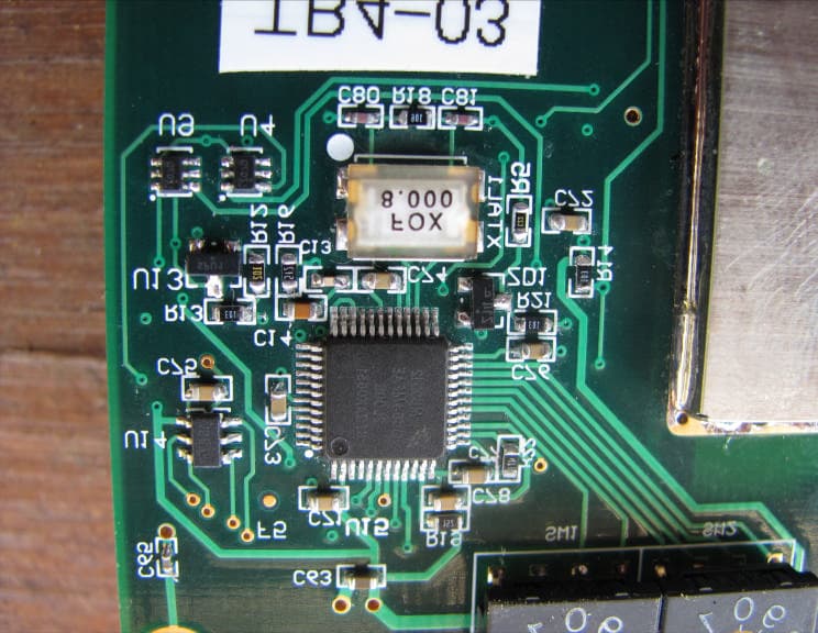
Click to zoom
Application Details
- Equipment Class
- DTS - Digital Transmission System
- Date of Grant
- Mar 26, 2010
- Application Purpose
- Original Equipment
- Date of Application
- Mar 26, 2010
- Equipment Note
- 2.4 GHz Transceiver Module
- Frequency Range
- 2468.00000000 - 2476.00000000
- Company
- Preston Cinema Systems Inc
- Country
- United States
Documents & Files
Document Text
Text extracted from the exhibit documents filed with the FCC. Open a document above to read the original.
Users Manual
F I + Z Lens Control Rev 3.0 Preston Cinema Systems 1659 Eleventh Street Santa Monica, CA 90404 2 Table of Contents I. Introduction A. System B. Hand Unit 3 C. Micro Force Zoom D. Remote Iris Box E. Optional Wireless Units F. MDR2 G. DM-1, DM-2 motors II. FI+Z Basic Operation Summary A. Motor Driver and Digital Motor set-up B. Hand Unit 3 III. Hand Unit Detailed Description A. Hand Grip 1. Configurations 2. Changing the hand grip B. HU3 Set-Up and Operation 1. Main Display 2. Menu Screen 3. Radio Channel Selection 4. Footage Counter 5. Camera Selection 6. Lens Set-Up 7. Operating Mode 8. System Menu 9. Lens Limits 10. Panatape and Cinetape interfaces. 11. Software Updates 12. Remote Iris Unit 13. Focus Ring Light/Dimming IV. MDR-2 Detailed Description V. Digital Motors VI. Camera and Lens Installation A. 15mm Arri B. 19mmArri C. Panavision D. Gears VII. Battery Packs and Charger VIII. Technical Information A. FCC Statement B. Connector Pin-Outs 1. Hand Unit 2. MDR2 C. MDR2 Camera Cable list D. Transmitter Channels and Frequencies E. 3D Reference 3 I. Introduction A. System. The classic FI+Z, wireless lens and camera control system is known worldwide for its combination of precision, simplicity and ruggedness. It consists of the Hand Unit, Motor Driver, a set of Digital Motors, a Micro Force zoom control, and a variety of optional controls including wireless Focus/Iris, Zoom, and F/X units. The FI+Z system controls the complete array of both lens and camera functions B. The Hand Unit 3 adds impressive new features and functionality to the system. It integrates its 30 channel 2.4GHz wireless link into a new splash-resistant housing. The built-in microwave antenna is protected from impact. The iris slider uses a unique non contact technology to eliminate the opening required for a conventional sliding seal. The Hand Unit digitizes focus, iris, and zoom commands to 16 bits of resolution (1 part in 65,536). This data is sent to the 3 Channel Motor Driver either through a cable or the Microwave Link. The cable link uses the RS422 standard protocol to transmit data over a single twisted pair of wires. This enables reliable transmission over long distances (1 km). New software called "Lens Mapping" matches the focus distance marks of a lens to a set of five pre-printed Focus Marking Rings. These rings differ in their minimum focus distance from 9" (.35m) to 6' (2m). Once a lens is calibrated, it can immediately be used with any of the focus rings. The on-board lens library holds data for 150 lenses. Calibration for a lens change only requires the few seconds needed to choose the lens from the library. A bright, sharp, organic LED display shows camera, lens, and Hand Unit set-up status. Focus distance settings can be displayed digitally for Cooke i-Lenses, or any lens which has been calibrated to the unit. Data from compatible ultrasonic or laser measuring devices (Panatape, Cinetape, Sniper ) can be displayed . A new focus display mode "Marks" gives an easy to interpret bargraph representation of the difference between the distance set by the focus knob and reference marks entered by the user. Multiple reference marks can be set by entering their position with a "soft key" located below the display. Ergonomics have been improved with the addition of an integrated hand grip and a molded grip for the focus knob. The focus marking ring is automatically illuminated in low light conditions by a pair of white LED's. The zoom bargraph shows both the zoom lens position as well as user set end limits. End limits are set with Set/ Reset tactile switches arranged in three groups. An LED in each group indicates when limits are active. The HU3 allows for programming camera speed and shutter angle. Despite all of its additional functionality, the weight of the new hand unit is about 20% less than its predecessor. Power is provided by widely available FM-50 Li-Ion batteries. C. The zoom function is implemented by a Micro Force control. It can be directly connected to the Hand Unit using a bracket or operated remotely using a cable. The camera may be started either from the Micro Force or from the Hand Unit. D. The Remote Iris Box provides a separate control for the Iris function. It is automatically enabled when plugged into the Iris accessory connector on the Hand Unit. E. Optional wireless units allow various lens and camera control functions to be split off from the Hand Unit functions. The Focus-Iris unit is a single channel hand control. When active, it takes over either the focus or iris function from the Hand Unit. The F/X unit adds camera speed ramps with iris and/or shutter compensation as well as recording and 4 playback functions. The Radio Micro Force module allows the zoom function to be split off from the Hand Unit. F. The Motor Driver (MDR2) supports 3 motor channels, camera run/stop, and camera speed and shutter control. It provides control over the speed and shutter angle over all of the major film cameras in use today that support external control. The 30 channel transceiver allows the simultaneous operation of both the Hand Unit 3 as well as the optional wireless hand units listed previously. An integral voltage booster allows for operation over a voltage range of 11 – 28 VDC. Switches are provided for adjusting Motor Torque and reversing direction. G. DM-1X and DM-2 digital motors provide the ultimate in power and reliability. They have proven their toughness under extremes of temperature, humidity and vibration. Their housings are machined from solid magnesium billets and protected by a special ceramic coating before painting. This provides exceptional resistance to salt spray and moisture. II. FI+Z Basic Operation Summary. A. Set-up the Motor driver (MDR2) and Digital Motors. a. Slide the motor brackets onto the matte box support rods. Position the motors and brackets so that the motor gears mesh with the corresponding lens gears. Couple the lens motors to the lens gears . Adjust the moto…
Text truncated - open the document above for the full version.
Users Manual
Focus-Iris Manual Ver 1.0 Preston Cinema Systems • 1659 Eleventh Street • Santa Monica CA 90404 tel 310-453-1852 fax 310-453-5672 www.prestoncinema.com Table of Contents 1. Description 2. Operation 3. Specifications 4. FCC Statement 1.0 Description The Focus-Iris unit is a single channel wireless control. It can be used to control either the focus or iris channel of an MDR2, wireless V+F Lens Control, or Radio Dimmer. The switch located near the top of the control selects between the focus and iris function. An FM50 type Li-Ion Battery (11) powers both the Radio module. To remove the battery, slide the Battery Release (12) towards the rear of the module while pushing the battery downwards. The omni-directional antenna element (1) is housed within a rugged cover that protects it against impact. The tri-color LED (4) indicates the strength of the received signals: Blue – Maximum Green – Strong Red – Minimum (off) – Signal Strength too low. Move closer to MDR2 for reliable operation. There are 30 wireless channels available numbered from 0 – 29. These correspond to the channels on the MDR2, V+F Lens Control and Radio Dimmer. The channel is raised or lowered by pressing the pair of buttons (7) to the right of the channel indicator (6). 1 2 3 4 5 6 7 8 9 10 Front View Rear View 11 12 13 14 15 1. Antenna 2. Focus/Iris mode switch 3. Camera R/S 4. Link LED shows signal strength 5. Power Switch 6. Wireless Channel indicator 7. Channel Switches 8. Lens position indicator 9. Set/Reset limit switches 10. Lens position bargraph 11. Li-Ion Battery 12. Battery Release 13. Neck-strap attachment 14. Marking Ring 15. Control Knob 2.0 Operation 1. Install a charged Li-Ion battery 2. Set up the Motor Driver or Radio Dimmer. Apply power. Note the channel setting. If the device being controlled is a Video Lens Control or Radio Dimmer, set the mode to either Focus or Iris, so that it can be controlled by the Focus-Iris unit. 3. Press the POWER button (5) momentarily. The power LED just above the switch will light. 4. Use the push-button switches (7) to match the channel as shown in the display (6) to the channel of the receiving unit. 5. Select the desired mode – focus or iris: • If an MDR2 is being controlled, the Mode switch determines which motor ( focus or iris) will respond to the control knob. • If a Video Lens control is being used, the Mode setting of both units must match (focus or iris). 6. When the Focus-Iris unit establishes communication with the Motor Driver or Dimmer, the LINK LED (4) will glow. The color will indicate the signal strength as described in the previous section. 7. The Control Knob (15) will now control either the motor or LED light. 8. The Camera Run LED located above the R/S Switch (3) indicates the camera status. 9. To set Lens Limits: a. Use the Control Knob to move the lens to one end of the desired range. b. While pressing the SET BUTTON (9), turn the Control Knob until the lens reaches the other end of the desired range. c. Release the SET BUTTON. d. The end limits of lens rotation are indicated by the solid glowing bars. The moving bar shows the current lens position. e. The limits can be removed by pressing the RESET button momentarily. 3.0 Specifications: Size: 100mm x 77mm x 28mm (4” x 3” x 1.2” ) Weight: 340g (12 oz) Typical operating time: 6 hours Battery Type: 7.4V 1.5AH (FM50 enhanced type) Charger: Sony BC-VM50 with US standard line plug. Charger Operating voltage 100 – 240 VAC. Charge Time: 4.5 hours 5. FCC Statement This equipment has been tested and found to comply with the limits for a class B digital device, pursuant to part 15 of the FCC Rules. These limits are designed to provide reasonable protection against harmful interference in a residential installation. This equipment generates, uses and can radiate radio frequency energy and if not installed and used in accordance with the instructions, may cause harmful interference to radio communications. However, there is no guarantee that interference will not occur in a particular installation. If this equipment does cause harmful interference to radio or television reception, which can be determined by turning the equipment off and on, the user is encouraged to try to correct the interference by one or more of the following measures: * Reorient or relocate the receiving antenna. * Increase the separation between the equipment and receiver. * Connect the equipment into an outlet on a circuit different from that to which the receiver is connected. * Consult the dealer or an experienced radio/TV technician for help. This equipment has been verified to comply with the limits for a class B computing device, pursuant to FCC Rules. Operation with non-approved equipment is likely to result in interference to radio and TV reception. The user is cautioned that changes and modifications made to the equipment without the approval of manufacturer could void the user's authority to operate this equipment. This device complies with Part 15 of the FCC Rules. Operation is subject to the following two conditions: (1) This device may not cause harmful interference and (2) This device must accept any interference received including interference that may cause undesired operation. FCC RF EXPOSURE STATEMENT To satisfy RF exposure requirements, this device and its antenna must operate with a separation distance of at least 20 cm from all persons and must not be co-located or operating in conjunction with any other antenna or transmitter.
Users Manual
Radio Micro Force Manual v1.0 Preston Cinema Systems • 1659 Eleventh Street • Santa Monica CA 90404 tel 310-453-1852 fax 310-453-5672 www.prestoncinema.com Table of Contents 1. Description 2. Operation 3. Specifications 4. FCC Statement 1.0 Description The Radio Micro Force Module adds wireless operation to either the analog Micro Force V+F2 or Digital Micro Force controls. It can be used to control the zoom channel of an MDR2, wireless V+F Lens Control, or Radio Dimmer. The module is attached to the Micro Force control with an articulating bracket and attachment knob (15). The adjustment knob ( 9 ) allows the user to change the viewing angle. A short cable (16) connects the Micro Force control to the Radio Micro Force module. A Li-Ion Battery (14) powers both the Radio module as well as the Micro Force control. To remove the battery, press the Battery Release (7) towards the rear of the module while pushing the battery downwards. The omni-directional antenna element (1) is housed within a rugged cover that protects it against impact. The tri-color LED indicates the strength of the received signals: Blue – Maximum Green – Strong Red – Minimum (off) – Signal Strength too low. Move closer to MDR2 for reliable operation. There are 30 wireless channels available numbered from 0 – 29. These correspond to the channels on the MDR2, V+F Lens Control and Radio Dimmer. The channel is raised or lowered by pressing the pair of buttons (10) to the right of the channel indicator (6). 2.0 Operation 1. Install a charged Li-Ion battery 2. Set the channel to match that of the MDR2 or other compatible receiving device. Set up the MDR2 with motors. Apply power. 3. Press the POWER button (5) momentarily. The power LED (4) will light. 4. When the RMF establishes communication with the MDR2, the LINK LED (2) will glow. The color will indicate the signal strength as described in the previous section. 5. The Micro Force joystick (8) will now control the zoom motor. The Camera Run LED (3) indicates the camera status. 6. To set Lens Limits: a. Use the joystick to move the zoom one end of the desired zoom range. b. While pressing the SET BUTTON, move the zoom to the other end of the range. c. Release the SET BUTTON. d. The end limits of lens rotation are indicated by the solid glowing bars (11). The moving bar shows the current lens position. e. The limits can be removed by pressing the RESET button momentarily. 1 2 3 4 5 6 11 10 9 8 7 12 13 14 15 16 17 7. Slide switch (17) selects the operating mode. a. Normal mode is for driving digital motors. The bargraph displays the lens position and any limits the user has set. b. Video mode is for driving the internal motor of video lenses. The bargraph indicates the information sent to the lens: the length of the illuminated bars is proportional to the zoom velocit y (not position as for “Normal” mode). A “video” cable must be used to connect the video lens to the MDR2 or V+F Lens control. 8. The LED above the POWER switch glows solid red to indicate normal operation. The LED will flash when less than 15% of the battery charge remains. Install a charged battery at this time. 9. Zoom Drift. The Micro Force may need occasional adjustment to eliminate zoom drift (the zoom motor moves slowly without any pressure on the joystick). This drift can be cancelled by simultaneously pressing both the SET and RESET buttons. 10. The Radio Micro Force can be reset to its default state by: a. Power down the unit. b. Hold down the RESET button and press the POWER button. Release both buttons. This will erase any memorized limits or offsets. 3.0 Specifications: Size: 100mm x 77mm x 28mm (4” x 3” x 1.2” ) Weight: RMF module: 340g (12 oz) Bracket: 130g (4.5 oz) Typical operating time: 8 hours Battery Type: 7.4V 1.8AH (FM50 enhanced type) Charger: Sony BC-VM50 with US standard line plug. Charger Operating voltage 100 – 240 VAC. Charge Time: 4.5 hours Product Numbers: 4015 RMF with cable for Digital Micro Force 4016 RMF with cable for Micro Force V+F2 4017 RMF cable (spare) for Digital Micro Force 4018 RMF cable (spare) for Micro Force V+F2 4915 FM50 Li-Ion Battery (spare) 4916 Charger for FM50 battery w/ US standard line cord 14 16 15 4 FCC Statement This equipment has been tested and found to comply with the limits for a class B digital device, pursuant to part 15 of the FCC Rules. These limits are designed to provide reasonable protection against harmful interference in a residential installation. This equipment generates, uses and can radiate radio frequency energy and if not installed and used in accordance with the instructions, may cause harmful interference to radio communications. However, there is no guarantee that interference will not occur in a particular installation. If this equipment does cause harmful interference to radio or television reception, which can be determined by turning the equipment off and on, the user is encouraged to try to correct the interference by one or more of the following measures: * Reorient or relocate the receiving antenna. * Increase the separation between the equipment and receiver. * Connect the equipment into an outlet on a circuit different from that to which the receiver is connected. * Consult the dealer or an experienced radio/TV technician for help. This equipment has been verified to comply with the limits for a class B computing device, pursuant to FCC Rules. Operation with non-approved equipment is likely to result in interference to radio and TV reception. The user is cautioned that changes and modifications made to the equipment without the approval of manufacturer could void the user's authority to operate this equipment. This device complies with Part 15 of the FCC Rules. Operation is subject to the following two conditions: (1) This device may not cause harmful interference and (2) This device must accept any interference received including interference that may cause undesired operation. FCC RF EXPOSURE STATEMENT To satisfy RF exposu…
Text truncated - open the document above for the full version.
Users Manual
V+F Lens Control Manual v1.0 Preston Cinema Systems 1659 Eleventh Street Santa Monica, CA 90404 tel 310-453-1853 fax 310-453-5672 www.prestoncinema.com Table of Contents 1. Description 2. Operation 3. Specifications 4. Cables 5. FCC Statement 1. Description. The V+F Lens Control is available as a single channel wireless/cable control (p/n 4050) or a cable only version (p/n 4051). Both are used with DM-1 or DM-2 digital motors. The cable only version is intended to control the iris function of cinema style lenses mounted on video cameras. In this mode, the iris is controlled through: • the cameras’ remote set-up box (Sony RMB-150 or equivalent) • through the cable connected Remote iris Box (p/n 4020) • through the on-board control knob. The wireless version adds the possibility of control through any of three wireless hand units: • Focus-Iris Hand Unit (p/n 4024) • FI+Z Hand Unit w/ MW Transmitter (p/n 4000 + 4910) • Radio Micro Force unit (p/n 4015 or 4016) Wireless channels are indicated on the digital display. A three position switch adjusts the motor torque level, and a second switch determines the direction of motor rotation. The small size of the control makes it especially suitable for hand held use. The FI+Z Hand Unit (p/n 4000 with Microwave Transmitter p/n 4910), the Focus-Iris Hand Unit (p/n 4024) or the Radio Micro Force (p/n 4015 or 4016) can all be used for wireless operation with version p/n 4050. The mode switch selects whether the unit responds to Focus, Iris, or Zoom commands. Camera Run/VTR signals are available for controlling all film and video cameras. The unit operates over a voltage range of 11 - 30 VDC. For video cameras, all power and control signals are provided through the 12-pin Hirose on the camera. Film cameras having accessory receptacles capable of 1.5A @ 24V (Arri 435, Panavision) can also be used to provide both power and camera run functions. Otherwise separate receptacles are provided for external power and Camera Run/VTR. 2. Operation . A. Camera Connections and Mounting a. Secure the V+F Lens Control to the Matte Box Support Rods using the Mounting Bracket. The jaw opening is adjusted to accommodate different rod sizes by turning the free half of the bracket as shown in the picture above. b. The V+F unit can be powered directly from the camera, or through a separate power cable. The cables for connection to the camera are p/n 4620 ~ 4630, and the power cables are p/n 4640, and 4641. See the complete list of cables in Section 4 of this document. c. Connect the digital motor (DM-1 or DM-2) with the motor cable (p/n 4410 ~ 4412). d. Use a Swing Arm Motor Bracket (p/n 4301 ~ 4303, 4333) to attach the motor to the Matte Box Support Rods. Engage the motor to the lens. p/n 4050 Wireless Version p/n 4051 Cable Only Version VLC Receptacles Mounting Bracket p/n 4342 B. Set-up Procedure-Video Camera Calibration i. Power the camera. ii. Wireless Version only: Set the mode to Video by pressing the mode button until the “Video Iris” LED is lit. Press the “Cal” button. The Digital Motor will find the end stops of the lens. The f2.8 LED should be blinking. Using the knob on the VLC to move the iris to f2.8 and press the “Cal” button again. Now the F16 LED will blink. iii. Cable Only Version. There is no mode switch on this unit. Initiate calibration by pressing the “Cal” button. After the motor finds the end stops of the lens, the F2.8 LED will blink. Use the knob to set the lens to F2.8 and press the “Cal” button again. Now the F16 LED will blink. Adjust the lens to F16 and press the “Cal” button. Turn the knob until the iris is at F16 and press the Cal button. The lens is now calibrated to the video camera and the engraved F-stop marks on the knob should match those of the lens. C. Set-Up Procedure for wireless operation. The V+F (p/n 4050) can be controlled through its microwave link by the following hand controls: a. The FI+Z Hand Unit b. The Focus-Iris Hand Unit c. The Radio Micro Force module with a Micro Force control. Communication between the Hand Unit and the V+F will be established when both units are set to the same channel. The wireless channel is by using the channel button located to the right of the LED channel display. D. Control of the motor can be switched from an external source (wireless Hand Unit or RMB150 type device) to the knob by pressing the “Local” button. The red LED will be lit when the unit is under local control. E. The V+F may also be controlled via a cable connection through the Remote Iris Box (p/n 4020). To use this device with the V+F, place the unit into the “Local” mode and connect the Iris Box to the V+F “Remote” receptacle with cable 4642 VLC and Digital Motor with brackets 3. Specifications Size 107mm x 66mm x 45mm (4.2" x 2.6" x 1.75") Weight: 350g Power Requirements: 11 - 30 VDC 0.2A quiescent at 12VDC. 4. Cables and Accessories 4342 Mounting Bracket (spare) for 15 – 19mm rods 4620 Camera Cable Arriflex 12V 11-pin Fischer 4621 Camera Cable Arriflex 24V 3-pin Fischer 4622 Camera Cable Panavision Film 4623 Camera Cable Panavision Genesis 4624 Camera Cable Aaton 4630 Camera Cable Sony 4640 Aux Power Cable 12V 4-pin XLR 4641 Aux Power Cable 24V 3-pin XLR 4642 Remote Iris Cable Box 8’ 5. FCC Statement Remote Iris Box p/n 4020 This equipment has been tested and found to comply with the limits for a class B digital device, pursuant to part 15 of the FCC Rules. These limits are designed to provide reasonable protection against harmful interference in a residential installation. This equipment generates, uses and can radiate radio frequency energy and if not installed and used in accordance with the instructions, may cause harmful interference to radio communications. However, there is no guarantee that interference will not occur in a particular installation. If this equipment does cause harmful interference to radio or television reception, which can be determined by turning the equipment off and on, the user is encouraged to try…
Text truncated - open the document above for the full version.
Attestation Statements
February 3, 2010 Dear Application Engineer: The product to be approved under FCC ID: NMRTR41 for FCC authorization is to be for a modular approval. The requirements of FCC 15.212 are met. The following requirements are fulfilled: 1. The modular transmitter must have its own RF shielding. The module contains a metal shield over the transmitter section to ensure that it does not have to rely upon shielding provided by the device into which it is installed and to prevent coupling into which the device will be installed. 2. The modular transmitter must have buffered modulation/data inputs. Data to the modulation circuit passes through buffers and a microprocessor before being applied to the RF modem IC. Refer to “Theory of Operation”, TR41 Transceiver Block Diagram. 3. The modular transmitter must have its own power supply regulation All of the circuitry is powered by 3.3V regulator. The range of allowable input voltage is 4.0 – 10VDC, 5.0V nominal. 4. The modular transmitter must comply with the antenna requirements of Section 15.203 and 15.204c The module is configured either with a reverse-polarized SMA connector or a Hirose U.FL receptacle. These types of connectors comply with the requirements of sections 15.203 and 15.204(c). 5. The modular transmitter must be tested in a stand-alone configuration The EUT was tested with the support equipment being at least 10 centimeters away, which meets the minimum separation distance required for the EUT per 15.212 (1)(v). 6. The modular transmitter must be labeled with its own FCC ID number The module will be labeled with its own FCC ID number. When the EUT is installed inside one of our end products the label will not be visible. The end product will then contain the following label below permanently attached in a conspicuous location: 6. The modular transmitter must comply with any specific rule or operating requirements applicable to the transmitter and the manufacturer must provide adequate instructions along with the module to explain any such requirements. The EUT is compliant with all applicable FCC rules. Detailed instructions are given in the Users Guide. Please note that this RF module will only be used for in-house production only and not provided to any outside parties for other use. 7. The modular transmitter must comply with any applicable RF exposure requirements. The EUT meets the RF exposure requirements because the EUT is a mobile unit (will be at least 20 centimeters away from the user) and the MPE is 0.0667249384 mW/cm 2 at 20 centimeters which is below the limit of 1 mW/cm 2 allowed for the general population. Please contact me at 310-453-1852 if you have any additional questions. Best Regards, Howard Preston President Preston Cinema Systems Contains Transmitter Module FCC ID: NMRTR41
Attestation Statements
1 PrestonCinemaSystems 1659 Eleventh Street Santa Monica, CA 90404 t 310-453-1852 f 310-453-5672 February 1, 2010 Compatible Electronics TCB 114 Olinda Drive Brea, California 92823 Gentlemen: This is a letter of authorization to accept that any personnel of Compatible Electronics, Inc. as an Agent for Preston Cinema Systems,1659 Eleventh Street, Santa Monica, CA 90404, for a period of one year, to sign applications before the certification body on our behalf, to make representations to you on our behalf, and to receive and exchange data between our company and the certification body in connection with certification of the following Preston Cinema Systems products: TR41 Module under FCC Docket Number 20780 and General Docket Number 80-284 pursuant to Part 15 of the FCC Rules and Regulations. Please also accept this letter as an attestation that neither Preston Cinema Systemsnor any of its officers, directors, or persons holding 5% or more of the outstanding stock or shares, voting or non-voting, have been denied federal benefits under section 5301 of the Anti-Drug Abuse act of 1988, 21 U.S.C. 853(a). In addition, Preston Cinema Systemswill notify the Federal Communications Commission if, at any time, the situation changes causing Preston Cinema Systemsto be denied federal benefits. If you have any further questions or need additional information, please feel free to give me a call at 310-453-1852. Sincerely, Howard Preston President Preston Cinema Systems Howard Preston Digitally signed by Howard Preston DN: cn=Howard Preston, o=Preston Cinema Systems, ou=President, [email protected], c=US Date: 2010.02.01 17:08:59 -08'00'
Attestation Statements
2 PrestonCinemaSystems 1659 Eleventh Street Santa Monica, CA 90404 t 310-453-1852 f 310-453-5672 February 1, 2010 Compatible Electronics TCB 114 Olinda Drive Brea, California 92823 Subject: TCB application submittal Gentlemen: We, Preston Cinema Systems would like to declare that the application being submitted for the device with FCC ID: NMRTR41,has not beensubmitted to another TCB for certification. The application was submitted to Compatible Electronics TCB on February 1, 2010 If you have any questions, please do not hesitate to contact us at 310-453-1852 Sincerely, Howard Preston President Preston Cinema Systems Howard Preston Digitally signed by Howard Preston DN: cn=Howard Preston, o=Preston Cinema Systems, ou=President, [email protected], c=US Date: 2010.02.01 17:09:26 -08'00'
Cover Letter(s)
3 PrestonCinemaSystems 1659 Eleventh Street Santa Monica, CA 90404 t 310-453-1852 f 310-453-5672 February 1, 2010 Compatible Electronics TCB 114 Olinda Drive Brea, California 92823 Subject: Request for withholding from public disclosure the schematic diagrams, block diagrams, and operational description pursuant to an application for certification. Gentlemen: We Preston Cinema Systems would like to request that all schematics, block diagrams, and operational descriptions submitted with our application for certification be withheld from public disclosure per Section 0.459 of the FCC rules. This request is made under the provisions of Section 0.457 (d) of the Commissions rules, and Section 552 (b)(4) of the Freedom of Information Act. These sections authorize the withholding from public inspection, those materials which would be privileged as a matter of law if retained by the person submitting them, and materials which would not customarily be released to the public by that person. If you have any questions or need any additional information, please give me a call at 310-453-1852 Sincerely, Howard Preston President Preston Cinema Systems Howard Preston Digitally signed by Howard Preston DN: cn=Howard Preston, o=Preston Cinema Systems, ou=…
Text truncated - open the document above for the full version.
Contact Information
Applicant
Howard Preston(Owner)
Technical Contact
Compatible Electronics, Inc.Kyle Fujimoto
[email protected]714-579-0500
114 Olinda Drive · Brea, California · United States
Test Firm
Compatible Electronics, Inc.Michael Christensen
Technical Specifications
| # | Rule Parts | Frequency Range | Power Output |
|---|---|---|---|
| 3 | 15C | 2.47 GHz - 2.48 GHz | 15.14 mW |
Other Applications from Preston Cinema Systems Inc
NMRTR6
Aug 11, 20242.4 GHz Transceiver
Equipment Class
DTS - Digital Transmission SystemNMRFIZTX240
Nov 20, 1997Camera Control Transmitter Maximum output power: 100 mW
Equipment Class
DSS - Part 15 Spread Spectrum Transmitter