NN7MT2000TAutomotive Remote Control
DK Technologies Inc.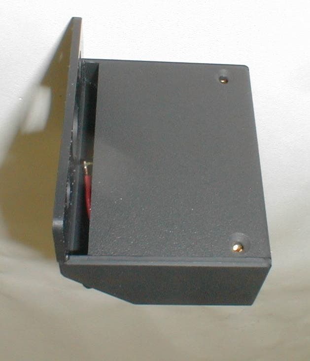
Click to zoom
Application Details
- Equipment Class
- DSC - Part 15 Security/Remote Control Transmitter
- Date of Grant
- May 24, 2002
- Application Purpose
- Original Equipment
- Date of Application
- May 24, 2002
- Equipment Note
- Automotive Remote Control
- Frequency Range
- 433.88000000 - 433.88000000
- Company
- DK Technologies Inc.
- Country
- United States
Documents & Files
Document Text
Text extracted from the exhibit documents filed with the FCC. Open a document above to read the original.
Users Manual
MiniTouch Control System User Instructions DK Technologies, Inc. 9 Regola Drive Irwin, PA 15642 (724) 744-0420 Introduction The Mini Touch Hand Control System is designed to allow activation of up to 12 vehicle functions traditionally found on the left side of the steering column. These include (but are not limited to) turn signals, windshield wiper and washer, and high beam controls. The system is designed to operate in parallel with the original factory installed controls. System Components The MiniTouch system consists of an radio transmitter that is mounted to a spinner knob on the steering wheel, and a RF receiver module mounted underneath the dash. Each component will be described below. Note: The system is active only when the ignition switch is in the ON position. Transmitter The transmitter is the user’s interface to the system. It consists of up to 6 dual position momentary toggle switches. The transmitter is powered a 3.6 V battery located in the compartment on the rear of the transmitter. The battery should last for a minimum of 1 year of normal use. Note: As a function is activated, the LED on the top of the transmitter will flash. If it does not flash or if the response of the system becomes erratic, replace the battery. To replace the battery, remove the back cover of the transmitter. Place a new 3.6 V lithium battery (type 2/3 A) in the holder. Be sure to place the “+” terminal of the battery to the the “+” terminal of the battery holder. AGENCY NOTICE Changes or modifications not expressly approved by the manufacturer could void the user's authority to operate the equipment. RF Receiver Module The RF receiver module is the direct interface to the vehicle’s electronics. The receiver translates the data sent by the transmitter into signals to control vehicle functions. The signals control external relays. It is mounted underneath the dash and is connected into the existing vehicle wiring.
Block Diagram
6 SPST Switches HCS300 Rolling Code Encoder Switch Board TXM-433-LC Transmitter Module ANT-433-SP Antenna +VGND DATA 3.6 V Battery +VGND MT1 Remote Control Transmitter Block Diagram
Cover Letter(s)
DK Technologies, Inc. 9 Regola Drive Irwin PA 15642 724-744-0420 Request for Confidentiality Date: 3-19-01 American Telecommunications Certification Body, Inc. 6731 Whittier Avenue Suite C110 McLean, VA 22101 RE: Certification Application FCC ID: NN7MT2000T Please be advised that the following information for FCC ID: NN7MT2000T is to be held confidential on behalf of DK Technologies, Inc: • Schematics • Theory of Operation The above named exhibits contain technical information which DK Technologies, Inc. deems to be trade secrets and proprietary. If made public, the information might be used to the disadvantage of the applicant in the market place. Thank you for your attention to this matter. Daniel J. Janicik President DK Technologies, Inc.
Cover Letter(s)
American Telecommunications Certification Body Inc. 6731 Whittier Ave, McLean, VA 22101 May 23, 2002 RE: FCC ID: NN7MT2000T Attention: Brian Dettling I have a few comments on this Application. 1 The confidentiality letter has the wrong FCC ID number for this application. Please provide a revised Confidentiality Letter with the correct FCC ID number. 2 The Operational description of the devices states that the antenna is a “circuit board trace that is located around the edge of the board. It is approximately 4.277" long by 0.025" wide and is matched with an inductor and capacitor to provide maximum allowed power output.” However, the Internal Photos show no such trace, but does show a 433-SP2 Linx grounded line planar antenna. Please explain and/or correct the technical description. 3 In the report (page 10 sec 4.4) you state that for the occupied BW the output of the EUT was coupled to the input of the analyzer. Was this coupling done using a near field probe, direct connection or was it done at 3 meters using an antenna? The reason I ask is that the level is close to the calculated field strength levels only slightly higher. This may be coincidence, but a short explanation of the coupling mechanism will help clarify the similarities in levels. This does not affect the data, it is only for information purposes. Dennis Ward mailto:[email protected] The items indicated above must be submitted before processing can continue on the above referenced application. Failure to provide the requested information may result in application termination. Correspondence should be considered part of the permanent submission and may be viewed from the Internet after a Grant of Equipment Authorization is issued. Please do not respond to this correspondence using the email reply button. In order for your response to be processed expeditiously, you must submit your documents through the AmericanTCB.com website. Also, please note that partial responses increase processing time and should not be submitted. Any questions about the content of this correspondence should be directed to the sender.
Cover Letter(s)
Response to ATCB Comments on application for FCC ID: NN7MT2000T, prepared by Washington Laboratories, Ltd. May 24, 2002. Responses are in BOLD ITALIC. May 23, 2002 RE: FCC ID: NN7MT2000T Attention: Brian Dettling I have a few comments on this Application. 1 The confidentiality letter has the wrong FCC ID number for this application. Please provide a revised Confidentiality Letter with the correct FCC ID number. Please see exhibit “Corrected MT1 RFC Letter.pdf” 2 The Operational description of the devices states that the antenna is a “circuit board trace that is located around the edge of the board. It is approximately 4.277" long by 0.025" wide and is matched with an inductor and capacitor to provide maximum allowed power output.” However, the Internal Photos show no such trace, but does show a 433-SP2 Linx grounded line planar antenna. Please explain and/or correct the technical description. Please see exhibit “Revised MT1 Operational Description.pdf”. Additionally, a block diagram that more accurately reflects the product has been provided. Please see “Revised MT1 Block Diagram.pdf” 3 In the report (page 10 sec 4.4) you state that for the occupied BW the output of the EUT was coupled to the input of the analyzer. Was this coupling done using a near field probe, direct connection or was it done at 3 meters using an antenna? The reason I ask is that the level is close to the calculated field strength levels only slightly higher. This may be coincidence, but a short explanation of the coupling mechanism will help clarify the similarities in levels. This does not affect the data, it is only for information purposes. Per Greg Snyder, WLL Chief EMC Engineer: The antenna was randomly placed at a distance closer than three meters to the test item. The actual distance was not documented, as the test was set up to record a bandwidth plot. Dennis Ward mailto:[email protected] The items indicated above must be submitted before processing can continue on the above referenced application. Failure to provide the requested information may result in application termination. Correspondence should be considered part of the permanent submission and may be viewed from the Internet after a Grant of Equipment Authorization is issued. Please do not respond to this correspondence using the email reply button. In order for your response to be processed expeditiously, you must submit your documents through the AmericanTCB.com website. Also, please note that partial responses increase processing time and should not be submitted. Any questions about the content of this correspondence should be directed to the sender.
External Photos
External Views
ID Label/Location Info
Model: MT1 S/N: FCC ID: NN7MT2000T This device complies with Part 15 of the FCC rules. Operation is subject to the following two conditions: (1) This device may not cause harmful interference, and (2) this device must accept interference received, including interference that may cause undesired operation. 2" 1"
Internal Photos
Internal Views
Operational Description
DS000059 Ver 1.1 MAR 00 ©1999 Reg. No. 227 4001, ENGLANDPage 1 FM SIL TRANSMITTER MODULE FM-RFT3-XXX • COMPLETE FM TRANSMITTER • TRANSMIT RANGE UP TO 250m • CMOS/TTL INPUT • SIL PACKAGE • NO ADJUSTABLE COMPONENTS • VERY STABLE OPERATING FREQUENCY • LOW CURRENT CONSUMPTION (TYP 8mA) • WIDE OPERATING VOLTAGE (2.7-14V) • AVAILABLE AS 315, 418 OR 433 MHz • COMPATIBLE WITH RF SOLUTIONS FM RECEIVERS Applications • WIRELESS SECURITY SYSTEMS • CAR ALARMS • REMOTE GATE CONTROLS • REMOTE SENSING • DATA CAPTURE • SENSOR REPORTING Description The R F Solutions Ltd. FM hybrid transmitter module provides a complete RF transmitter which can be used to transmit data at up to 9.6 KHz from any standard CMOS/TTL source. The module is very simple to operate and offers low current consumption (typ. 8 mA). Data can be supplied directly from a microprocessor or encoding device, thus keeping the component count down and ensuring a low hardware cost. The module exhibits extremely stable electronic characteristics due to the use of ‘Thick-Film’ hybrid technology, which uses no adjustable components and ensures very reliable operation. The modules are compatible with R F solutions Ltd. range of FM receivers to provide a complete solution. Circuit Schematic External Antenna Data In V CC DS000059 Ver 1.1 MAR 00 ©1999 Reg. No. 227 4001, ENGLANDPage 2 FM SIL TRANSMITTER MODULE FM-RFT3-XXX Mechanical Dimensions Pin Description Pin NumberNameDescription 1EAExternal Antenna 2INData input 6GNDGround, Connect to RF earth return path 7VccSupply Voltage Typical Application Antenna Configuration 1267 Component Side 22.86mm 11.43mm 2.54mm A0 A1 A2 A3 A4 A5 A6 A7 VSSAD8 AD9 AD10 AD11 TE\ OSC2 OSC1 DOUT VDD 1 2 3 4 5 6 7 8 910 11 12 13 14 15 16 17 18 HT12E R OSC +5V ANTENNA RFT3-XXX +5V 1267 RF 17.3cm @ 433MHz RF GND RF Loop Antenna Area 4 To 10cm 2 Track Width 1mm Capacitor 1.5 - 5pF Fixed or Variable RF 34 Turns of enamelled copper wire diameter 0.5mm close wound on 2.5mm diameter former Helical Coil AntennaLoop AntennaWhip Antenna DS000059 Ver 1.1 MAR 00 ©1999 Reg. No. 227 4001, ENGLANDPage 3 FM SIL TRANSMITTER MODULE FM-RFT3-XXX Technical Specifications ELECTRICAL CHARACTERISTICSMINTYPICALMAXDIMENSION Supply Voltage2.714VDC Supply Current (Vcc = 5V, IN=1KHz Square Wave)8mA Frequency Deviation50KHz RF Output into 50Ω (Vcc=5V) 7dBm Harmonic Spurious Emissions-50dBc Input High Voltage2.5VccV Max Data Rate9.6KHz Operating Temperature-25+80 °C Part Numbering Part NumberDescription FM-RFT3-315SIL FM Transmitter Module 315 MHz FM-RFT3-433SIL FM Transmitter Module 433 MHz For more information or general enquiries, please contact our official UK distributor; RF Solutions Ltd., Unit 21, Cliffe Industrial Estate, South Street, Lewes, E Sussex, BN8 6JL. England Tel +44 (0)1273 898 000 Fax +44 (0)1273 480 661 Email [email protected]://www.rfsolutions.co.uk RF Solutions is a member of the Low Power Radio Association All Trademarks acknowledged and remain the property of the respected owners Information contained in this document is believed to be accurate, however no representation or warranty is given and R.F. Solutions Ltd. assumes no liability with respect to the accuracy of such information. Use of R.F.Solutions as critical components in life support systems is not authorised except with express written approval from R.F.Solutions Ltd.
Test Report
Document 6406-01, Rev. 0 FCC ID: NN7NT2000T FCC Certification Test Report Washington Laboratories, Ltd May 2002 FCC Certification Test Report for DK Technologies, Inc. NN7NT2000T May 22, 2002 Prepared for: DK Technologies, Inc. 9 Regola Drive Irwin, PA 15642 Prepared By: Washington Laboratories, Ltd. 7560 Lindbergh Drive Gaithersburg, Maryland 20879 FCC Certification Test Report Document 6406-01, Rev. 0 FCC ID: NN7NT2000T FCC Certification Test Report Washington Laboratories, Ltd May 2002 FCC Certification Test Program FCC Certification Test Report for the DK Technologies, Inc. MT1 Transmitter NN7NT2000T May 22, 2002 WLL JOB# 6406 Prepared by: Brian J. Dettling Documentation Specialist Reviewed by: Gregory M. Snyder Chief EMC Engineer Document 6406-01, Rev. 0 FCC ID: NN7NT2000T FCC Certification Test Report Washington Laboratories, Ltd May 2002 ii Abstract This report has been prepared on behalf of DK Technologies, Inc. to support the attached Application for Equipment Authorization. The test report and application are submitted for a Periodic Intentional Radiator under Part 15.231 of the FCC Rules and Regulations. This Federal Communication Commission (FCC) Certification Test Report documents the test configuration and test results for a DK Technologies, Inc. MT1 Transmitter. Testing was performed on an Open Area Test Site (OATS) of Washington Laboratories, Ltd, 7560 Lindbergh Drive, Gaithersburg, MD 20879. Site description and site attenuation data have been placed on file with the FCC's Sampling and Measurements Branch at the FCC laboratory in Columbia, MD. Washington Laboratories, Ltd. has been accepted by the FCC and approved by NIST NVLAP (NVLAP Lab Code: 200066-0) as an independent FCC test laboratory. The DK Technologies, Inc. MT1 Transmitter complies with the limits for a Periodic Intentional Radiator device under Part 15.231 of the FCC Rules and Regulations. Document 6406-01, Rev. 0 FCC ID: NN7NT2000T FCC Certification Test Report Washington Laboratories, Ltd May 2002 iii Table of Contents Abstract......................................................................................................ii 1 Introduction...................................................................................................................1 1.1 Compliance Statement............................................................................................1 1.2 Test Scope............................................................................................................1 1.3 Contract Information..............................................................................................1 1.4 Test Dates.............................................................................................................1 1.5 Test and Support Personnel....................................................................................1 1.6 Abbreviations.........................................................................................................2 2 Equipment Under Test....................................................................................................3 2.1 EUT Identification & Description............................................................................3 2.2 Test Configuration..................................................................................................3 2.3 Testing Algorithm...................................................................................................3 2.4 Test Location.........................................................................................................3 2.5 Measurements........................................................................................................4 2.5.1 References.........................................................................................................4 2.6 Measurement Uncertainty.......................................................................................4 3 Test Equipment..............................................................................................................5 4 Test Results...................................................................................................................5 4.1 Duty Cycle Correction...........................................................................................5 4.2 RF Power Output: (FCC Part §2.1046)...............................................................10 4.3 Modulation Characteristics: (FCC Part §2.1047); Audio Frequency Response......10 4.4 Occupied Bandwidth: (FCC Part §2.1049)..........................................................10 4.5 Spurious Emissions at Antenna Terminals (FCC Part §2.1051...............................12 4.6 Radiated Spurious Emissions: (FCC Part §2.1053)...............................................12 4.6.1 Test Procedure..............................................................................................12 4.7 Frequency Stability: (FCC Part §2.1055).............................................................15 4.8 Transient Frequency Response (Part 90.214).........Error! Bookmark not defined. 5 Transmitter Environmental Assessment, Maximum Permissible Exposure (MPE)Error! Bookmark not defined. 5.1 SCOPE.................................................................Error! Bookmark not defined. 5.2 REFERENCE........................................................Error! Bookmark not defined. Document 6406-01, Rev. 0 FCC ID: NN7NT2000T FCC Certification Test Report Washington Laboratories, Ltd May 2002 iv List of Tables Table 1. Device Summary....................................................................................................3 Table 2: Test Equipment List................................................................................................5 Table 3. Duty Cycle Correction..........................................................................................10 Table 4. Radiated Spurious Emissions Limits..…
Text truncated - open the document above for the full version.
Test Setup Photos
Radiated Emissions Test Setup - X, Y, and Z Axis
Contact Information
Applicant
Daniel J Janicik(President)
Technical Contact
Washington Laboratories, Ltd.Gregory M Snyder
[email protected]301/ 417-0220
7560 Lindbergh Drive · Gaithersburg, Maryland · United States
Non-Technical Contact
Washington Laboratories, Ltd.Brian J Dettling
[email protected]301/ 417-0220
Test Firm
Washington Laboratories, Ltd.Michael Violette
Technical Specifications
| # | Rule Parts | Frequency Range | Power Output |
|---|---|---|---|
| 1 | 15.231 | 433.88 MHz - 433.88 MHz | - |
Other Applications from DK Technologies Inc.
NN7DK1000R
May 21, 1998CYY - Communications Receiver used w/Pt 15 Transmitter
Equipment Class
CYY - Communications Receiver used w/Pt 15 TransmitterNN7DK1000T
May 11, 1998Wiper/Turn Signal R/C Transmitter
Equipment Class
DSC - Part 15 Security/Remote Control Transmitter