NNA-SR-436SR-436 Wireless Spread Spectrum Communications System
SuperTel Technologies Inc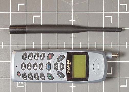
Click to zoom
Application Details
- Equipment Class
- DSS - Part 15 Spread Spectrum Transmitter
- Date of Grant
- Jul 04, 2002
- Application Purpose
- Original Equipment
- Date of Application
- Mar 18, 2002
- Equipment Note
- SR-436 Wireless Spread Spectrum Communications System
- Frequency Range
- 2400.00000000 - 2483.50000000
- Company
- SuperTel Technologies Inc
- Country
- United States
Documents & Files
Document Text
Text extracted from the exhibit documents filed with the FCC. Open a document above to read the original.
Users Manual
User’s Manual SR-436 4-line Wireless Telephone System 2 Table of Contents Safety Instructions ..................................................... 4 General Safety Instructions ..................................... 4 Product Safety Instructions ..................................... 5 Battery Safety Instructions ...................................... 8 Regulatory Information ............................................... 9 Congratulations ....................................................... 12 Equipment Checklist ................................................ 13 Handset Illustration .................................................. 14 Handset Features .................................................... 15 Basic Handset Features ....................................... 15 Additional Handset Features ................................. 17 Base Illustration ....................................................... 22 Base Features ......................................................... 23 Basic Base Station Features ................................. 23 Additional Base Station Features .......................... 24 Administrator Features ......................................... 25 Charger Illustration .................................................. 27 Charger Features .................................................... 28 Getting Started ........................................................ 29 Base Station Installation ....................................... 29 Handset and Charger Installation .......................... 31 Basic Operations ..................................................... 32 Making a Telephone Call ...................................... 32 Making an Intercom Call ....................................... 32 Redial .................................................................. 33 Receiving a Telephone Call .................................. 33 Receiving an Intercom Call ................................... 34 Ending a Call: ....................................................... 35 Adjusting Receiver Voice Volume ......................... 35 Placing a Call On Hold ......................................... 35 Mute .................................................................... 36 Do Not Disturb (Silent Ring) .................................. 36 Key Guard ........................................................... 37 3 Battery Recharge and Replacement ..................... 37 Advanced Operations .............................................. 39 Handset Registration ............................................ 39 Advanced Registration: ........................................ 40 Handset Group Subscription ................................. 42 Call Transfer ........................................................ 43 3-Way Conferencing ............................................. 44 Call Forwarding .................................................... 45 Auto-Attendant (AA) ............................................. 47 Call Waiting .......................................................... 48 AA Configuration by Administrator ........................ 49 Change System Settings by Administrator ............ 51 Phonebook Operations ......................................... 52 Menu Operations .................................................. 56 Text Messaging .................................................... 61 Technical Specifications Error! Bookmark not defined. 4 Safety Instructions Caution : Your wireless telephone gives you freedom and flexibility to stay in touch while you move around.However, the safe and responsible use of the phonedepends entirely on you.When using your phone equipment, safety instructionsshould be followed to avoid the risk of fire, electricshock, injury to person, and damage to property.General Safety Instructions1. When using your wireless phone, ensure your safety and the safety of others:a. Always watch where you are walking and standing. b. Don’t let a phone call distract you from working safely. 2. In an emergency: a. If an emergency occurs, dial the emergency phone number. Remember: if you are in anarea where your phone does not have a clearsignal from the base, it is highly probable thatthe call may not go through. Locate the nearestlandline telephone or other communicationsdevice to call for help. b. Emergency calls may not automatically provide emergency personnel with your name, phonenumber or location. Tell the operatori) Your name and phone number ii) The nature of the emergency iii) Whether police, fire, or medical assistance isneeded 5 iv) The exact location of the emergency,including address, cross streets, mileposts orlandmarks. 3. Notice to Hearing Aid Users: This phone system is compatible with inductively coupled hearing aids. 4. Notice to Cardiac Pacemaker Users: Preliminary studies done by the US FDA and others haveshown that, although interference to the implantedcardiac pacemaker may occur when operating veryclosely, wireless telephones “do not seem to pose asignificant problem for pacemaker wearers.”However, until more is known, FDA suggests thatpeople with pacemakers may want to takeprecautions when using or carrying a wirelesstelephone to ensure that there is ample distancebetween the telephone and the pacemaker. Do notcarry the handset in a breast pocket. If you haveany reason to suspect that interference is takingplace, turn off your handset immediately. Product Safety Instructions1. Read and understand all instructions.2. Follow all warnings and instructions including those marked on the product. 3. Changes or modifications to this product not expressively approved by the manufacturer will voidthe warranty and the FCC authorization to operatethe equipment. Use only manufacturer providedaccessories. 4. Do not use the telephone near water. Never spill liquid of any kind on this product. 5. Unplug the product from the wall telephone jack and power outlet before cleaning. Do not use liquid oraerosol cle…
Text truncated - open the document above for the full version.
Users Manual
Product Safety Instructions1. Read and understand all instructions.2. Follow all warnings and instructions including those marked on the product. 3. Changes or modifications to this product not expressively approved by the manufacturer will voidthe warranty and the FCC authorization to operatethe equipment. Use only manufacturer providedaccessories. 4. Do not use the telephone near water. Never spill liquid of any kind on this product. 5. Unplug the product from the wall telephone jack and power outlet before cleaning. Do not use liquid oraerosol cleaners. Use damp cloth for cleaning. 6. Do not place this product on an unstable cart, stand or table. The product may fall and cause personalinjury or damage to the product or other property.Place the base station and the charger on hard, flatsurfaces. 7. Power Outage: In the event of a power outage, your handsetcharger will not recharge the handset battery, andthe base station will not allow you to make anoutgoing call or take an incoming call. Both thecharger and the base station require electricity foroperation. You should have a telephone that does not require electricity available for use during poweroutage, or have a temporary backup power supply. 8. Slots or openings in the product’s housing are provided for ventilation. These openings must notbe blocked or covered. Placing the product on abed, carpeting, or other similar surface may blockthese openings and should be avoided. Thisproduct should never be placed near or over a 2 radiator or heat register, or in a built-in installationunless proper ventilation is provided. 9. Never push objects of any kind into this product through housing slots/openings as they maydamage the product, touch dangerous voltagepoints or short out parts that could result in fire,electric shock, or injury. 10. This product should be operated only from the type of power source indicated on the marking label. Ifyou are not sure of the type of power supply to yourhome, consult your dealer or local power company. 11. Do not overload wall power outlets and extension cords as this may result in fire or electric shock. 12. To avoid electric shock or burn, do not disassemble this product. Send this product to an authorizedservice center when service or repair work isrequired. Call Customer Service for locations nearyou. Opening or removing covers may expose youto dangerous voltages, electrical currents or otherrisks. Incorrect reassembling of the product maycause electric shock when the product issubsequently used. 13. Avoid using the product during a storm. There may be a risk of electric shock from lightning. 14. Do not place the product where persons can step, trip, or fall on the product. 15. Do not place conductive objects over or near the antenna. 16. Do not use the product to report a gas leak while in the vicinity of the leak. 17. Do not install the base station or the handset charger near microwave ovens, radios, TV sets,speakers, or other electrical equipment. Theseappliances may cause interference to the product orexperience interference from the product. 3 18. Unplug the base station or the charger adaptor from the wall power outlet and refer servicing to anauthorized service center under the followingconditions:a. If liquid had been spilled into the product.b. When the power supply cord or plug is damaged or frayed. c. If the product has been exposed to rain or water.d. If the product does not operate normally by following the operating instructions. e. If the product has been dropped or housing has been damaged. f. If the product shows a distinct change in performance. 19.This equipment is a transmitter that produces RF energy. The limits on human exposure to radioemission are set by FCC, this equipment complieswith those limits. The use of any accessories thathave not been approved is a violation of FCC rules. 20.The base is a mobile device and 20cm separation distance must be maintained between the end user and the antenna.
Cover Letter(s)
3245 146 th Place SE Suite 370 Bellevue, WA 98007 U.S.A. Telephone: +1-425-401-9600 Fax: +1-425-401-9614 1 January 17, 2002 Federal Communications Commission 7435 Oakland Mills Road Columbia, MD 21046 Gentlemen: This letter is to comply with Section 0.457(d)(2)(i) pertaining to confidential material. SuperTel Technologies, Inc., would like the following documents regarding this submission for FCC ID: NNA-SR-436 to be kept confidential. 1. Block Diagrams 2. Schematics The above material contains trade secrets or technical data, which would customarily be guarded from competitors. We do not want these documents to be accessible to the general public. Sincerely, Jyun-cheng Chen, Ph.D. President.
Cover Letter(s)
Response to EA753538 1. The customer says that SAR testing is not required. The handset's average output power is less than 80 mW, which is much less than the 300 mW guideline given in FCC OET-65 document . 2. The schematics are readable if you use the zoom feature in Word and increase the size to 500%. Please let me know if this is not acceptable. 3. A new test report has been uploaded.
Cover Letter(s)
1 SR-436 Fixed Terminal (FT) System Configuration and Functional Block Diagram An SR-436 Fixed Terminal (FT) is used to connect a standard analog telephone a PSTN (Public Switched Telephone Network) telephone line via the SR-436 Wireless Spread Spectrum Communications System as illustrated in the figure below. PSTN Public switch SR-436 BS RJ11 SR-436 FT Telephone SR-436 Fixed Terminal configuration The Telephone set on the FT side can be any standard analog telephone, a payphone, or a Group 3 fax machine. The base station connects to the PSTN through a standard 2-wire RJ-11 telephone plug. Other than the external (outdoor) antenna on either or both side of the BS and FT, the system is plug-and-play. The external (outdoor) antenna can be used on either or both the BS and FT to achieve maximum range although it is not required. A standard antenna can be used if the desired range can be achieved without the outdoor antenna. Fixed Terminal (FT) The function of SR-436 Fixed Terminal is to connect the user terminal to the PSTN via a wireless link with the base station, in essence providing a wireless phone jack. The fixed terminal base band circuitry consists of two processors: one DSP and one μC. The DSP handles the air interface and physical layer signal processing. It communicates with the IF Sampler (a combined A/D and D/A). The IF Sampler converts baseband digital samples from the DSP into a 10.7MHz analog signal and passes onto the RF module for transmitting. On the receive side, it receives 10.7 MHz analog signals from the RF module, converts it into digital samples, and forwards them 2 to the DSP for processing. A receive 10.7 MHz filter is located on the base-band board to eliminate noise and adjacent channel interference. The DSP is also responsible for voice compression and decompression (vocoder). Voice data from the codec must be compressed by the vocoder inside the DSP before transmission. On the receive path, voice data must be decompressed before being sent to the codec. The codec is connected to the DSP by a full duplex serial port. The analog side of the codec is connected to an ordinary telephone through a subscriber line interface circuit, SLIC. The μC tracks the state of the fixed terminal, including the on/off hook status of the user terminal and the air link and controls the ringing state of the SLIC IC. It also keeps system configuration data in the EEPROM. Other major sub-systems include: • Clock Generator (16.384 MHz / 8.192 MHz): Generates 16.384 MHz clock for the DSP and the RF module. An 8.192 MHz clock, used by the μC as its system clock, is derived from the 16.384 MHz. • IF Sampler (MAX1005): Performs D-to-A function during transmit and A-to-D function during receive. • SLIC (Subscriber Line Interface Circuit): Performs the standard feeding, signaling and transmission functions for subscriber. • Metering Pulse Generator: Clock source for SLIC metering pulse output (12 KHz or 16 KHz). The DC power input shall be 9.0V nominal. It’s preferable that the wall adapter shall be a linear regulator, not a switching regulator (for improved noise performance). The subscriber side of the line interface (SLIC) contains a PTC and MOV for protection. 3 FT block diagram External Antenna The external antenna can be mounted on the Base Station and/or Fixed Terminal. It is supplied with a 20-meter coax cable that has unique connectors at both ends. The gain of the antenna is a 6dBi gain antenna. The cable is 20 meters long with a loss of 9db at 2.4GHz.
Cover Letter(s)
SuperTel Technologies, Inc. 3245 146 th Place SE, Suite 370 Bellevue, WA 98007 June 20, 2002 Mary Ellen CKC Laboratories, Inc. 5473A Clouds Rest Mariposa, CA 95338 Tel: (800) 500-4362 Dear Ms. Ellen: I am writing to respond to your e-mail inquiry dated June 19, 2002, about SAR, average transmit power and transmit duty cycle in our products, SR-436, which are in the process of FCC Part 15 certification. 1. Handset SAR: According to the guidelines in Supplement C to OET-65, Section 3, Table 1, the limit for a 2450 MHz handset transmitter is 0.2W. In addition, Footnote 19 states: “When applicable, a source-based time-averaging duty factor may be considered for determining compliance.” SR-436 employs TDMA multiple access scheme and the handset has a duty cycle of 12% (see detailed explanation below). With a design peak power of 500 mW, the average power is only 60 mW , thus meeting the SAR requirement. 2. Average Power: To accommodate 4 users per RF carrier (to handle 4 C.O. lines), SR-436 uses a 8-slot TDMA scheme with a frame length of 10 ms. The uplink (handset to base) frame and slot structures are shown as below: RX1T/R Switching RF Hopping Settling Data (98 bits)Sync (20 bits)Guard (10 bits) RX4RX3RX2 TX1TX4TX3TX2 10 ms 1.20 ms Data (77 bits) where • Frame length is 10 ms, and the hopping rate is 100 hops/second, i.e., one frame per hop. • TX1-TX4 time slot is 1201.17 μ s each, for a duty cycle of 12 % . • RF switching time is 199.87 μ s. • RX1-RX4 time slot is 1142.58 μ s. • RF hopping settling time is 425.13 μ s. • Speech codec is 8 kbps G.729A, FEC adds 8 kbps, there are 15 signaling bits per slot. • System Clock Frequency, Clk = 16.384 MHz • Internal DSP Clock Frequency, ClkDsp = Clk x 6 = 98.304 MHz • Digital to Analog sample rate is 8.192 MHz (i.e. 12 DSP clock) • Number of samples per transmitted bit = 48. • Bit period, Tb = (1/ClkDsp) x 576 = 5.859 μ s. • Channel data rate is 170.667 kbps. Attached plot in Figure 1 illustrates the duty cycle of an SR-436 handset. 3. Base SAR: According to the guidelines in Supplement C to OET-65, Section 3, Table 1, the limit is 4W for a 2450 MHz mobile transmitter using indoor antenna that operates at 20 cm or more from nearby persons. On the reverse link (base to handset) of SR-436, the base station’s total transmit time is 1.14258 ms x 4 = 4.57032 ms, for a duty cycle of 45.7% . Therefore, with a design peak power of 500 mW, the average power is 0.22W , less than the 4 W limit for a mobile unit. The base station’s frame and slot structures are: TX1T/R Switching RF Hopping Settling Voice Data (98 bits)Sync (20 bits)Voice Data (77 bits) TX4 TX3 TX2RX1RX4RX3RX2 10 ms 1.14 ms Attached plot in Figure 2 illustrates the duty cycle of an SR-436 Base. 4. Safety Statements: The following statement will be added to Item 19 on Page 7 of the User’s Manual: "This equipment is a transmitter which produces RF energy. The limits on human exposure to radio emission are set by FCC, this equipment complies with those limits. The use of any accessories that have not been approved is a violation of FCC rules." 5. Belt Clip: Attached in Figure 3 is a photo of the Belt Clip used in SR-436. I appreciate your assistance in this application; please feel free to contact me if you have any question. Best regards, J. C. Chen, Ph.D. Tel: (425) 401-9600 x 1834 Fax: (425) 401-9614 E-mail: [email protected] Figure 1: SR-436 Handset duty cycle illustration. Figure 2: SR-436 Base Station duty cycle illustration. Figure 3: SR-436 Belt Clip.
External Photos
Base Unit Hand held Fixed Ter minal
Internal Photos
Base Unit Hand held Fixed Ter minal Fixed Ter minal
Operational Description
• Description of circuitry: SR-436 RF Section: (i) Receiver path: The signal enters the device at the antenna port into an impedance matching circuit and a band-pass filter comprising of L802, C811, C807, C808, L804, F801, C810, C809, L803, C805 and C806. This has a band pass filter of 83MHz centered on 2441.5MHz. Then via a T/R switching circuit comprising of U801 and C802 into a low noise amplifier whose active component is Q601. The signal then goes into U602. The U602 contains two amplifiers and a mixer. The signal is filtered once again with a filter with pass band 2450 ± 50MHz (F602) after the two amplifiers in U602. Mixer in U602 down converts the 2403 –2480 MHz signal down to the first IF frequency of 315 MHz. It is then filtered by SAW filter (F603). It then goes into U601 which is a second IF chip. Here it is down converted to 10.7MHz, amplified, filtered (F601) and limited. The received signal strength indicator (RSSI) is obtained from here. The 10.7MHz signal then goes into base-band board via pin 2 of J801. (ii) Transmit path: A 10.7 MHz signal is provided by the base-band board at pin 3 of J801. It is filtered by F501, which is a 10.7MHz filter. The 10.7MHz signal then passes to U501, which up converts the signal to 315 MHz. It is filtered by F502 (SAW filter) and LC filters (L503, C509, L526, C549 and C554). The signal is up again converted from 315 MHz to 2403 –2480 MHz by U502. It is further filtered by F503 which is a band pass filter centered on 2441.5MHz ± 41.5 MHz. U503 amplifies the signal, it passed through a band-pass filter (F504) before being amplified by U504 and Q501. The signal passes through the T/R switch and filter mentioned in the receive section to the antenna port. For the base station, its average RF power is 214 mW and its peak RF power is 500mW. For the portable handset, its average RF power is 54mW and its peak RF power is 500mW. (iii) Other sub circuits: A 16.384MHz is provided by the base-band board at pin 7 of J801 to U701. U701 is the heart of a frequency synthesizer, which provides the control of the dual oscillators. The first one oscillator is used in the up and down conversion of the signal from 10.7MHz to 315 MHz. The second one oscillator is also used in the up and down conversion of the signal from 315 MHz to 2403 –2480 MHz. The exact frequency used is controlled by the base-band board at pin 17, pin 18 and pin 19 of J801. (iv) Antenna: On the base station a 5-dBi antenna is used and this is attached to the antenna port via a reverse thread TNC connector. On the handset a 5-dBi and a 2-dBi antennas are used and those are attached to the antenna port via a non-standard connector.
Test Report
Page 1 of 105 Report No: FC02-010 SUPERTEL TECHNOLOGIES, INC. TEST REPORT FOR THE SR-436 WIRELESS SPREAD SPECTRUM COMMUNICATIONS SYSTEM FCC PART 15 SUBPART C SECTIONS 15.207 & 15.247 COMPLIANCE DATE OF ISSUE: MARCH 5, 2002 PREPARED FOR: SuperTel Technologies, Inc. 3245 146th Place SE, Suite 370 Bellevue, WA 98007 PREPARED BY: Mary Ellen Clayton CKC Laboratories, Inc. 5473A Clouds Rest Mariposa, CA 95338 P.O. No.: W.O. No.: STT-02-889 78247 Date of test: January 7 – Februrary 28, 2002 Report No.: FC02-010 This report contains a total of 105 pages and may be reproduced in full only. Partial reproduction may only be done with the written consent of CKC Laboratories, Inc. The results in this report apply only to the items tested, as identified herein. Page 2 of 105 Report No: FC02-010 TABLE OF CONTENTS Administrative Information .........................................................................................................5 Summary of Results.....................................................................................................................6 Conditions for Compliance ..........................................................................................................6 Approvals.....................................................................................................................................6 Equipment Under Test (EUT) Description ..................................................................................7 Eut Operating Frequency .............................................................................................................7 Mode Of Operation ......................................................................................................................7 15.31 Number Of Channels .........................................................................................................7 15.33 Frequency Ranges Tested ..................................................................................................7 15.203 Antenna Requirements.....................................................................................................7 15.205 Restricted Bands ..............................................................................................................7 15.215 Additional Provisions to the General Radiated Emission Limitations.............................7 Equipment Under Test .................................................................................................................8 Peripheral Devices .......................................................................................................................8 Report of Measurements ..............................................................................................................9 15.247(a)(1) Base - Channel Separation .........................................................................9 15.247(a)(1) Handset - Channel Separation....................................................................10 15.247(a)(1)(ii) Base - Bandwidth Low Channel ...........................................................11 15.247(a)(1)(ii) Base - Bandwidth Middle Channel .......................................................12 15.247(a)(1)(ii) Base - Bandwidth High Channel...........................................................13 15.247(a)(1)(ii) Handset - Bandwidth Low Channel ......................................................14 15.247(a)(1)(ii) Handset - Bandwidth Middle Channel..................................................15 15.247(a)(1)(ii) Handset - Bandwidth High Channel .....................................................16 15.247(a)(1)(ii) Base Average Occupancy .....................................................................17 15.247(a)(1)(ii) Handset Average Occupancy ................................................................18 15.247(a)(1)(ii) Base Number Of Hops ..........................................................................19 15.247(a)(1)(ii) Base Number Of Hops ..........................................................................20 15.247(a)(1)(ii) Handset Number Of Hops.....................................................................21 15.247(a)(1)(ii) Handset Number Of Hops.....................................................................22 15.247(a)(1)(ii) Base On Time .......................................................................................23 15.247(a)(1)(ii) Handset On Time ..................................................................................24 Table 1: 15.247(b)(1) Base Set Highest Peak Output: EIRP ..........................................25 Table 2: 15.247(b)(2)/15.31(e) Base Set Voltage Variation on Peak Power ..................26 Table 3: 15.247(c)/15.209 Base Set OATS Highest Emission Levels: 3MHz-25GHz............. 27 Table 4: 15.247(c) Base Set Terminal Highest Emission Levels: 9kHz-10GHz ............28 15.247(b)(1) Base Peak Output Antenna Terminal - Low..............................................29 15.247(b)(1) Base Peak Output Antenna Terminal - Middle..........................................30 15.247(b)(1) Base Peak Output Antenna Terminal - High .............................................31 Table 5: 15.247(b)(1) Hand Set Highest Peak Output: EIRP .........................................32 Table 6: 15.247(c)/15.209 Hand Set OATS Highest Emission Levels: 15MHz-26GHz.33 Table 7: 15.247(c) Hand Set Terminal Highest Emission Levels: 9kHz-10GHz ...........34 Page 3 of 105 Report No: FC02-010 15.247(b)(1) Handset Peak Output Antenna Terminal - Low.........................................35 15.247(b)(1) Handset Peak Output Antenna Terminal - Middle ....................................36 15.247(b)(1) Handset Peak Output Antenna Terminal - High ........................................37 Table 8: 15.247(b)(1) Fixed Terminal Highest Peak Output: EIRP ...............................38 Table 9: 15.247(b)(1)/15.31(e) Fixed Terminal Voltage…
Text truncated - open the document above for the full version.
Test Setup Photos
PHOTOGRAPH SHO WING ANTENNA CONDUCTED EMISSIONS - BASE PHOTOGRAPH SHOWING RADIATED EMISSIONS Radiated Emissions - Front View - SR-436 Base and Charger PHOTOGRAPH SHOWING RADIATED EMISSIONS Radiated Emissions - Back View - SR-436 Base and Charger PHOTOGRAPH SHO WING ANTENNA CONDUCTED EMISSIONS - HANDSET PHOTOGRAPH SHOWING RADIATED EMISSIONS Radiated Emissions - Front View - SR-436 Handset Vertical PHOTOGRAPH SHOWING RADIATED EMISSIONS Radiated Emissions - Front View - SR-436 Handset Horizontal PHOTOGRAPH SHOWING RADIATED EMISSIONS Radiated Emissions - Back View - SR-436 Handset Vertical PHOTOGRAPH SHOWING RADIATED EMISSIONS Radiated Emissions - Back View - SR-436 Handset Side PHOTOGRAPH SHO WING MAINS CONDUCTED EMISSIONS Mains Conducted Emissions - Front View - SR-436 PHOTOGRAPH SHO WING MAINS CONDUCTED EMISSIONS Mains Conducted Emissions - Side View - SR-436 PHOTOGRAPH SHOWING RADIATED EMISSIONS Radiated Emissions - Front View - SR-436-FT PHOTOGRAPH SHOWING RADIATED EMISSIONS Radiated Emissions - Back View - SR-436-FT PHOTOGRAPH SHO WING VOLTAGE VARIATION AT ANTENNA TERMINAL Voltage Variation - Front View - SR-436-FT PHOTOGRAPH SHO WING MAINS CONDUCTED EMISSIONS Mains Conducted Emissions - Front View - SR-436-FT PHOTOGRAPH SHO WING MAINS CONDUCTED EMISSIONS Mains Conducted Emissions - Side View - SR-436-FT
Contact Information
Applicant
J.C. Chen(President)
Non-Technical Contact
CKC Laboratories, Inc.Mary Ellen Clayton
[email protected]290-966-5240
Test Firm
CKC Laboratories, Inc.Steve Behm
Technical Specifications
| # | Rule Parts | Frequency Range | Power Output |
|---|---|---|---|
| 1 | 15C | 2.40 GHz - 2.48 GHz | 429.00 mW |
Other Applications from SuperTel Technologies Inc
NNA-EP-436
Jul 04, 2002EP-436 4-Line Wireless Telephone System
Equipment Class
DSS - Part 15 Spread Spectrum Transmitter
NNA-SN-900U
Nov 11, 1998900 MHz Cordless Phone
Equipment Class
DSS - Part 15 Spread Spectrum Transmitter