NNOMODEL2000Server Call System
Discovery Corps Inc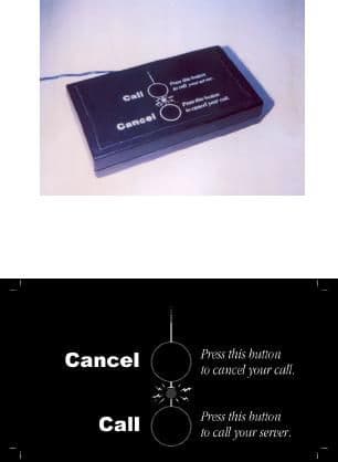
Click to zoom
Application Details
- Equipment Class
- DXX - Part 15 Low Power Communication Device Transmitter
- Date of Grant
- Mar 02, 2000
- Application Purpose
- Original Equipment
- Date of Application
- Dec 06, 1999
- Equipment Note
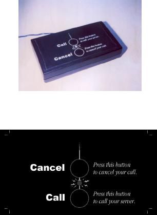
- Server Call System
- Frequency Range
- 315.00000000 - 315.00000000
- Company
- Discovery Corps Inc
- Country
- United States
Documents & Files
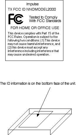
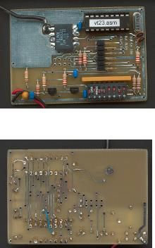
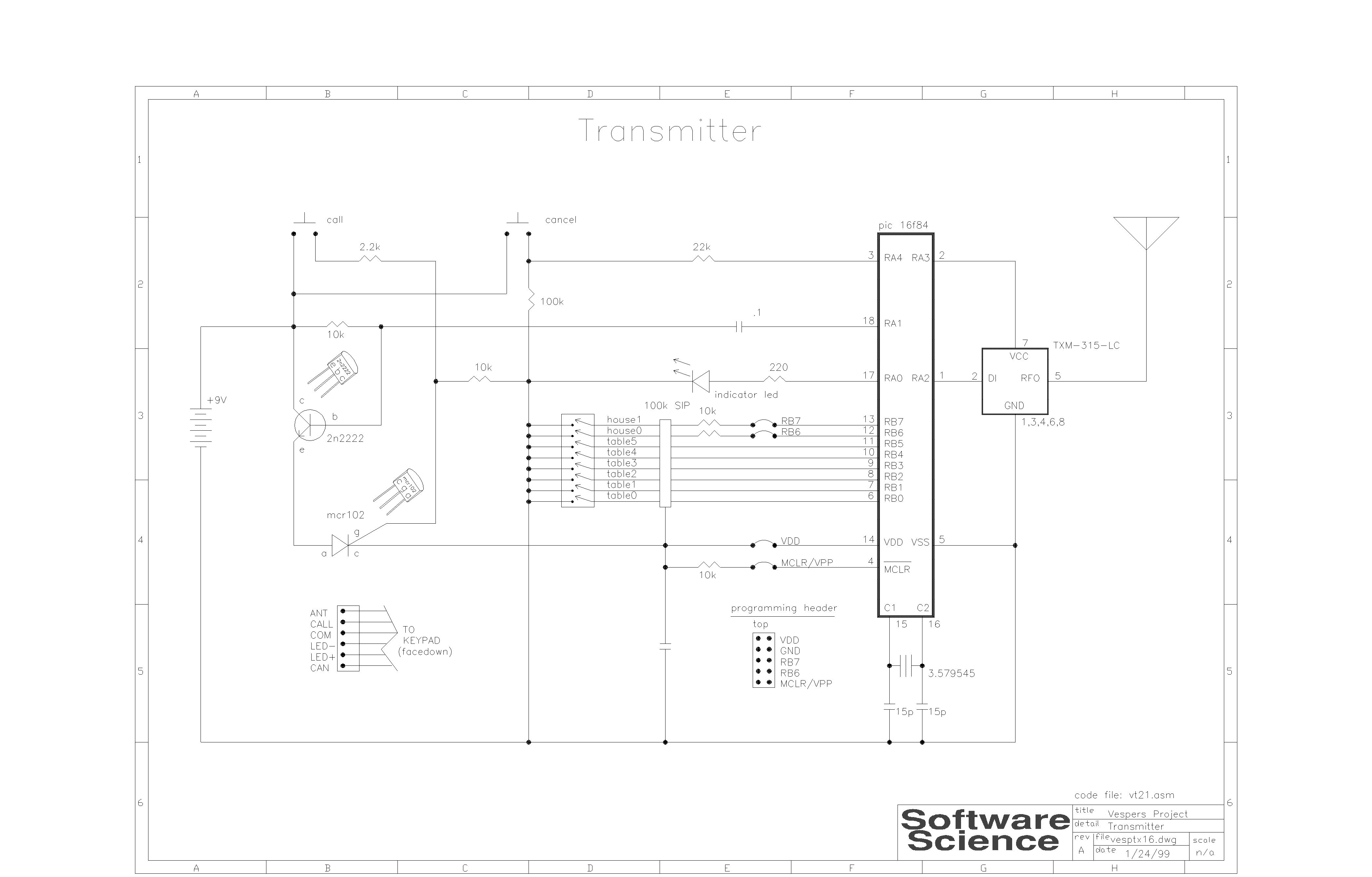
Document Text
Text extracted from the exhibit documents filed with the FCC. Open a document above to read the original.
Test Report
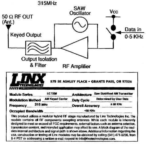
This report shall not be reproduced, in whole or in part without the written approval of Test Site Services Inc. This report must not be used by the recipient to claim product endorsement by NVLAP or any other agency of the U.S. Government Test Site Services. Inc. EMI Test Report For Discovery Corps,Inc. "Impulse" Transmitter Model 01 Radiated Emissions FCC, Part 15C Test # B90323 Test Site Services, Inc. P.O. Box 766 Marlboro, MA 01752 U.S.A. Phone/Fax: (508) 481-1684 Test Site Services, Inc.Report # B90323 Discovery Corps,Inc.08/19/99EUT: "Impulse" Transmitter Table of Contents GENERAL INFORMATION..................................................................................................................................................1 EQUIPMENT UNDER TEST DESCRIPTION.......................................................................................................................3 TEST SUMMARY..................................................................................................................................................................4 BLOCK DIAGRAM...............................................................................................................................................................5 BLOCK DIAGRAM DESCRIPTION......................................................................................................................................6 PROGRAM DESCRIPTION...................................................................................................................................................7 MODES OF OPERATION......................................................................................................................................................7 TEST EQUIPMENT LIST......................................................................................................................................................8 APPENDIX A, TEST DATA................................................................................................................................................A1 APPENDIX B, TEST PHOTOGRAPHS...............................................................................................................................B1 APPENDIX C, TEST PROCEDURES..................................................................................................................................C1 APPENDIX D, MEASUREMENT FACILITIES INFORMATION.......................................................................................D1 Test Site Services, Inc.Report # B90323page 1 of 8 Discovery Corps,Inc.08/19/99EUT: "Impulse" Transmitter Test Site Services, Inc.Report # B90323page 2 of 8 Discovery Corps,Inc.08/19/99EUT: "Impulse" Transmitter Administrative Data Regulation : FCC, Part 15C (U.S.) : 15.201 b, 15.209 a,c, 15.215 a,b, 15.231a,b,c Level : Class A Test Method : ANSI C63.4-1992 Test Type : Qualification Manufacturer : Discovery Corps,Inc. EUT Type/Model # : "Impulse" Transmitter / 01 Date(s) of Test : 08/19/99 Customer Personnel : Sean RomePresident TSS Personnel : R. WiedemanEMC Engineer : Tom Charron : Bob Quinn : Walt Luczkow Test Engineer Test Engineer Test Engineer Test Location: Open Area Test Site Test Site Services, Inc. 30 Birch St. Milford, MA 01757 U.S.A. NOTICE: FCC Rule 2.955 requires that a Verification Report for a Class A Computing Device must be signed by "an Official of the Company responsible for the device". A signature block has been provided on the first page for this purpose. Test Site Services, Inc.Report # B90323page 3 of 8 Discovery Corps,Inc.08/19/99EUT: "Impulse" Transmitter EUT Description The EUT ("Impulse" Transmitter) is a Battery powered transmitter and pager used in restaurants to summon waitstaff. A complete description of the EUT may be found on block identifier page one. The tests were run in a typical configuration including the following support equipment; 1)Transmitter REASON FOR TEST Certificationfor FCC CHANGES MADE DURING TEST 1)Trimmed Antenna on Transmitter to 5 inches DEVIATIONS FROM STANDARD TEST METHOD None Test Site Services, Inc.Report # B90323page 4 of 8 Discovery Corps,Inc.08/19/99EUT: "Impulse" Transmitter Test Summary The "Impulse" Transmitter complied with the FCC Part 15 Subpart C 15.209 a,c, 15.215 b, 15.231 b Limits for equipment when tested in the system configuration defined herein. The following table indicates the margins (i.e. difference between measurement point and limit) of the six (6) worst case data points: TEST CLASSMARGIN TO SPEC (db)FREQUENCY (Mhz) Fundamental / Harmonics-2.5315.03 FCC 15.231 b-4.0630.05 315.03 – 3151.25 MHz.-4.41260.10 -4.82520.19 -6.02835.22 -6.03151.25 Spurious Emissions-17.61.7988 FCC 15.209 a, c, 15.215 b-18.43.5790 150 kHz. – 30 MHz.-23.65.3960 -24.27.1950 -28.38.9940 -29.912.5920 Spurious Emissions-15.6660.0 FCC 15.209 a, c, 15.215 b-16.5590.0 30 MHz. – 1 GHz.-16.7500.0 -17.2275.0 -17.6430.0 -19.2315.03 Bandwidth FCC 15.231cBW < 50 kHz.Requirement is < 787.5 kHz. Test Site Services, Inc.Report # B90323page 5 of 8 Discovery Corps,Inc.08/19/99EUT: "Impulse" Transmitter Block Diagram for "Impulse" Transmitter PS = Power Cord Shielded DS = Data Cable Shielded CX = Coaxial Cable PU = Power Cord Unshielded DS = Data Cable Shielded FL = Fiber Link = Ferrite Bead = Connector Ground Plane Control Room Test Site Services, Inc.Report # B90323page 6 of 8 Discovery Corps,Inc.08/19/99EUT: "Impulse" Transmitter EUT Technical Data – Block Identifier 1 Description : “Impulse” Transmitter Manuf/Model: Discovery Corps,Inc.Model No.: :01 Part#/Rev : 01 Serial # : N/A Power (Rated) : 9 VDC (Battery) Power (Tested) : 9 VDC (Battery) Internal Options: None External Options: None Frequencies Generated: 3.579545 MHz. 315.00 MHz. Comments: Test Site Services, Inc.Report # B90323page 7 of 8 Discovery Corps,Inc.08/19/99EUT: "Impulse" Transmitter Program Description TITLE:Impulse PART #/REV.:1.0 FUNCTION :To transmit call signal and cancel sign…
Text truncated - open the document above for the full version.
Test Setup Photos
Test Setup Photos The test setup photos are included in the Test Report PDF file.
Contact Information
Applicant
Sean Rome(President)
Technical Contact
Discovery Corps, Inc.Sean V Rome
[email protected]513 871 0030
3436 St. John Pl. · Cincinnati, Ohio · United States
Non-Technical Contact
Discovery Corps, Inc.Sean V Rome
[email protected]513 871 0030
Technical Specifications
| # | Rule Parts | Frequency Range | Power Output | Tolerance |
|---|---|---|---|---|
| 1 | 15C | 315 MHz - 315 MHz | - | Hz |