NO9M40004Crane Remote Control Transmitter
HBC-radiomatic GmbH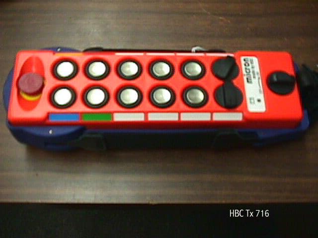
Click to zoom
Application Details
- Equipment Class
- DXX - Part 15 Low Power Communication Device Transmitter
- Date of Grant
- Sep 16, 2001
- Application Purpose
- Original Equipment
- Date of Application
- Sep 16, 2001
- Equipment Note
- Crane Remote Control Transmitter
- Frequency Range
- 902.30000000 - 918.00000000
- Company
- HBC-radiomatic GmbH
- Country
- Germany
Documents & Files
Document Text
Text extracted from the exhibit documents filed with the FCC. Open a document above to read the original.
Users Manual
Operating Instructions Radio Transmitter micron 4 Industrial BE-MICR4_I-V2-2.DOC [ Word 97 ] FLPage 1 / 18 HBC-radiomatic GmbH • D-74564 Crailsheim • GERMANY Information and specifications subject to change without notice.2000-08-15 Radio System HBC – Radio Controls R R a a d d i i o o T T r r a a n n s s m m i i t t t t e e r r m m i i c c r r o o n n 4 4 Industrial STOP micron made by HBC 01 31.394 11 22 P I T C H C A T C H T r o l l e y 1 1 + 2 2 Operating Instructions Radio Transmitter micron 4 Industrial Page 2 / 18BE-MICR4_I-V2-2.DOC [ Word 97 ] FL HBC-radiomatic GmbH • D-74564 Crailsheim • GERMANY 2000-08-15Information and specifications subject to change without notice. Radio System Manufacturer :HBC-radiomatic GmbH Haller Straße 49 - 53 74564 Crailsheim • GERMANY Tel. +49 ( 0 ) 79 51 – 3 93 - 0 Fax +49 ( 0 ) 79 51 – 3 93 – 50 E-mail: [email protected] http://www.hbc-radiomatic.com HBC radiomatic GmbH is not liable for any misprints or errors! – All rights reserved. ™radiomatic is a registered German trademark. ©2000 – 08 , HBC-radiomatic GmbH , D-74564 Crailsheim No part of any software or of the present document may be reproduced in any manner whatsoever without the expressed written permission of HBC-radiomatic GmbH. Operating Instructions Radio Transmitter micron 4 Industrial BE-MICR4_I-V2-2.DOC [ Word 97 ] FLPage 3 / 18 HBC-radiomatic GmbH • D-74564 Crailsheim • GERMANY Information and specifications subject to change without notice.2000-08-15 Radio System Table of Contents 1Description...................................................................................4 2Safety Instructions........................................................................5 2.1Pictographs.......................................................................................5 2.2General Safety Instructions................................................................6 2.3Operator Safety Instructions..............................................................7 3Operation......................................................................................8 Scanner (Frequency Selector)............................................................9 3.1Battery and Battery Charger.............................................................10 3.1.1FuB 3A Transmitter Battery.................................................10 3.1.2FLG 105 Battery Charger.....................................................10 3.2Special Operating Modes (Optional).................................................11 3.2.1Pitch – Catch......................................................................11 3.2.2Pitch – Catch – Tandem Mode.............................................13 4Fault Correction..........................................................................15 5Maintenance................................................................................16 5.1In the Event of a Fault......................................................................16 6Technical Data............................................................................17 Accessories.....................................................................................17 6.1Dimensions and Operator Controls of micron 4................................18 Operating Instructions Radio Transmitter micron 4 Industrial Page 4 / 18BE-MICR4_I-V2-2.DOC [ Word 97 ] FL HBC-radiomatic GmbH • D-74564 Crailsheim • GERMANY 2000-08-15Information and specifications subject to change without notice. Radio System 1Description The micron 4 transmitter is designed to transmit command instructions for controlling industrial cranes and hoists as well as operating machines and plants. Depending on the type and version selected, up to 24 control commands plus the integrated STOP commands are available to the operator. A non-interchangeable system address ensures the functional safety of the radio control system when operating cranes or machines. This feature is particularly important when several cranes or machines are in use, for example in halls and shops. The system address is exclusively allocated to each HBC radio transmitter and its respective receiver. It is not possible to activate crane or machine functions using a radio control system allocated to another crane or machine. The radio control system consists of the micron 4 transmitter, two rechargeable NiCd batteries, a battery charger and a receiver with antenna. The receiver housing with integrated antenna is made of ABS plastic. The micron 4 is a hand-held transmitter. The observance of handling instructions ensures operator and worker safety as well as preventing transmitter wear. The transmitter is powered by 2 rechargeable batteries. The batteries and memory effect-free battery charger are included. The transmitter has general telecommunications approvals. It is not necessary to have or to apply for a license to operate the micron 4 transmitter with the respective receiver. The transmitter must be operated in the 433,100 MHz to 434,750 MHz range or 869 MHz to 870 MHz bandwidth. The transmitter is equipped with < 10 mW (average) transmitting power. Operating the micron 4 using a different frequency range or transmitting power requires the approval of the competent regulative authorities for telecommunication. The following radio receivers may be used in conjunction with the micron 4 transmitter: FSE 716FSE 722 BFSE 735 Note: The improper use, operation or deployment of the device renders the manufacturer guarantee void of any legal substance! Operating Instructions Radio Transmitter micron 4 Industrial BE-MICR4_I-V2-2.DOC [ Word 97 ] FLPage 5 / 18 HBC-radiomatic GmbH • D-74564 Crailsheim • GERMANY Information and specifications subject to change without notice.2000-08-15 Radio System 2Safety Instructions 2.1Pictographs The following pictographs will be used throughout the present operating instructions : Indicates a possible shock hazard Contacting components under voltage may lead to death…
Text truncated - open the document above for the full version.
Users Manual
Operating Instructions Radio Transmitter micron 4 Industrial BEMIC4_V2-3_US-L.DOC [ Word 97 ] FL P age 7 / 18 HBC-radiomatic, Inc. , Cincinnati , Ohio 45242 , USA Information and specifications subject to change without notice.2001-05-16 Radio Control System 2.3Operator Safety Instructions ! Warning to our Users : In accordance to the rules and regulations of the FCC, any changes or modifications made to our transmitter or receiver by you without the express written consent of HBC-radiomatic, Inc. could void your authority to operate the equipment under FCC’s rule 15.21 ! ! Before beginning crane operation, position yourself so that you have a clear and complete overview of the working radius of the crane or machine. ! To operate, hold the transmitter securely in your hand. Use the optional wrist strap. Follow these instructions to ensure personal safety. ! Depending on your angle or position to the crane or machine, the transmitter control commands “trolley left” and “trolley right” appear to interchange ! It is essential that yo u take your bearings to the crane or machine into due consideration before operating equipment. ! In case of an emergency or any disturbances within the working range of the crane or machine, switch the transmitter OFF immediately by pressing the STOP pushbutton. Should the transmitter show signs of technical failure or breakdown, disconnect the radio control system immediately ! ! Switch the transmitter OFF during breaks and after finishing work to avoid any misoperation of crane or machine by unintended activation of the operator controls. – These precautions are particularly important whenever changing your position or climbing over an obstacle. ! Never leave an activated transmitter unattended. The operator undertakes to follow and comply with the authoritative regulations for worker safety and accident prevention (e. g. VBG 9). Note : – In the event of an interruption of the radio link during a working cycle – what can occasionally happen – both transmitter and receiver automatically shut down (so-called " compulsory switch-off "). To reactivate the system release all operator controls, such as pushbuttons or momentary contacts, and allow the control elements to return to their zero position. Press the "ON/Horn" pushbutton. The system must be reactivated before the crane or machine can react to control commands ! This feature hinders any uncontrolled or unwanted crane or machine movement, should the radio link be interrupted. – When operating a crane by means of a radio control system for the first time, you may miss the physical contact to the crane that you were used to in the operating stand. As you are no longer in the crane and can no longer sense the starting of the crane movements as distinctly, crane reactions will appear sluggish or dull.
Block Diagram
CAD-Zeichnung, keine manuellen Aenderungen! CAD drawing, no manual modification! D-74555 Crailsheim Postfach 1561 HBC-radiomatic GmbH Z.-Nr.: Doc.No.:Sheet Blatt Datum: Date: Datei: File: Geprueft/checked by: Gezeichnet/Drawn by: M.Metzger AA283A91.sbk29.06.2000 AA.283.A.911/1 MAINBOARD CASE MODULTRANSMITTER D.HahnTRANSMITTER MICRON 4 BLOCK DIAGRAMM BATTERY SWITCHES ENCODERMODUL
ID Label/Location Info
micron 4 2 1 Katze 1 1+2 2 File: MICRON4-I_Rueckseite.CDR [ CorelDraw 8.0 ] 15.12.2000 FL 236 mm ( 9.3 " ) 218 mm ( 8.6 " ) 87 mm ( 3.4 " ) 50 mm ( 2.0 " ) 65 mm ( 2.6 " ) 50 mm ( 2.0 " ) HBC-radiomatic GmbH Tel.: +49(0)7951/393-0 Made in Germany Prod.Code: micron 4 Transmitter Ser.No.: IP55 / Nema 4 U: 6V DC Frequency (MHz): 902,000918,000 Frequency Block: Batt. FCC ID: NO9M40004 CANADA: YYYY YYY YYYY – This device complies with part 15 of the FCC rules. Operation is subject to the following conditions: (1) This device may not cause harmful interference, and (2) this device must accept interference received, including interference that may cause undesired operation. This device complies with part 15 of the FCC Rules. Operation is subject to the following two conditions: (1) This device may not cause harmful interference, & (2) This device must accept any interference received, including interference received that may cause undesired operation. HBC-radiomatic GmbH Tel.: +49(0)7951/393-0 Made in Germany Prod.Code: micron 4 Transmitter Ser.No.: IP55 / Nema 4 U: 6V DC Frequency (MHz): 902,000918,000 Frequency Block: Batt. – micron:NO9M40004USA:CANADA:
Operational Description
Operating Instructions Radio Transmitter micron 4 Industrial Page 4 / 18BE-MICR4_I-V2-2.DOC [ Word 97 ] FL HBC-radiomatic GmbH • D-74564 Crailsheim • GERMANY 2000-08-15Information and specifications subject to change without notice. Radio System 1Description The micron 4 transmitter is designed to transmit command instructions for controlling industrial cranes and hoists as well as operating machines and plants. Depending on the type and version selected, up to 24 control commands plus the integrated STOP commands are available to the operator. A non-interchangeable system address ensures the functional safety of the radio control system when operating cranes or machines. This feature is particularly important when several cranes or machines are in use, for example in halls and shops. The system address is exclusively allocated to each HBC radio transmitter and its respective receiver. It is not possible to activate crane or machine functions using a radio control system allocated to another crane or machine. The radio control system consists of the micron 4 transmitter, two rechargeable NiCd batteries, a battery charger and a receiver with antenna. The receiver housing with integrated antenna is made of ABS plastic. The micron 4 is a hand-held transmitter. The observance of handling instructions ensures operator and worker safety as well as preventing transmitter wear. The transmitter is powered by 2 rechargeable batteries. The batteries and memory effect-free battery charger are included. The transmitter has general telecommunications approvals. It is not necessary to have or to apply for a license to operate the micron 4 transmitter with the respective receiver. The transmitter must be operated in the 433,100 MHz to 434,750 MHz range or 869 MHz to 870 MHz bandwidth. The transmitter is equipped with < 10 mW (average) transmitting power. Operating the micron 4 using a different frequency range or transmitting power requires the approval of the competent regulative authorities for telecommunication. The following radio receivers may be used in conjunction with the micron 4 transmitter: FSE 716FSE 722 BFSE 735 Note: The improper use, operation or deployment of the device renders the manufacturer guarantee void of any legal substance!
Test Report
Report of Equipment Authorization for the Micron 4 Transmitter Certified under the FCC Rules contained in Title 47 of the CFR, Part 15, Subpart B 15.249 for 902-928 MHz Operation MET REPORT EMC1308B August 20, 2001 PREPARED FOR: HBC-Radiomatic Haller Strasse 49-53 D-74564 Crailsheim, Germany PREPARED BY: MET Laboratories, Inc. 914 West Patapsco Avenue Baltimore, Maryland 21230-3432 August 20, 2001 HBC-Radiomatic Haller Strasse 49-53 D-74564 Crailsheim, Germany Attention:Juergen Schneider Regarding:Certification of the Micron 4 Transmitter under Part 15, Subpart B of the FCC Rules as a Transmitter MET Report: EMC1308B Dear Juergen Schneider: Enclosed is a report of compliance in accordance with FCC Part 15, Subpart B of Title 47 of the Code of Federal Regulations, Section 15.209 and 15.249 for the Micron 4 Transmitter. Based on these results, MET Laboratories, Inc. certifies that the Micron 4 Transmitter, tested as configured, meets the requirements and interference limitations contained in Section 15.209and 15.249 under Part 15, Subpart B of Title 47 of the Code of Federal Regulations. If you have any questions concerning this report or your responsibilities as a manufacturer of Certified equipment, please contact us at your convenience. Thank you for using MET's testing services. Sincerely, MET Laboratories, Inc. Joanna Agnieszka Kolasinski Documentation Department Manager Report of Equipment Authorization for the Micron 4 Transmitter Certified under the FCC Rules contained in Title 47 of the CFR, Part 15, Subpart B 15.249 for 902 - 928 MHz Operation MET REPORT EMC1308B August 20, 2001 PREPARED FOR: HBC-Radiomatic Haller Strasse 49-53 D-74564 Crailsheim, Germany PREPARED BY: MET Laboratories, Inc. 914 West Patapsco Avenue Baltimore, Maryland 21230-3432 Test Engineer:________________________________ Tony Permsombut Technical Writer:________________________________ Joanna A. Kolasinski Reviewed by:________________________________ Chris Harvey EMC Laboratory Director August 20, 2001- 2 -EMC1308B TABLE OF CONTENTS COVER LETTER LEGAL STATEMENT....................................................................3 EXHIBIT 1.............................................................................4 MANUFACTURER & PRODUCT INFORMATION.......................................5 ENGINEERING STATEMENT......................................................5 EXHIBIT 2.............................................................................6 INTRODUCTION.................................................................7 TEST SITE......................................................................7 MEASUREMENT PROCEDURES....................................................7 INSTRUMENTATION.............................................................8 TEST CONFIGURATION...........................................................8 Photograph of Radiated Emissions Test Configuration.....................................11 EXHIBIT 3............................................................................12 Radiated Emissions...............................................................13 Radiated Emissions...............................................................14 Radiated Emissions...............................................................15 Radiated Emissions...............................................................16 Radiated Emissions...............................................................17 Radiated Emissions...............................................................18 EXHIBIT 4............................................................................19 MANUFACTURER’S RESPONSIBILITIES............................................20 APPENDIX A..........................................................................25 ICES-003 PROCEDURAL AND LABELING REQUIREMENTS............................26 August 20, 2001- 3 -EMC1308B LEGAL STATEMENT While use of the National Voluntary Laboratory Accreditation Program (NVLAP) letters or the NVLAP Logo in this report reflects the MET Accreditation under the NVLAP Program, these letters, logo, or Statements do not claim product endorsement by NVLAP or any Agency of the U.S. Government. Certificates and reports shall not be reproduced except in full, without the written permission of MET Laboratories, Inc. August 20, 2001- 4 -EMC1308B EXHIBIT 1 MANUFACTURER & PRODUCT INFORMATION ENGINEERING STATEMENT August 20, 2001- 5 -EMC1308B MANUFACTURER & PRODUCT INFORMATION TYPE OF AUTHORIZATION:Certification for Transmitter FCC IDENTIFIER:FCC ID: NO9M40004 APPLICABLE FCC RULES:2.907; 2.1033 to 2.1041; 15.209; 15.249 CLIENT:HBC-Radiomatic Haller Strasse 49-53 D-74564 Crailsheim, Germany EQUIPMENT:Micron 4 Transmitter TESTING DATE(S):2/3/00 and 2/4/00 ENGINEERING STATEMENT I ATTEST: the measurements shown in this report were made in accordance with the procedures indicated, and that the Emissions from this equipment were found to be within the limits applicable. I assume full responsibility for the accuracy and completeness of these measurements, and for the qualifications of all persons taking them. I FURTHER ATTEST: on the basis of the measurements made, the equipment tested is capable of operation in accordance with the requirements of Part 15 of the FCC Rules under normal use and maintenance. ______________________ Tony Permsombut Project Engineer August 20, 2001- 6 -EMC1308B EXHIBIT 2 INTRODUCTION TEST SITE MEASUREMENT PROCEDURES INSTRUMENTATION TEST CONFIGURATION MODIFICATIONS STATEMENT PHOTOGRAPHS August 20, 2001- 7 -EMC1308B INTRODUCTION An EMC evaluation to determine compliance of the Micron 4 Transmitter with the requirements of Part 15, Subpart B was conducted. (All references are to the most current version of Title 47 of the Code of Federal Regulations in effect). In accordance with §2.1033, the following data is presented in support of the Certification of the Micron 4 Transmitter. HBC-Radiomatic should retain a copy of this document whic…
Text truncated - open the document above for the full version.
Contact Information
Applicant
Jeff Allan(CEO of US Entity)
Technical Contact
MET Laboratories, Inc.Chris Harvey
[email protected]410-354-3300
914 West Patapsco Avenue · Baltimore, Maryland · United States
Non-Technical Contact
MET Laboratories, Inc.Marianne Bosley
[email protected]410-354-3300
Test Firm
MET Laboratories, Inc.John Mason
Technical Specifications
| # | Rule Parts | Frequency Range | Power Output |
|---|---|---|---|
| 1 | 15C | 902.3 MHz - 918 MHz | - |
Other Applications from HBC-radiomatic GmbH
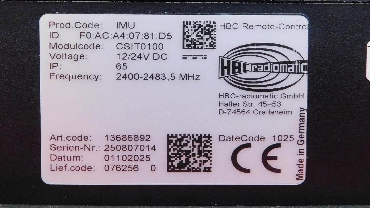
NO9IMU
Aug 04, 2026Inertial Measurement Unit
Equipment Class
DSS - Part 15 Spread Spectrum Transmitter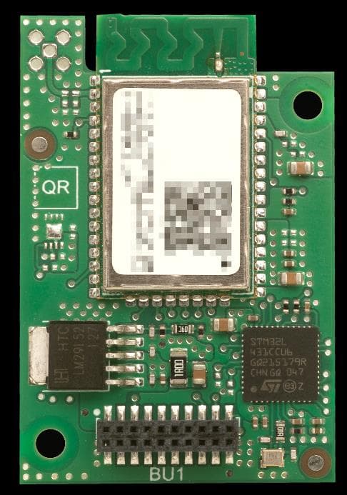
NO9TC190
Jul 26, 2023DECT ULE Radio Module
Equipment Class
PUB - Part 15 Unlicensed PCS Base Station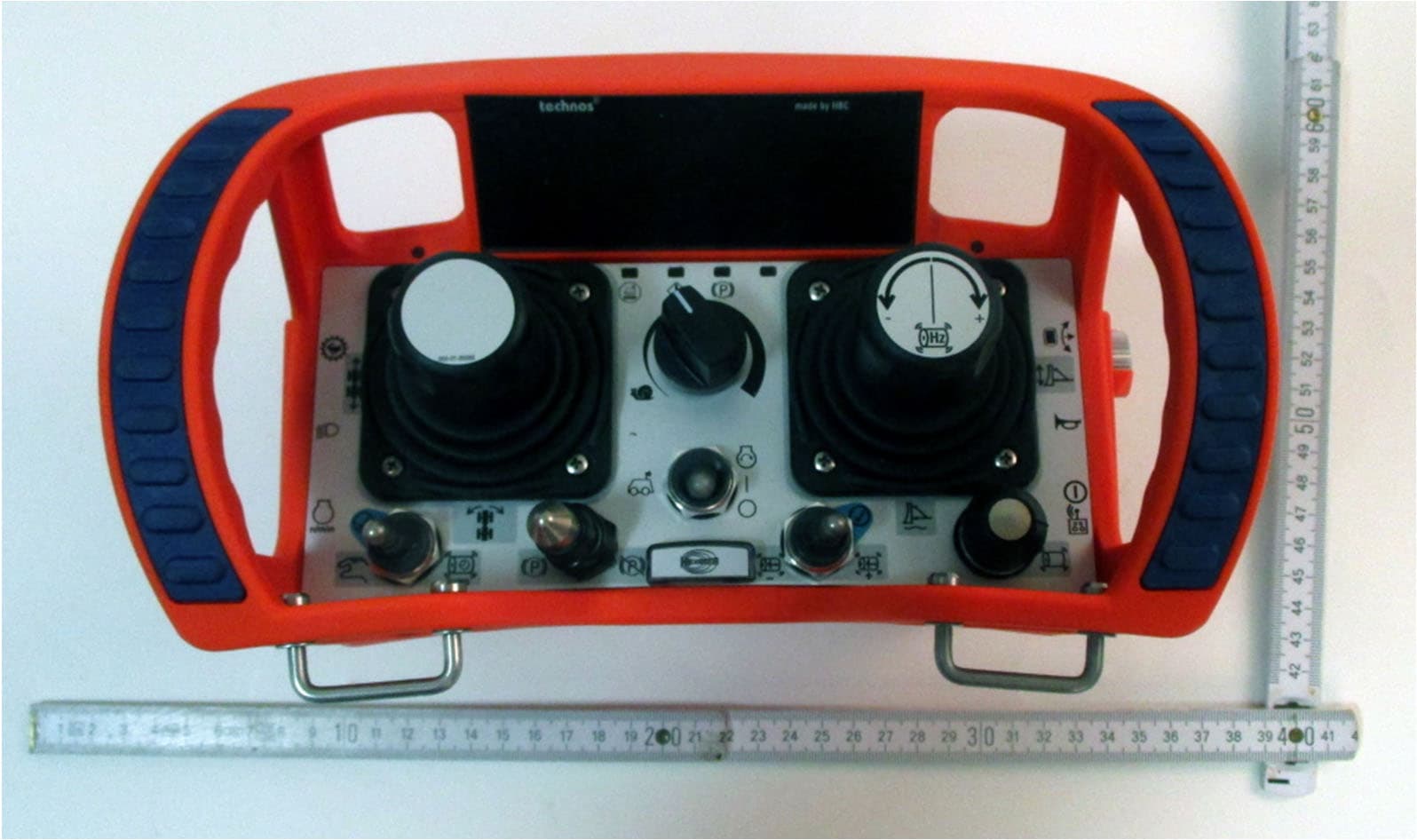
NO9TECA01
Sep 28, 2022Remote Control technos A
Equipment Class
JAD - Part 15 Class A Digital Device
NO9TC792-1
Jan 27, 2021RF Module 902-928 MHz frequency hopping
Equipment Class
DTS - Digital Transmission System
NO9TC240
Jul 01, 2012Bluetooth Module
Equipment Class
DSS - Part 15 Spread Spectrum Transmitter