NO9MICRON7Remote control with RFID
HBC-radiomatic GmbH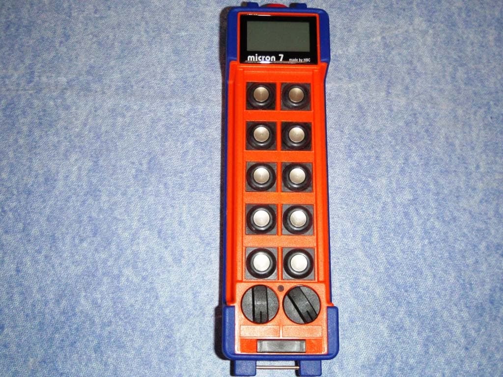
Click to zoom
Application Details
- Equipment Class
- DXX - Part 15 Low Power Communication Device Transmitter
- Date of Grant
- Jul 24, 2011
- Application Purpose
- Original Equipment
- Date of Application
- Jul 24, 2011
- Equipment Note
- Remote control with RFID
- Frequency Range
- 13.56000000 - 13.56000000
- Company
- HBC-radiomatic GmbH
- Country
- Germany
Documents & Files
Document Text
Text extracted from the exhibit documents filed with the FCC. Open a document above to read the original.
Users Manual
micron 7 AOM70U00 Operating Instructions Original Operating Instructions Table of Contents Safety Instructions Intended Use Safety Instructions for Installation and Operation FCC notes IC notes Operation Activating the Transmitter Deactivating the Transmitter Automatic Switch-OFF (APO Function) Display Status Display Individual display settings Battery and Battery Charger Charging the battery Options Safety Features Frequency Management Catch-Release Tandem Operation Catch-Release-Tandem Operation Cable Control radiomatic ® masterkey Address Changeover via Coding Plug Utilization of Button as Shift Key Enabling of the Proportional Outputs Rotary Switch for Preselected Speed Slewing Gear Release Feedback by LED RF-amplifier Pre-selection of Trolley or Hoist Transmitter Key up Technical Data Dimensions Troubleshooting Maintenance Attachments: Return delivery note, system specific views, circuit diagrams and /or output wiring Pictographs Danger due to electrical voltage. Touching live parts inside the unit can be fatal or cause serious injuries. Instructions for occupational health and safety. Not following these instructions can cause accidents, which can cause damage, serious injuries or even death. Important information about the operation of the radio system Manufacturer: HBC-radiomatic GmbH • Haller Straße 45 – 53 • 74564 Crailsheim • Germany • Tel. +49 7951 393-0 • [email protected]. HBC.radiomatic GmbH is not liable for any misprints or errors! – Specifications and design subject to change without notice. ® radiomatic and radiobus are registered German trademarks. © 07 / 2011, HBC-radiomatic GmbH, 74564 Crailsheim, Germany No part of this document may be reproduced in any manner whatsoever without the expressed written permission of HBC-radiomatic GmbH. Safety Instructions Read through these operating instructions carefully before working with the radio system. This applies in particular to the installation, commissioning and maintenance of the radio system. The operating instructions are a constituent part of the radio control system and must always be kept close at hand for the responsible personnel. The term ‘machine’ is used in the operating instructions for the different possible uses of the radio system. Intended Use The radio system serves to control machines and for data transfer. Observe the job safety and accident prevention regulations applicable to each application. The intended use also includes reading the operating instructions and adhering to all safety information contained therein. The radio system must not be used in areas where there is a risk of explosion, nor for the control of machines used to convey persons, unless it is explicitly approved by the manufacturer for these uses. Modifications to the radio system may only be carried out by specialist personnel who have been trained and authorized by HBC-radiomatic. All modifications must be documented at the factory in the radio control master file. The radio control system safety devices must not be modified, removed or bypassed. In particular, modifications to any part of the radio system's complete emergency-stop system are impermissible. Safety Instructions for Installation and Operation The electrical connection per the accompanying output wiring diagram must be established by a qualified electrician exclusively. The receiver may only be opened by trained personnel. Components inside the receiver can be energized at life-threatening voltages. The supply voltage for the machine must be deactivated before the receiver is opened. Please also note with radio systems, that the presence of persons in the danger zone - in particular beneath the load (cranes!) - is prohibited in every instance. Select a safe location for radio control, from which you have a good and complete view of the working movements of the machine, the load movements and the surrounding working conditions. It is not permissible to put a radio transmitter unattended to one side whilst activated. Always switch the radio transmitter off when it is not required. This applies in particular if you change location, when working without radio control, during breaks and at the end of work. Always safeguard the radio transmitter against use by unauthorized persons, for example by locking it away. In the event of an emergency and with all faults, switch the radio transmitter off immediately by pressing the STOP switch. Only operate the radio system when it is in perfect working order. Faults and defects that could influence safety must be rectified before the system is put back into operation, by specialists who have been trained and authorized by HBC-radiomatic. Note that the operational directions of the operating elements may appear inverted depending on location and viewing angle to the machine. This applies in particular to rotary cranes, if your location changes from inside to outside the radius of the crane. The operator must make himself familiar with the directional markings on the machine before the start of work. Repairs may only be carried out by specialist personnel who have been trained and authorized by HBC-radiomatic. Use original replacement parts and accessories (e.g. rechargeable batteries) exclusively; otherwise it is possible that the equipment safety can no longer be guaranteed and our extended warranty will be voided. Remain vigilant when working with the radio system and familiarize yourself with its functions. This applies in particular if you are working with it for the first time or if you work with it only occasionally. Check each time before starting work the function of the STOP switch. When you press the STOP switch with the transmitter on, the status LED and the display of the transmitter have to go out. If the status LED and the display don’t go out then you have to disable the radio control system immediately. Remove the battery and the radiomatic ® iLOG from the transmitter and inform a s…
Text truncated - open the document above for the full version.
External Photos
Test report no.: 1-3057-01-03/10 2011-07-20 Page 20 of 26 Annex B External photographs of the EUT Photo documentation: Photo 1: Photo 2: Test report no.: 1-3057-01-03/10 2011-07-20 Page 21 of 26 Photo 3:
ID Label/Location Info
W eitergabe sowie V ervielfältigung dieser Unterlage, V erwertung und Mitteilung ihres In- halts sind nicht gestattet, soweit nicht ausdrücklich zugestanden. Zuwiderhandlungen verpflichten zu Schadensersatz. Alle Rechte für den F all der P atentierung oder GM-Ein- tragung vorbehalten. Copying of this document, and giving it to others and the use or communication of the contents thereof , are forbidden without express authority . Offenders are liable to the payment of damages. All rights are reserved in the event of the grant of patent or the registration of a utility model or design. H B C - r a d i o m a t i c G M B H D a t u m : D a t e : Z . - N r. : D o c . - N o . : G e z e i c h n e t / D r a w n b y : G e p r ü f t / C h e c k e d : D a t e i : B l a t t : F i l e : S h e e t : HBC-radiomatic GmbH Postfach 1561 D-74555 Crailsheim Typenschild im Batteriefach nameplate inside battery compartment Sender micron 7 Ansicht von unten transmitter micron 7 bottom view Position Typenschild micron 7 Location nameplate micron 7 B.Bülow B.Bülow Ans_mic7_typ.cdr 1/1 11.05.2011 AA.472.A.91 W eitergabe sowie V ervielfältigung dieser Unterlage, V erwertung und Mitteilung ihres In- halts sind nicht gestattet, soweit nicht ausdrücklich zugestanden. Zuwiderhandlungen verpflichten zu Schadensersatz. Alle Rechte für den F all der P atentierung oder GM-Ein- tragung vorbehalten. Copying of this document, and giving it to others and the use or communication of the contents thereof , are forbidden without express authority . Offenders are liable to the payment of damages. All rights are reserved in the event of the grant of patent or the registration of a utility model or design. H B C - r a d i o m a t i c G M B H D a t u m : 11 . 0 5 . 2 0 11 Ty p _ m i c 7 _ f c c 1 . c d r B . B ü l o w A A . 4 7 1 . A . 9 3 1 / 1 D a t e : Z . - N r. : D o c . - N o . : G e z e i c h n e t / D r a w n b y : B . B ü l o w Ty p e n s c h i l d m i c r o n 7 - F C C n a m e p l a t e m i c r o n 7 - F C C G e p r ü f t / C h e c k e d : D a t e i : B l a t t : F i l e : S h e e t : HBC-radiomatic GmbH Postfach 1561 D-74555 Crailsheim HBC-radiomatic GmbH Tel.: +49(0)7951/393-0 Made in Germany Product Code: micron 7 Transmitter Ser.No.: ???-???????? IP 65 / Nema 4Voltage: 3,6V DC Frequency (MHz): 902,000 - 917,975 FCC ID: N09MICRON7 CANADA : 2977A-MICRON7 This device complies with part 15 of the FCC Rules. Operation is subject to the following two conditions: (1) This device may not cause harmful interference, & (2) This device must accept any interference received, including interference that may cause undesired operation.
Internal Photos
Test report no.: 1-3057-01-03/10 2011-07-20 Page 22 of 26 Annex C Internal photographs of the EUT Photo documentation: Photo 1: Photo 2: Test report no.: 1-3057-01-03/10 2011-07-20 Page 23 of 26 Photo 3: Photo 4: Test report no.: 1-3057-01-03/10 2011-07-20 Page 24 of 26 Photo 5: Photo 6: Test report no.: 1-3057-01-03/10 2011-07-20 Page 25 of 26 Photo 7: Photo 8:
Test Report
2011-07-20 Page 1 of 26 TEST REPORT Test Report No.: 1-3057-01-03/10 Testing Laboratory Applicant CETECOM ICT Services GmbH Untertürkheimer Straße 6 – 10 66117 Saarbrücken/Germany Phone: + 49 681 5 98 - 0 Fax: + 49 681 5 98 - 9075 Internet: http://www.cetecom.com e-mail: [email protected] Accredited Test Laboratory: The test laboratory (area of testing) is accredited according to DIN EN ISO/IEC 17025 DAkkS registration number: D-PL-12076-01-01 Area of Testing: Radio Satellite Communications HBC radiomatic GmbH Haller Str. 45-53 74564 Crailsheim /Germany Phone: +49 (0) 7951 393 0 Fax: +49 (0) 7951 393 723 Contact: D. Hahn e-mail: [email protected] Phone: +49 (0) 7951 393 725 Manufacturer HBC radiomatic GmbH Haller Str. 45-53 74564 Crailsheim /Germany Test Standard/s 47 CFR Part 15 Title 47 of the Code of Federal Regulations; Chapter I-Federal Communications Commission subchapter A - general, Part 15-Radio frequency devices RSS - 210 Issue 8 Spectrum Management and Telecommunications - Radio Standards Specification Low-power Licence-exempt Radiocommunication Devices (All Frequency Bands): Category I Equipment For further applied test standards please refer to section 3 of this test report. Test Item Kind of test item: HBC remote control Model name: micron7 FCC ID: NO9MICRON7 IC: 2977A-HBCM7 Frequency [MHz]: 13.56 MHz Power supply: 3.6 V DC from BA223030 Ni-MH battery Temperature range: -20 °C to +70 °C This test report is electronically signed and valid without handwriting signature. For verification of the electronical signatures, the public keys can be requested at the testing laboratory. Test performed: Test Report authorised: Michael Berg Jakob Reschke Test report no.: 1-3057-01-03/10 2011-07-20 Page 2 of 26 1 Table of contents 1 Table of contents ............................................................................................................................................ 2 2 General information ....................................................................................................................................... 3 2.1 Notes ..................................................................................................................................................... 3 2.2 Application details ............................................................................................................................... 3 3 Test standard/s ............................................................................................................................................... 3 4 Test environment ............................................................................................................................................ 3 5 Test item .......................................................................................................................................................... 4 6 Test laboratories sub-contracted ................................................................................................................. 4 7 Summary of measurement results ............................................................................................................... 5 8 RF measurement testing ............................................................................................................................... 6 8.1 Description of test setup .................................................................................................................... 6 8.1.1 Radiated measurements............................................................................................................. 6 8.1.2 Conducted measurements.......................................................................................................... 7 8.2 Additional comments .......................................................................................................................... 7 8.3 RSP100 Test report cover sheet / Performance test data ............................................................... 8 9 Measurement results ...................................................................................................................................... 9 9.1 Timing of the transmitter .................................................................................................................... 9 9.2 Field strength of the fundamental ................................................................................................... 11 9.3 Occupied bandwidth ......................................................................................................................... 12 9.4 Field strength of the harmonics and spurious ............................................................................... 13 10 Test equipment and ancillaries used for tests ................................................................................... 17 Annex A Photographs of the test set-up ..................................................................................................... 19 Annex B External photographs of the EUT ................................................................................................. 20 Annex C Internal photographs of the EUT .................................................................................................. 22 Annex D Document history .......................................................................................................................... 26 Annex E Further information ........................................................................................................................ 26 Test report no.: 1-3057-01-03/10 2011-07-20 Page 3 of 26 2 General information 2.1 Notes The test results of this test report relate exclusively to the test item specified in this test report. CETECOM ICT Services GmbH does not assume responsibility for any conclusions and generalisations drawn from the test results with regard to other specimens or sample…
Text truncated - open the document above for the full version.
Test Setup Photos
Test report no.: 1-3057-01-03/10 2011-07-20 Page 19 of 26 Annex A Photographs of the test set-up Photo documentation: Photo 1: Photo 2:
Contact Information
Applicant
Jeff Allan(CEO of US Entity)
Test Firm
cetecom advanced GmbHGerald Schmidt
Technical Specifications
| # | Rule Parts | Frequency Range | Power Output |
|---|---|---|---|
| 1 | 15C | 13.56 MHz - 13.56 MHz | - |
Other Applications from HBC-radiomatic GmbH
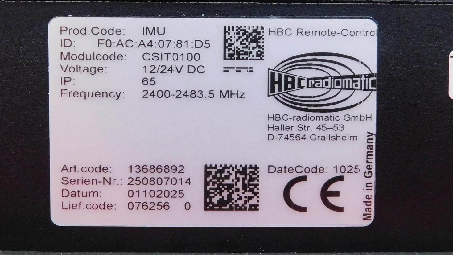
NO9IMU
Aug 04, 2026Inertial Measurement Unit
Equipment Class
DSS - Part 15 Spread Spectrum Transmitter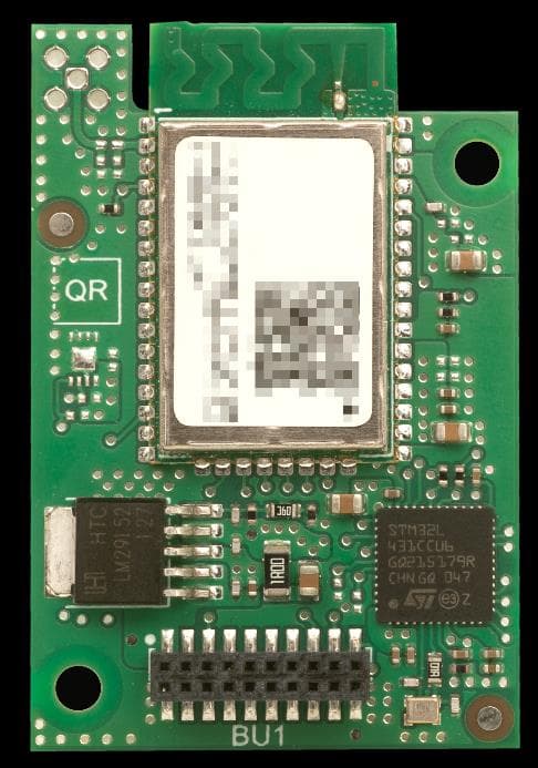
NO9TC190
Jul 26, 2023DECT ULE Radio Module
Equipment Class
PUB - Part 15 Unlicensed PCS Base Station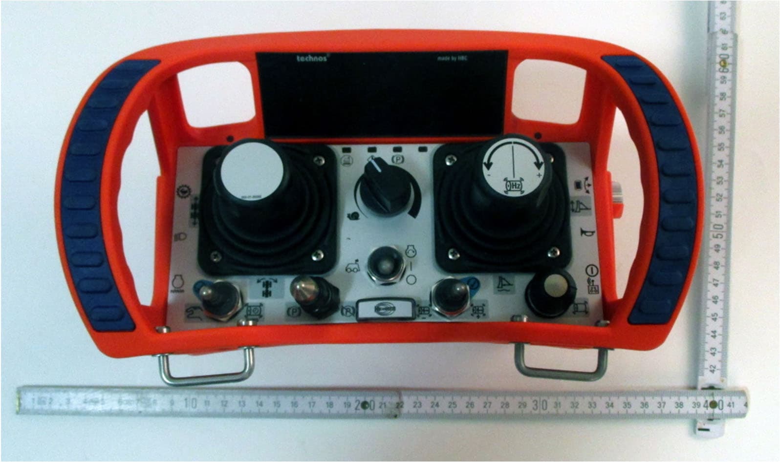
NO9TECA01
Sep 28, 2022Remote Control technos A
Equipment Class
JAD - Part 15 Class A Digital Device
NO9TC792-1
Jan 27, 2021RF Module 902-928 MHz frequency hopping
Equipment Class
DTS - Digital Transmission System
NO9TC240
Jul 01, 2012Bluetooth Module
Equipment Class
DSS - Part 15 Spread Spectrum Transmitter