NORTM60Crane controller
Angel Iglesias SA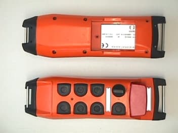
Click to zoom
Application Details
- Equipment Class
- TNT - Licensed Non-Broadcast Transmitter Worn on Body
- Date of Grant
- Sep 19, 2001
- Application Purpose
- Original Equipment
- Date of Application
- Sep 18, 2001
- Equipment Note
- Crane controller
- Frequency Range
- 450.00000000 - 470.00000000
- Company
- Angel Iglesias SA
- Country
- Spain
Documents & Files
Document Text
Text extracted from the exhibit documents filed with the FCC. Open a document above to read the original.
Users Manual
TM60Pi (06/00) IKUSI reserves the right to modify this information without prior notification. USER'S MANUAL TM60 CONSOLE TRANSMITTER TM60Pi (06/00)PAG. i I N D E X Pg. 1.- DESCRIPTION ........................................................................................................1 2.- SAFETY PRECAUTIONS........................................................................................2 2.1.- What you must do..........................................................................................2 2.2.- What you must not do....................................................................................2 3.- INSTALLATION .......................................................................................................3 3.1.- CB60 Battery charger ....................................................................................3 3.2.- Receiver ........................................................................................................4 3.3.- Starting up .....................................................................................................7 3.4.- Spurious ........................................................................................................9 4.- USING THE SET .....................................................................................................10 5.- MAINTENANCE ......................................................................................................11 5.1.- Guarantee......................................................................................................11 5.2.- Precautions....................................................................................................11 5.3.- Preventive maintenance ................................................................................12 5.4.- Identifying faults.............................................................................................13 5.5.- Spare parts ....................................................................................................14 TM60Pi (06/00)PAG. 1 1.- DESCRIPTION The TM60/3, TM60/4, TM60/5, TM60/6, TM60/7, and TM60/8 console type transmitter radio remote control systems, are designed for the remote control of hoists and cranes (overhead cranes, tower cranes, hydraulic loader cranes, concrete pumps, driverless vehicles, etc) and are particularly suitable for applications when the operator needs to be able to choose the best location from which to carry out an operation. The system consists of a transmitter for selecting commands and a receiver which is connected to the electrical system of the machine to be operated. The system also comes with a battery charger and two rechargeable batteries. The main specifications are as follows: The TM60 Frequency band405 a 475 MHz Response Time100 ms Temperature range-20º a +65ºC The TM60/3, TM60/4, TM60/5, TM60/6, TM60/7, and TM60/8 transmitters Transmission power10 mW ProtectionIP65 The R60/9, R60/18, R60/26 and R60/38 receivers Power supply48, 115, 230 Vac ± 10%, 50/60 Hz Optional 12 or 24 Vdc Consumption30 to 40 W, depending on models Relays230 Vac/8 A ProtectionIP55 The CB60 battery charger Power supply230 Vac ± 10%, 50 Hz; optional 115 Vac, 60 Hz or 24 Vdc The BT12 batteries Voltage7,2 V Capacity 1200 mAh Charging temperature5º a 35ºC Autonomy8 to 12 h, depending on models TM60Pi (06/00)PAG. 2 2.- SAFETY PRECAUTIONS These instructions must be read carefully in order to install and use the set properly and to keep it in perfect working condition and to reduce the risks of misuse. Do not use this set on machines for the lifting of persons or in potentially explosive atmospheres. Any use other than that specified in this manual is dangerous. The following instructions must be strictly adhered to. 2.1.- What you must do: ! Strictly adhere to the instructions for installation contained in this manual. ! Make sure that the installation is carried out by professional and competent personnel. ! Ensure that all site and prevailing safety regulations are fully respected. ! Make sure that this manual is permanently available to the operator and maintenance personnel. ! Keep the transmitter out of reach of unauthorised personnel. ! Remove the transmission key when the set is not in use. ! On starting each working day, check to make sure that the STOP button and other safety measures are working. ! When in doubt, press the STOP button. ! Whenever several sets have been installed, make sure the transmitter you are going to use is the right one. Identify the machine controlled on the label for this purpose on the transmitter. ! Service the equipment periodically. ! When carrying out repairs, only use spare parts supplied by IKUSI dealers. 2.2.- What you must not do: ! Never make any changes to the set, which have not been studied and approved by the manufacturer. ! Never power the equipment other than with the specified power supply. ! Never allow unqualified personnel to operate the equipment. ! After use, never leave the equipment ON. Always use the contact key or the STOP button to avoid accidentally activating manoeuvres. ! Do not use the set when visibility is limited. ! Avoid knocking or dropping the set. ! Do not use the set if failure is detected. TM60Pi (06/00)PAG. 3 3.- INSTALLATION 3.1 The CB60 battery charger Connect the charger to the mains using the power source and cable supplied. On installing the battery charger, bear in mind that the batteries must be charged at temperatures over 5ºC and that the power supply must be left on all night. Also remember that the charger must not be left in direct sunlight as the batteries will not become fully charged at temperatures exceeding 35ºC. Place the batteries in the charger. The LEDs should light up, indicating that recharging is in process. Complete recharging takes 12 hours, but the batteries may remain in the charger for an unlimited period of time. The capacity of the batteries decreases with use. T…
Text truncated - open the document above for the full version.
Users Manual
TM60Bi (08/00) IKUSI reserves the right to modify this information without prior notification. USER'S MANUAL TM60 PUSH-BUTTON TRANSMITTER TM60Bi (08/00)PAG. i I N D E X Pg. 1.- DESCRIPTION ........................................................................................................1 2.- SAFETY PRECAUTIONS........................................................................................2 2.1.- What you must do..........................................................................................2 2.2.- What you must not do....................................................................................2 3.- INSTALLATION .......................................................................................................3 3.1.- CB60 Battery charger ....................................................................................3 3.2.- Receiver ........................................................................................................4 3.3.- Starting up .....................................................................................................7 3.4.- Spurious ........................................................................................................9 4.- USING THE SET .....................................................................................................10 5.- MAINTENANCE ......................................................................................................11 5.1.- Guarantee......................................................................................................11 5.2.- Precautions....................................................................................................11 5.3.- Preventive maintenance ................................................................................12 5.4.- Identifying faults.............................................................................................13 5.5.- Spare parts ....................................................................................................14 TM60Bi (08/00)PAG. 1 1.- DESCRIPTION The TM60/1 and TM60/2 push-button transmitter type, radio remote control systems are designed for the remote control of hoists and cranes, and are particularly suitable for applications when the operator needs to be able to choose the best location from which to carry out an operation. The system consists of a transmitter for selecting commands and a receiver which is connected to the electrical system of the machine to be operated. The system also comes with a battery charger and two rechargeable batteries. The main specifications are as follows: The TM60 Frequency band405 a 475 MHz Response Time 100 ms Temperature range-20º a +65ºC The T60/1 and T60/2 transmitters Transmission power10 mW ProtectionIP65 The R60/9 and R60/18 receivers Power supply48, 115, 230 Vac ± 10%, 50/60 Hz Optional 12 or 24 Vdc Consumption30 W Relays230 Vac/8 A ProtectionIP55 The CB60 battery charger Power supply230 Vac ± 10%, 50Hz; optional 115 Vac, 60 Hz or 24 Vdc The BT06 batteries Voltage7,2 V Capacity 600 mAh Charging temperature5º a 35ºC Autonomy6 h TM60Bi (08/00)PAG. 2 2.- SAFETY PRECAUTIONS These instructions must be read carefully in order to install and use the set properly and to keep it in perfect working condition and to reduce the risks of misuse. Do not use this set on machines for the lifting of persons or in potentially explosive atmospheres. Any use other than that specified in this manual is dangerous. The following instructions must be strictly adhered to. 2.1.- What you must do: ! Strictly adhere to the instructions for installation contained in this manual ! Make sure that the installation is carried out by professional and competent personnel. ! Ensure that all site and prevailing safety regulations are fully respected. ! Make sure that this manual is permanently available to the operator and maintenance personnel. ! Keep the transmitter out of reach of unauthorised personnel. ! Remove the transmission key when the set is not in use. ! On starting each working day, check to make sure that the STOP button and other safety measures are working. ! When in doubt, press the STOP button. ! Whenever several sets have been installed, make sure the transmitter you are going to use is the right one. Identify the machine controlled on the label for this purpose on the transmitter. ! Service the equipment periodically. ! When carrying out repairs, only use spare parts supplied by IKUSI dealers. 2.2.- What you must not do: ! Never make any changes to the set, which have not been studied and approved by the manufacturer. ! Never power the equipment other than with the specified power supply. ! Never allow unqualified personnel to operate the equipment. ! After use, never leave the equipment ON. Always use the contact key or the STOP button to avoid accidentally activating manoeuvres. ! Do not use the set when visibility is limited. ! Avoid knocking or dropping the set. ! Do not use the set if failure is detected. TM60Bi (08/00)PAG. 3 3.- INSTALLATION 3.1.- The CB60 battery charger Connect the charger to the mains using the power source and cable supplied. On installing the battery charger, bear in mind that the batteries must be charged at temperatures over 5ºC and that the power supply must be left on all night. Also remember that the charger must not be left in direct sunlight as the batteries will not become fully charged at temperatures exceeding 35ºC. Place the batteries in the charger. The LEDs should light up, indicating that recharging is in process. Complete recharging takes 12 hours, but the batteries may remain in the charger for an unlimited period of time. The capacity of the batteries decreases with use. Their life span is estimated to be 500 recharging cycles, but this depends largely on the conditions of use, for which the following is recommended: ! Do not recharge the battery until it is completely flat. The transmitter indic…
Text truncated - open the document above for the full version.
Block Diagram
2.2.- BRIEF DESCRIPTION AND DESTINATION (USE) OF UNIT. The TM60 remote control system has been designed to operate remotely by radio, electrical or electrohydraulic machinery operated with relays, frequency inverters or valves. The most common application for it, is the remote control of lifting machines such overhead cranes, tower cranes, loader cranes or concrete pumps, as well as driverless vehicles. The set consists on a portable battery powered transmitter which is controlled by the operator, and a receiver which is installed in the machine which is going to be operated. The set is supplied with a battery charger and two rechargeable batteries. There is a great variety of machinery and therefore, the configuration of the set is variable, particularly in the case of transmitter. The basic configurations have been described above. 2.3.- POSSIBLE VARIATIONS. When a fixed transmitter is requested, instead of a portable unit, then, the transmitter is introduced in a box with external power supply. In such cases, models are named: TM60/F.9 – systems with 9 output relays TM60/F.18 – systems with 18 output relays 3.- RADIO TRANSMITTER TD450 3.1.- GENERAL FUNCTIONAL DESCRIPTION. The Radio Transmitter module TD450 converts the analogue signal given by the GMSK modem of the transmitter logic unit, into a FM modulated radio signal. Features: • 450-470 MHz frequency band. • Frequency selected through a serial data input, with 25 KHz steps. • Synthesised frequency through a PLL phase loop. • Double modulation. Radio Transmitter TD450 consists on a 6 layers printed circuit board, containing following blocks: • Analogue input signal equalizer. • Oscillator – Modulator and Frequency Synthesiser. • Buffer – preamplifier. • Amplifier and filters. 3.1.1.- BLOCK DIAGRAM. VC O PLL Ant Mod O. R. 3.1.2.- ANALOGUE INPUT SIGNAL EQUALIZER. The signal to be modulated is first equalised to a suitable level to obtain a wider band in the receiver. Also, a 5V stabilised voltage is obtained for the supply of the synthesiser and output power stage. 3.1.3.- OSCILLATOR – MODULATOR AND FREQUENCY SYNTHESISER. The oscillator is a VCO controlled by a PLL, working at f OSC = ( f RF /2 ). The VCO frequency is set by the transmitter logic unit through a serial data input, and the reference frequency is obtained by a 6,4 MHz crystal controlled oscillator. The modulation signal is introduced simultaneously in both, the VCO, which modulates the higher part of the input spectrum, and the reference oscillator, which modulates the lower part. The level of the low frequency data signal supplied by the transmitter logic unit, is set through the R7 potentiometer, thus adjusting the emission bandwidth. The synthesizer features a VCO composed by transistor Q4 and its associates components, plus a PLL circuit composed by integrated circuits U6 (counter and phase comparator), U4 (preescaler) and U5 low pass filter. The reference oscillator circuit, is composed by transistor Q6 and its associates components. A temperature compensated frequency network featuring a NTC R1, keep the frequency independent form temperature changes. The error voltage (control voltage over VCO) varies D1’s capacitance then moving the central frequency of VCO. The higher frequency part of modulation signal varies D2’s capacitance while the lower part varies D4’s capacitance. The PLL circuit consists in a 6,4 MHz reference oscillator, which give the 6,25 KHz reference frequency, a phase comparator, the prescaler divisor and a circuit which gives a signal when the PLL is locked, thus allowing to supply power to the RF amplification stage. 3.1.4.- BUFFER–PREAMPLIFIER. This stage separates the VCO and the RF amplifier, thus reducing the influence of load variations produced by level changes in the transmitter output stage. The amplification at this stage is non linear, producing harmonics at two times its input frequency, thus giving the output frequency f RF . A high pass filter eliminates harmonics produced under frequency f RF . 3.1.5.- AMPLIFIER AND FILTERS This two stage amplifier gives the RF output power. Then the signal is filtered through a low pass elliptic filter to eliminate the resulting components higher in frequencies than f RF . When the EMIS emission control signal is off, power supply to all RF parts of the circuit is switched off, and the transmitter remains on Stand-by mode.
Cover Letter(s)
confidentiallity letter.bmp (748x1053x24b bmp)
Cover Letter(s)
-----Original Message----- From: Barry C. Quinlan [mailto:[email protected]] Sent: Wednesday, August 29, 2001 7:49 AM To: [email protected]; Desiree Patterson Subject: NORTM60 Dear Andrew and Desiree, 1. We have a few issues to address on this one. 2. The letter requesting confidentiality is too broad. The FCC will only grant confidentiality on the schematics, block diagram, bills of material and operational description. All other documentation will be public. Please resubmit a new letter requesting confidentiality for these parts only and justify the request based on proprietary or competitive issues in the letter. Attached 3. Please reconfirm your power measurement data calculations. The product specification says 10mW. The previous unit FCC ID:NORT-50 had a power level of 3.25mW. You are reporting 0.10mW on page 11 of your test report. Please confirm that this is correct. The output power of the last unit may have been tested using a direct connection to the antenna port. On this unit that was not possible, so Andrew made a field strength measurement at 3 m and calculated the ERP relative to a half-wave dipole. The numbers you refer to were indeed measured. Revised test report pages supplied. 4. We need a signed certification agreement with the applicant. Please send us a signed certification agreement. This should have been sent to you directly by Ikusi. However I am in the process of verifying that. - Supplied 5. The manual does not address RF exposure issues. Please add the statement: “Important note: To comply with FCC RF exposure compliance requirements, this device and its antenna must not be co-located or operating in conjunction with any other antenna or transmitter.” Attached please find revision made to page 2 of the manual. 6. Please submit a photograph or drawing of the label information. Please be sure to follow 2.925 and include the item “FCC ID NORTM60” on a single line. Attached is a picture of the label they use 7. Per 2.1033 (c) (8) and (9), please provide a tune up procedure exhibit and an exhibit showing the dc voltages and currents into the final stage of the amplifier. We are still trying to get this - supplied Thank you, Dana Hensyel ------------------------------------------------------------------------------- Curtis-Straus LLC Voice: 978.486.8880 x270 527 Great Road Fax: 978.486.8828 Littleton, MA 01460 http://www.curtis-straus.com --------------------------------------------------------------------------------
External Photos
2.5.- PHOTOGRAPHS 2.5.1.- PUSHBUTTONS TRANSMITTERS TRANSMITTER T60/1 TRANSMITTER T60/2 2.5.2.- JOYSTICKS TRANSMITTERS TRANSMITTER T60/3 TRANSMETTITORE T60/4 TRANSMITTER T60/5 TRANSMITTER T60/6 TRANSMITTER T60/7 TRANSMITTER T60/8
ID Label/Location Info
labels.bmp (1122x1580x24b bmp)
Internal Photos
3.5.- PHOTOGRAPHS.
Operational Description
2.2.- BRIEF DESCRIPTION AND DESTINATION (USE) OF UNIT. The TM60 remote control system has been designed to operate remotely by radio, electrical or electrohydraulic machinery operated with relays, frequency inverters or valves. The most common application for it, is the remote control of lifting machines such overhead cranes, tower cranes, loader cranes or concrete pumps, as well as driverless vehicles. The set consists on a portable battery powered transmitter which is controlled by the operator, and a receiver which is installed in the machine which is going to be operated. The set is supplied with a battery charger and two rechargeable batteries. There is a great variety of machinery and therefore, the configuration of the set is variable, particularly in the case of transmitter. The basic configurations have been described above. 2.3.- POSSIBLE VARIATIONS. When a fixed transmitter is requested, instead of a portable unit, then, the transmitter is introduced in a box with external power supply. In such cases, models are named: TM60/F.9 – systems with 9 output relays TM60/F.18 – systems with 18 output relays
Parts List/Tune Up Info
RF TRANSMITTER TD450 C39 TP8 C85 R7 - Supply: 7,2V at F3.- Output frequency is pr ogrammed into the logic. - Tune up f out , using trimmer C85, until the frequ ency of the carrier equals to f out ± 2 KHz. (frequency-meter)- Measure tracking voltage of PLL (TP8 to GND), tune it using trimmer C39, until voltage equals to 3.25 V ± 0.25V.- Tune up the deviation of the modulation, with the potentiometer R7, until deviation equals to 3.6 KHz (measured using a modulation- meter (RACAL DANA 9009 A)) Tracking Voltage at PLL and frequency Tracking V at PLL 3.25 V Tracking V at PLL. Tuning up in frequency Quatz at 6,4 Mhz Deviation Modulation 3,6 khz F3 RF TRANSMITTER TD450 C64 C62 - Tune up the operating power out, using trimmers C61, C 62, C64 and C63,(follow the ordered list) to maximise P out. , measured with a spectrum analyser. - Always must be: P out (PRA) < 10 dBm. C63 C61 R19 Tuning of operating power level Tuning power Antenna
Test Report
Acme Testing Co. 2002 Valley Highway PO Box 3 Acme WA 98220-0003 phone:888 226-3837 fax: 360 595-2722 Document Number: 2001128 Document Date: 15 July 2001 Angel Iglesias S.A., Model TM60/1.9 FCC Part 90 Report of Measurements FCC ID: NORTM60 Page 1 of 27 FCC PART 90 REPORT OF MEASUREMENTS DEVICE: 450 MHz – 470 MHz 1 CHANNEL TRANSMITTER MODEL: TM60/1.9 MANUFACTURER: ANGEL IGLESIAS S.A. ADDRESS: POL. IND. 27 n°30 (MARTUTENE) 20014 SAN SEBASTIAN SPAIN WORK ORDER: 2465HR Acme Testing Co. 2002 Valley Highway PO Box 3 Acme WA 98220-0003 phone:888 226-3837 fax: 360 595-2722 Document Number: 2001128 Document Date: 15 July 2001 Angel Iglesias S.A., Model TM60/1.9 FCC Part 90 Report of Measurements FCC ID: NORTM60 Page 2 of 27 1. GENERAL .......................................................................................................................................................................4 1.1 DOCUMENT HISTORY..............................................................................................................................................4 1.2 PURPOSE.................................................................................................................................................................4 1.3 MANUFACTURER.....................................................................................................................................................5 1.4 TEST LOCATION.......................................................................................................................................................5 1.5 ACCREDITATIONS AND LISTINGS............................................................................................................................5 2. TEST RESULTS SUMMARY .......................................................................................................................................6 3. DESCRIPTION OF EQUIPMENT AND PERIPHERALS ........................................................................................7 3.1 EQUIPMENT UNDER TEST (EUT) ............................................................................................................................7 4. EXEMPTION FROM TECHNICAL STANDARDS ...................................................................................................8 5. TEST SET UP PHOTOGRAPHS ..................................................................................................................................9 6. RF POWER OUTPUT ..................................................................................................................................................10 6.1 TEST PROCEDURE.................................................................................................................................................10 6.2 TEST EQUIPMENT..................................................................................................................................................10 6.3 TEST SET-UP BLOCK DIAGRAM.............................................................................................................................11 6.4 MINIMUM STANDARD...........................................................................................................................................11 6.5 TEST RESULTS......................................................................................................................................................11 7. MODULATION LIMITING ........................................................................................................................................12 7.1 TEST PROCEDURE.................................................................................................................................................12 7.2 TEST EQUIPMENT..................................................................................................................................................12 7.3 TEST SET-UP BLOCK DIAGRAM.............................................................................................................................12 7.4 MINIMUM STANDARD...........................................................................................................................................12 7.5 TEST RESULTS......................................................................................................................................................12 8. OCCUPIED BANDWIDTH .........................................................................................................................................13 8.1 TEST PROCEDURES................................................................................................................................................13 8.2 TEST EQUIPMENT..................................................................................................................................................13 8.3 TEST SET-UP BLOCK DIAGRAM.............................................................................................................................13 8.4 MINIMUM STANDARD...........................................................................................................................................13 8.5 TEST RESULTS......................................................................................................................................................13 9. SPURIOUS EMISSION AT ANTENNA TERMINALS............................................................................................15 9.1 TEST PROCEDURES................................................................................................................................................15 9.2 TEST EQUIPMENT..................................................................................................................................................15 9.3 TEST SET-UP BLOCK DIAGRAM..........................................................…
Text truncated - open the document above for the full version.
Test Report
Acme Testing Co. 2002 Valley Highway PO Box 3 Acme WA 98220-0003 phone:888 226-3837 fax: 360 595-2722 Document Number: 2001128 Document Date: 15 July 2001 Angel Iglesias S.A., Model TM60/1.9 FCC Part 90 Report of Measurements FCC ID: NORTM60 Page 4 of 27 1. General 1.1 Document History REVISION DATE COMMENTS - 15 July 2001 Initial Release, Harry H. Hodes A 10 September 2001 Revision made to page 11 to note equation used for RF Power Output Measurement B 19 September 2001 Revision made to page 4 to fix section 1.2- Purpose Note: Acme Testing Co. hereby makes the following statements so as to conform with Chapter 10 (Test Reports) Requirement of ANSI C63.4:1992 “Methods and Measurement of Radio-Noise Emissions from Low-Voltage Electrical and Electronic Equipment in the Range of 9 kHz to 40 GHz”: • The units described in this report were received at Acme Testing Co.’s facilities on 13 April 2001. Testing was performed on the units described in this report on 17 April 2001. • The Test Results reported herein apply only to the Units actually tested, and to substantially identical Units. • This test report must not be used to claim product endorsement by A2LA or any agency of the U.S. Government, or any other foreign government. This document is the property of Acme Testing, Co., and shall not be reproduced, except in full, without prior written approval of Acme Testing Co. However, all ownership rights are hereby returned unconditionally to Angel Iglesias S.A. and approval is hereby granted to Angel Iglesias S.A. and its employees and agents to reproduce all or part of this report for any legitimate business purpose without further reference to Acme Testing Co. 1.2 Purpose The purpose of this report is to show compliance of the 450 MHz – 470 MHz 1 Channel 1 Milliwatt Transmitter, Model TM60/1.9 to the Title 47 CFR: Part 90.201. This report references the applicable electromagnetic requirements. THE DATA CONTAINED IN THIS REPORT WAS COLLECTED AND COMPILED BY: ANDREW K. PACE EMC ENGINEER
Test Report
Acme Testing Co. 2002 Valley Highway PO Box 3 Acme WA 98220-0003 phone:888 226-3837 fax: 360 595-2722 Document Number: 2001128 Document Date: 15 July 2001 Angel Iglesias S.A., Model TM60/1.9 FCC Part 90 Report of Measurements FCC ID: NORTM60 Page 11 of 27 6.3 Test Set-up Block Diagram ANTENNA VARIABLE 1 to 4 SEARCH meters HEIGHT 0.8 m TURNTABLE 3 m TO SPECTRUM ANALYZER 6.4 Minimum Standard Paragraph No. 90.205 (g) contains limits for transmitter of this type. However, this EUT complies with paragraph 90.217, which replaces all of the technical limits set out in part 90 with one power output limit of 120 miliwatts. 6.5 Test Results The measured effective radiated power (ERP) relative to a ha…
Text truncated - open the document above for the full version.
Contact Information
Applicant
M A Portillo
Test Firm
Acme Testing Co.Harry Hodes
Technical Specifications
| # | Rule Parts | Frequency Range | Power Output | Emission | Tolerance |
|---|---|---|---|---|---|
| 1 | 90.217(b) | 450 MHz - 470 MHz | 1.00 mW | 8K25F1D | 2500.0000000000 Hz |
Other Applications from Angel Iglesias SA
NORT-50
Jan 14, 1998Single Channel
Equipment Class
TNT - Licensed Non-Broadcast Transmitter Worn on BodyNORR-50
Nov 25, 1997CXX - Communications Rcvr for use w/ licensed Tx and CBs
Equipment Class
CXX - Communications Rcvr for use w/ licensed Tx and CBs