NOWSPVD-2Vehicle Detector TX
Midian Electronics Inc
Click to zoom
Application Details
- Equipment Class
- TNB - Licensed Non-Broadcast Station Transmitter
- Date of Grant
- Dec 13, 2001
- Application Purpose
- Original Equipment
- Date of Application
- Dec 13, 2001
- Equipment Note
- Vehicle Detector TX
- Frequency Range
- 47.02000000 - 47.40000000
- Company
- Midian Electronics Inc
- Country
- United States
Documents & Files

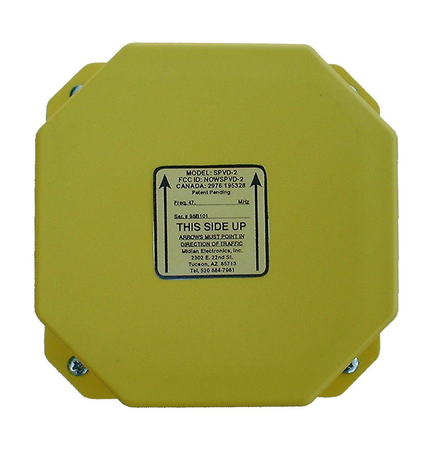

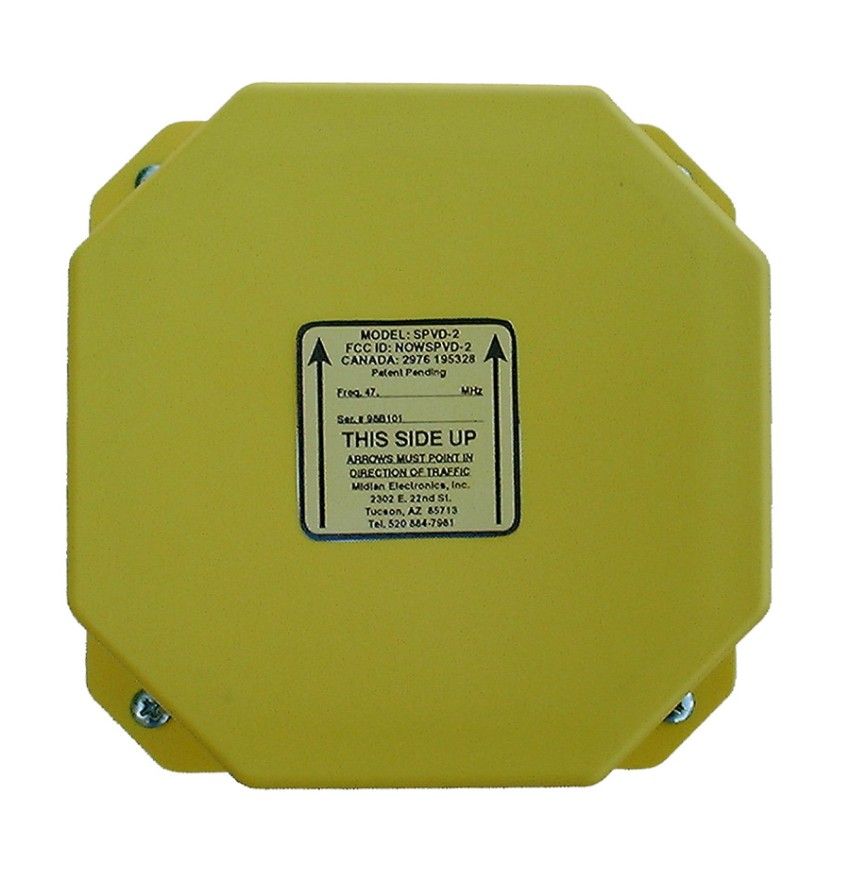
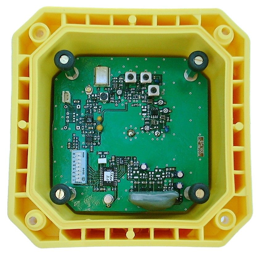
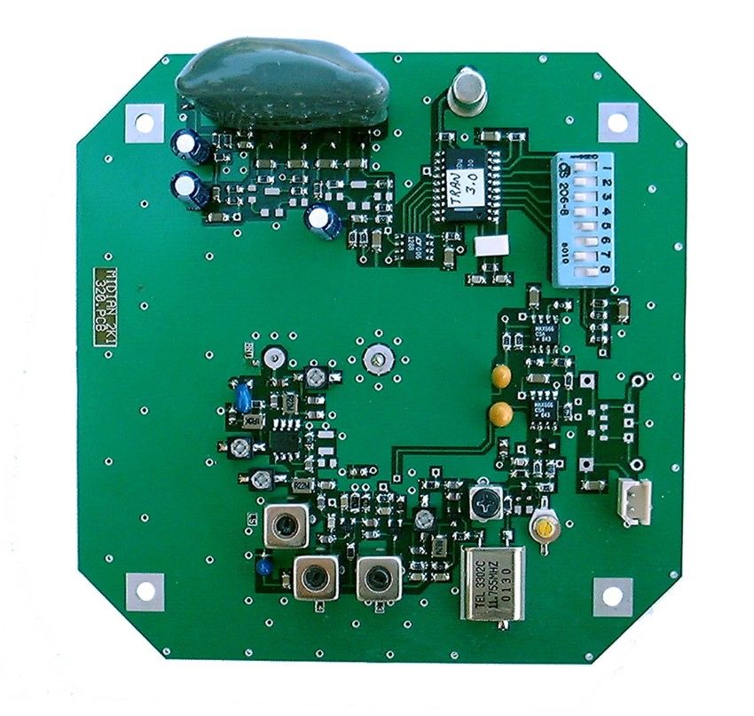
Document Text
Text extracted from the exhibit documents filed with the FCC. Open a document above to read the original.
Users Manual
31 Oct. 2001 Page 1 of 3 Software v. 4.0 Ph: 520-884-7981 Toll-free: 1-800-MIDIANS Fx: 520-884-0422 2302 E. 22 nd St., Tucson, AZ 85713, USA [email protected] THE ROAD RUNNER SYSTEM SPVD-2 – DETECTOR/TRANSMITTER QUICK INSTALLATION GUIDE SPECIFICATIONS: U.S. Patent # 5880682 FCC ID # NOWSPVD-2 NEMA Certification TS-1 & TS-2 Frequency Range 47.02 to 47.40 MHz # of channels available 20 Channel Spacing 20 kHz Operating Temperature -34° to +74° C Relative Humidity 95% or less @ 40° C RF Output 50 – 100 mw RF Output FCC Legal Limit 100 mw Spurious & Harmonic -55 dB Frequency Stability .005% -34° to +74°C Modulation ±3.3 kHz FM Modulation FCC Legal Limit ±5.0 kHz FM Data 2000 baud NRZ w/ error correction TX power consumption 36 mA for 17 msec at 85 mW Battery 13.5 V, 15 Ah alkaline D-cell pack Battery safety fuse 200 mA auto-resettable poly switch Magnetometer circuit voltage 3 V DC regulated TX & final amplifier voltage 6 V DC regulated Low Voltage Alarm Level 7.5 V INSTALLATION: PREPARATION: The SPVD-2 is shipped without the battery installed in the detector. To install the battery, remove the four bolts from the underground housing cube. The top half has the detector already installed. Place the battery in the bottom half of the cube. Plug the battery into the white connector on the corner of the PC board and turn on the power switch SW8. Secure the cube by tightening the bolts, going around evenly, make certain the gasket is sealed firmly, but do not to crush the gasket. It is strongly suggested to use a small amount of anti-seize or grease on the bolts. Even though the bolts are stainless steel, several years underground can cause them to corrode. Install the unit in the enclosed zip lock bag to keep mud and cold patch off the FCC label and the screw heads and threads. To install the detector: 1. Install the pole-mounted antenna and the Receiver at the control cabinet (refer to a SPVDREC manual for specifics). 2. Use an 8 inch core drill or jackhammer to dig a hole for the yellow SPVD box. The unit should be buried about 3 inches below the road’s surface, therefore your hole should be about 8-9 inches deep. The deeper you bury the unit, the greater the attenuation of the radio signal, which will shorten the device’s transmitting range. At a depth of 3 inches below the road surface, the range of the unit will vary between 500 and 700 feet depending on soil composition and moisture. If greater range is desired, try burying the unit about an inch below the surface. For even longer range, a concrete enclosure with lid can be purchased from Signal Services. This allows the unit to be practically flush with the surface and simplifies changing the battery. 3. Remove all ferrous metal tools and vehicles from the detection area (10 – 15 feet away). This will prevent them from distorting the Earth’s magnetic field around the burial site. 4. Turn the SPVD unit on its side for 2-3 seconds and then return the unit to the upright position. This action will cause the mercury tilt switch to put the SPVD-2 into test and calibration mode. The detector will transmit a long tone, followed by a series of test packets. NOTE: When the unit is tipped on its side to activate the transmitter’s test mode it draws maximum continuous power. If the unit were tossed into the back of a vehicle and landed on its side it will only transmit for 10 seconds and then automatically shut off to conserve battery. This prevents a dead battery condition if the unit sits in the vehicle for a long period of time before being set upright. To reactivate, set the unit upright and tilt it for 2-3 seconds to activate test/calibration mode. 5. The tone and test packets can be monitored with a handheld FM scanner. You will need to program the scanner to the appropriate frequency shown on the FCC label. It may be necessary to turn off the squelch to hear the data packs. These packs are approximately 17/1000 of a second long. With a walkie talkie verify with another technician that the receiver in the control box is hearing the tone and turning on its arrival, departure, and low battery lights. 6. During this time, install the unit into the hole with the FCC label on top and the arrows pointing in the direction of traffic. 7. Pour sand around and on top of the detector, while making certain that the receiver is receiving the tone and data packs. 31 Oct. 2001 Page 2 of 3 Software v. 4.0 Ph: 520-884-7981 Toll-free: 1-800-MIDIANS Fx: 520-884-0422 2302 E. 22 nd St., Tucson, AZ 85713, USA [email protected] 8. After the last data pack is transmitted the SPVD instantly measures the Earth’s magnetic field and saves it to memory. Once auto-calibration has occurred (last data pack was transmitted) the unit should not be rotated or tilted anymore. Doing so will require the need to tip the unit on its side and repeat the calibrating process. While passing a magnet over the SPVD, use the scanner and receiver at the controller and once again verify arrival and departure pulses. 9. Put cold patch or hot mix over the detector and wave a magnet over the detector to simulate a detection to verify again that the receiver is receiving the packets. 10. After these steps are completed, test the unit with a vehicle. You may also want to use the tire of the vehicle to pack the cold patch. TECHNICAL NOTES: 1. The FCC has allocated 20 frequencies from 47.02 to 47.40 MHz for use by wireless vehicle detectors. The FCC does not regulate spurious emissions from traffic controllers; therefore many controllers will generate RF noise on the 47 MHz band (usually 1 or 2 of the 20 frequencies). Midian recommends using a handheld scanner to scan the cabinet for RF noise, to determine if there are any channels with birdies generated by the controller. Midian will also do an FCC database check for any licensed frequencies in the area. Midian will then avoid any licensed frequencies or those that have been determined to have birdies at that intersection. 2. The SPVD-2 PC board has…
Text truncated - open the document above for the full version.
Operational Description
THE ROAD RUNNER SYSTEM SPVD-2 – DETECTOR/TRANSMITTER QUICK INSTALLATION GUIDE SPECIFICATIONS: U.S. Patent # 5880682 FCC ID # NOWSPVD-2 NEMA Certification TS-1 & TS-2 Frequency Range 47.02 to 47.40 MHz # of channels available 20 Channel Spacing 20 kHz Operating Temperature -34° to +74° C Relative Humidity 95% or less @ 40° C RF Output 50 – 100 mw RF Output FCC Legal Limit 100 mw Spurious & Harmonic -55 dB Frequency Stability .005% -34° to +74°C Modulation ±3.3 kHz FM Modulation FCC Legal Limit ±5.0 kHz FM Data 2000 baud NRZ w/ error correction TX power consumption 36 mA for 17 msec at 85 mW Battery 13.5 V, 15 Ah alkaline D-cell pack Battery safety fuse 200 mA auto-resettable poly switch Magnetometer circuit voltage 3 V DC regulated TX & final amplifier voltage 6 V DC regulated Low Voltage Alarm Level 7.5 V THEORY OF OPERATION: The SPVD-2 utilizes a dual axis flux-gate magnetometer to measure the Earth’s magnetic field. When a vehicle approaches the detector, the vehicle distorts the magnetic field around the detector and the SPVD-2 detects this change. The SPVD-2 transmits an arrival pulse upon detection, which is transmitted in the 47 MHz range and the signal is picked up by the antenna located at the traffic control cabinet. The signal is then fed into the receiver in the cabinet, which uses an optical isolator to give a contact closure as an output to the controller. In presence mode, the detector will maintain the detection until the vehicle departs (up to 15 minutes). Once the vehicle departs, the SPVD-2 sends a departure data packet, which is again picked up by the antenna and fed to the receiver which then removes the contact closure to the controller. The SPVD- 2 can be programmed to transmit only the arrival pulse (see SW4 in the sensitivity table on page 4). The SPVD receiver at the traffic control cabinet has a green LED that glows continuously in the presence mode and gives a 120 msec flash in the pulse mode. It also has a red LED which glows continuously when the battery is low. The LED will flash red if the buried SPVD has not made a transmission within 24 hours. This could be caused by a failure of the unit or by a depleted battery. The SPVD-2 has several features that set it apart from other magnetometers: 1. The dual axis magnetometer triggers only on the vertical axis. Depending on the mass & height of the vehicle, the vertical axis will detect 2-4 feet before the vehicle. Prior to this time the horizontal axis is disabled and will not detect vehicles in a horizontal direction (i.e. adjacent lanes). Once the vertical axis detects a vehicle, the vertical sensitivity is raised even higher and the horizontal axis is activated. This allows the magnetometer to follow through the empty cavity of the vehicle, producing one arrival pulse at the front of the car and one departure pulse at the back of the car. This prevents double axles and gives only one count per vehicle in about 97% of all cases. On the departure, due to the heightened sensitivity, the drop out range from the end of the vehicle will be approximately 3-6 feet. This is based on the standard sensitivity as shown in the sensitivity table located on page 4 of the manual. When higher sensitivity is selected, the drop out range may be 5 – 9 feet. This can be used for clustering so that each individual vehicle looks like one long vehicle. This feature is frequently used for left-turn lanes. 2. The SPVD-2 self-calibrates at the time of burial and constantly does a minor recalibration every 7 seconds to adjust for any slight changes in the Earth’s magnetic field. Previous single axis magnetometer technology required frequent manual recalibration due to temperature changes and tilt caused by shifting of the pavement. This auto- calibration feature of the SPVD-2 eliminates the hassle of manually recalibrating the detector. Because each vehicle contains a different mass of ferrous metal, the area of detection for each vehicle is different. However, on the standard sensitivity setting, the area of detection is comparable to a six by six loop for regular vehicles. For a motorcycle the area of detection is reduced to about half of the standard due to the reduced amount of ferrous metal. The calibration tables have been carefully adjusted to eliminate falsing on vehicles in the adjacent lane. However, a vehicle with an unusually large amount of ferrous metal, such as a Mack truck loaded with automobiles or a Bulldozer, could possibly trigger the SPVD-2 from an adjacent lane, especially if the lanes are narrow. The SPVD-2 is powered by an alkaline battery pack. Based on an average of 10,000 arrival pulses and 10,000 departure pulses (presence mode) sent per day, the battery will last for approximately 4-5 years. Based on an average of 10,000 arrival pulses (pulse mode) the battery will last for approximately 6 years. The battery contains an internal poly switch, which will blow when short-circuited. Unplugging the battery from the SPVD for 1 second will reset the polyswitch. Battery life is also dependent upon soil temperatures. In hotter climates the battery tends to self-discharge, so colder climates generally provide longer battery life. When the battery reaches a voltage level of 7.5 V, the unit will transmit a low battery packet along with the arrival and departure packets. The battery should last for another 9 months at this point. A low battery output is then sent to the controller and a low battery light is displayed on the receiver. The SPVD-2 may be equipped with an optional battery connector for using a lithium battery for longer life. Lithium’s battery life can approach 10 years. The cost of Lithium is 6 to 8 times the alkaline battery. DOT requires special shipping and handling procedures and the EPA requires hazardous waste disposal. There is also a safety risk for personnel handling these types of batteries. When a lithium cell is dropped or damaged it may short-circuit and cause heating. This will eventually lead…
Text truncated - open the document above for the full version.
Parts List/Tune Up Info
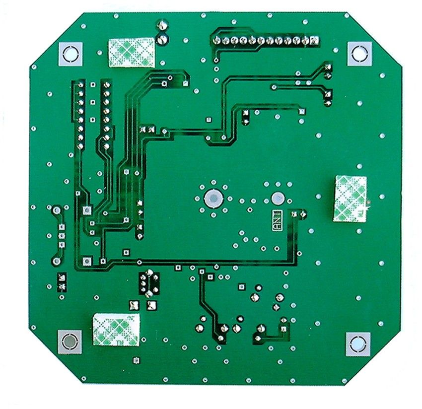
31 Oct. 2001 Page 2 of 3 Software v. 4.0 Ph: 520-884-7981 Toll-free: 1-800-MIDIANS Fx: 520-884-0422 2302 E. 22 nd St., Tucson, AZ 85713, USA [email protected] 8. After the last data pack is transmitted the SPVD instantly measures the Earth’s magnetic field and saves it to memory. Once auto-calibration has occurred (last data pack was transmitted) the unit should not be rotated or tilted anymore. Doing so will require the need to tip the unit on its side and repeat the calibrating process. While passing a magnet over the SPVD, use the scanner and receiver at the controller and once again verify arrival and departure pulses. 9. Put cold patch or hot mix over the detector and wave a magnet over the detector to simulate a detection to verify again that the receiver is receiving the packets. 10. After these steps are completed, test the unit with a vehicle. You may also want to use the tire of the vehicle to pack the cold patch. TECHNICAL NOTES: 1. The FCC has allocated 20 frequencies from 47.02 to 47.40 MHz for use by wireless vehicle detectors. The FCC does not regulate spurious emissions from traffic controllers; therefore many controllers will generate RF noise on the 47 MHz band (usually 1 or 2 of the 20 frequencies). Midian recommends using a handheld scanner to scan the cabinet for RF noise, to determine if there are any channels with birdies generated by the controller. Midian will also do an FCC database check for any licensed frequencies in the area. Midian will then avoid any licensed frequencies or those that have been determined to have birdies at that intersection. 2. The SPVD-2 PC board has a dipswitch in one corner to adjust the sensitivity of the detection zone. SW1 is closest to the corner. The first 3 positions on the switch adjust the sensitivity. With no switches selected the detection zone is comparable to a six by six loop. The sensitivity can be increased or decreased by adjusting the switch as indicated in the Sensitivity Table located on the next page. If the departure pulse is not required, turning SW4 on will activate pulse mode, eliminating the departure pulse. This will reduce battery consumption and add another year to the battery life. This is typically done if presence detection is not required. You must also turn on pulse mode at the receiver. 3. If the detector will be installed within approximately 100 feet of the antenna, the power can be lowered to extend the battery life. This is accomplished by adjusting switches 6 & 7 on the dipswitch. With pins 6 & 7 both in the on position the power output is 95mW, with 6 on and 7 off 45 mW, and with 6 off and 7 on 85mW. 4. Switch 8 works as a power on/off switch. No power will be supplied to the board with the switch in the off position. SPVD OPERATION: The SPVD-2 uses a dual-axis magnetometer to measure the Earth’s magnetic field. IC-2 is a 12-bit AD converter that converts the analog information to digital data for use by the microprocessor IC-1. IC-1, IC-2 and the magnetometer receive their power from IC-3. When the microprocessor determines a vehicle is present it turns on IC-4, a 6-volt regulator to power the transmitter. Transmission time is 20 msec. The micro also transmits a short data pack on Pin 12 during the last half of the 20 msec to tell the receiver that a vehicle has arrived. R30 and C21 acts as a splatter filter before data hits the true FM varactor diode D8. D7AB, R31 and R32 set the bias point for D8 and provides temperature compensation for oscillator Q2. Oscillator Q2 employs an 11.8 MHz crystal. L1 and C22 tune the oscillator Q2’s output to the fourth harmonic. Q3 and Q4 amplify and buffer the 47 MHz signal from the oscillator and then drive the final amplifier IC-5. Inductor L-5 and capacitor C36 tune the base circuit of IC-5. L7 and C40 tune IC-5 to 47.XX MHz while C41, L8, C42 and C44 act as a low-pass filter and impedance matching to the spiral antenna. Switches 6 and 7 allow the user to select Hi or Low power options. TUNING PROCEDURE: Oscillator Q2’s collector tank circuit (L2) is adjusted by C26. Tune for a peak level on TP9. Buffer amp Q3’s collector tank circuit (L3 & C28) is tuned using L3 and adjusting TP10 for a peak indication. Buffer amp Q4’s collector tank circuit (L4 & C31) is tuned using L4 and adjusting TP11 for a peak indication. The input to IC-5 is adjusted using L5 and C36 and tuning for maximum output power on J1 antenna connector. IC-5’s collector tank circuit is tuned using C40 and peaking for maximum RF power output. C44 helps match the low-pass filter to the antenna connector. Tune C44 for peak power on the antenna connector.
Test Report
APPLICANT: MIDIAN ELECTRONICS INC. FCC ID: NOWSPVD-2 REPORT #: T:\M\MIDIAN\1100au\1100auTestReport.doc TABLE OF CONTENTS LIST TABLE OF CONTENTS LIST APPLICANT: MIDIAN ELECTRONICS INC. FCC ID: NOWSPVD-2 TEST REPORT: PAGE 1......COVER SHEET - GENERAL INFORMATION & TECHNICAL DESCR. PAGE 2......TECHNICAL DESCRIPTION CONTINUED & RF POWER OUTPUT PAGE 3......RF POWER OUTPUT AND MODULATION CHARACTERISTICS PAGE 4......OCCUPIED BANDWIDTH PAGE 5......OCCUPIED BANDWIDTH PLOT – CW PAGE 6......OCCUPIED BANDWIDTH PLOT PAGE 7......SPURIOUS EMISSIONS AT ANTENNA TERMINALS PAGE 8......METHOD OF MEASURING SPURIOUS EMISSIONS AT ANTENNA TERM. PAGE 9......FIELD STRENGTH OF SPURIOUS EMISSIONS PAGE 10.....METHOD OF MEASURING RADIATED SPURIOUS EMISSIONS PAGE 11.....FREQUENCY STABILITY PAGE 12.....LIST OF TEST EQUIPMENT EXHIBITS CONTAINING: EXHIBIT 1.........FCC ID LABEL SAMPLE EXHIBIT 2.........SKETCH OF LOCATION EXHIBIT 3.........SCHEMATIC EXHIBIT 4.........BLOCK DIAGRAM EXHIBIT 5A-5B.....OPERATIONAL DESCRIPTION EXHIBIT 6A-6C.....USER’S MANUAL INCLUDING TUNIG PROCEDURE EXHIBIT 7.........EXTERNAL PHOTO – SIDE VIEW EXHIBIT 8.........EXTERNAL PHOTO – TOP VIEW EXHIBIT 9.........INTERNAL PHOTO – CHASSIS VIEW EXHIBIT 10........INTERNAL PHOTO – COMPONENT VIEW EXHIBIT 11........INTERNAL PHOTO – SOLDER VIEW EXHIBIT 12........TEST SET UP PHOTO APPLICANT: MIDIAN ELECTRONICS INC. FCC ID: NOWSPVD-2 REPORT #: T:\M\MIDIAN\1100au\1100auTestReport.doc Page 1 of 13 GENERAL_INFORMATION_REQUIRED FOR_TYPE_ACCEPTANCE 2.1033 MIDIAN ELECTRONICS INC. will sell the (c)(1)(2) FCC ID: NOWSPVD-2 VHF transceiver in quantity, for use under FCC RULES PART 90. (3) Instruction book. The instruction manual is included as EXHIBIT 6A-6C. 2.1033 (c) TECHNICAL DESCRIPTION 2.1033 (4) Type of Emission: 7K3F2D For 25 kHz 7K3F2D For 12.5 kHz For 25kHz and 12 kHz 90.209(b)(5) Bn = 2M + 2DK M = 4,000 Bits per second D = 1.65KHz (Peak Deviation) K = 1 Bn = 2(4000/2) + 2(1.65K)(1) = 4.0K + 3.3K = 7.3K ALLOWED AUTHORIZED BANDWIDTH = 20.0 kHz FOR 12.5Khz ALLOWED AUTHORIZED BANDWIDTH = 11.25 kHZ 2.1033 (5) Frequency Range: 30-50 MHz (6) Power Range and Controls:There are NO user Power controls. (7) Maximum Output Power Rating: 0.1 Watts , into a 50 ohm resistive load. (8) DC Voltages and Current into Final Amplifier: DC POWER INPUT FINAL AMPLIFIER ONLY Vce = 7.8 Volts Ic = .55 A (9) Tune-up procedure. The tune-up procedure is given in EXHIBIT 6A-6C. APPLICANT: MIDIAN ELECTRONICS INC. FCC ID: NOWSPVD-2 REPORT #: T:\M\MIDIAN\1100au\1100auTestReport.doc Page 2 of 12 2.1033 (10) Complete Circuit Diagrams: The circuit diagram is included as EXHIBIT 3. The block diagram is included as EXHIBIT 4. 2.1033(c)(10) Description of all circuitry and devices provided for determining and stabilizing frequency is included in the circuit description in EXHIBIT 5. 2.1033(c)(11) A photograph or drawing of the equipment identification label is shown in Exhibit 1. 2.1033(c)(12) Photographs of the equipment of sufficient clarity to reveal equipment construction and layout and label location are shown in Exhibit 7-11. 2.1033(c)(13) For equipment employing digital modulation, a detail description of the modulation technique. This UUT uses FSK to modulate the transmitter. 2.1033(c)(14) data required for 2.1046 to 2.1057 See Below 2.1046(a) RF_power_output . RF power is measured by connecting a 50 ohm, resistive wattmeter to the RF output connector. With a nominal battery voltage of 7.8 VDC, and the transmitter properly adjusted the RF output measures : POWER MEASUREMENTS: INPUT POWER – HIGH: (7.8V)(0.550A) = 4.29 Watts INPUT POWER – LOW: (7.8V)(0.2A) = 1.56 Watts OUTPUT POWER: HIGH: .10 Watts LOW: .038 Watts APPLICANT: MIDIAN ELECTRONICS INC. FCC ID: NOWSPVD-2 REPORT #: T:\M\MIDIAN\1100au\1100auTestReport.doc Page 3 of 12 METHOD OF MEASURING RF POWER OUTPUT Transmitter 50 ohm under test Resistive Wattmeter Power Supply 2.1047(a) Voice Modulation_characteristics: NOT APPLICABLE, F2 type of emission. 2.1049 Audio Low Pass Filter This UUT does not have a low pass filter. 2.1049 Occupied_bandwidth: 90.210(c,) (Emission Mack C) For transmitters that are not equipped with an audio low pass filter pursuant to S90.211(b), the power of any emission must be attenuated below the unmodulated carrier output power as follows; (1) On any frequency removed from the center of the authorized bandwidth by a displacement frequency(fd in kHz) of more than 5kHz but not more Than10 kHz: At least 83 log(fd/5)dB; (2)ON any frequency removed from the center of the authorized bandwidth by a displacement frequency(fd in kHz) of more than 10kHz, but not more than 250% of the authorized bandwidth: At least 29 log(fd2/11)dB or 50dB, whichever is the lesser attenuation; (3) On any frequency removed from the center of the authorized bandwidth by more than 250% of the authorized bandwidth: At least 43+10 log(Po)dB. APPLICANT: MIDIAN ELECTRONICS INC. FCC ID: NOWSPVD-2 REPORT #: T:\M\MIDIAN\1100au\1100auTestReport.doc Page 4 of 12 90.210(d) Emission Mask D - 12.5 kHz channel bandwidth equip- ment. For transmitters designed to operate with a 12.5 kHz channel bandwidth, any emission must be attenuated below the power (P) of the highest emission contained within the authorized bandwidth as follows: (1) On any frequency from the center of the authorized bandwidth f0 to 5.625 kHz removed from f0: Zero dB. (2) On any frequency from the center of the authorized bandwdith by a displacement frequency (fd in kHz) of more than 5.625 kHz but no more than 12.5 kHz: At least 7.27 (fd - 2.88 kHz) dB. (3) On any frequency removed from the center of the authroized band- width by a displacement frequency (fd in kHz) of more than 12.5 kHz: At least 50 + 10 log (P) dB or 70 dB, whichever is the lesser attenua- tion. Data in the plots shows that on any frequency removed from the assigned frequency by more than 50%, but not more than 100%: At least 25dB. On any frequency removed from the assigned frequency by more than 100%, but not more than …
Text truncated - open the document above for the full version.
Contact Information
Applicant
Chuck Soulliard
Test Firm
Timco Engineering, Inc.S Sanders
Technical Specifications
| # | Rule Parts | Frequency Range | Power Output | Emission | Tolerance |
|---|---|---|---|---|---|
| 2 | 9 | 47.02 MHz - 47.4 MHz | 38.00 mW | 7K3F2D | 0.005 % |
Other Applications from Midian Electronics Inc
NOWSPVD-1
Jan 13, 1998TNB - Licensed Non-Broadcast Station Transmitter
Equipment Class
TNB - Licensed Non-Broadcast Station TransmitterNOWSPVDREC
Dec 16, 1997CYY - Communications Receiver used w/Pt 15 Transmitter
Equipment Class
CYY - Communications Receiver used w/Pt 15 Transmitter