NQ3TCP-COData Transmitter
Smith Meter Inc
Click to zoom
Application Details
- Equipment Class
- DXC - Part 15 Low Power Transceiver, Rx Certified
- Date of Grant
- Jul 21, 1998
- Application Purpose
- Original Equipment
- Date of Application
- Apr 27, 1998
- Equipment Note
- Data Transmitter
- Frequency Range
- 916.50000000 - 916.50000000
- Company
- Smith Meter Inc
- Country
- United States
Documents & Files
Document Text
Text extracted from the exhibit documents filed with the FCC. Open a document above to read the original.
Attestation Statements
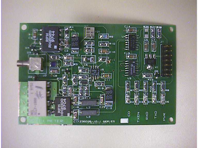
RESPONSE TO REQUEST FOR ADDITIONAL INFORMATION ON FCCID:NQ3TCP-CO FCC Reference Number: 1463July 7, 1998 The following are the responses to the request for additional information as described by Rich Fabina, FCC Application Processing Branch. The field strength measurements and corrections for range losses were performed by James Pollock of Smith Electronics, Inc. at the Smith Electronics Test Facility in Cleveland, Ohio on July 6, 1998. The resulting data is tabulated in this response. 1. The field strength of the fundamental was re-measured employing a quasi-peak detector function. In addition, the transmitter was configured for a continuous waveform (cw) output in order to eliminate any averaging effect. The 916.65 Mhz fundamental peak field strength level is 92.8 dBμV/m or 43,562 μV/m. This is less than the specified 50,000 μV/m limit. 2. The calculated average field strength levels for the 2nd through the 10th harmonics are as follows; Freq. (MHz) FS (dBuV/m) Duty Cycle Factor (dB) FSadj (dBuV/m) FSadj (uV/m) FSlim (uV/m) 1833.3058.1 @1m12.445.7192.81,500 2749.9550.9 @1m12.438.584.11,500 3666.6059.3 @1m12.446.9221.31,500 4583.2555.8 @1m12.443.4147.91,500 5499.9059.4 @1m12.447.0223.91,500 6416.5556.4 @1m12.444.0158.51,500 7333.20<[email protected]<52.6<426.63,000 8249.85<67.2 @.5m12.4<54.8<549.53,000 9166.50<65.8 @.5m12.4<53.4<467.73,000 Note: The Field Strength Limits have been adjusted to reflect measurements taken at 1 m and 0.5 m distances. Measurements were taken at these distances to provide an observed signal strength greater than the noise floor of the HP8593EM spectrum analyzer. 3. A Duty Cycle Factor resulting from ON-OFF Keying and pulse train duration was calculated to be 12.4 dB. The receiver requires a dc balanced bit pattern in order to establish and maintain a threshold level for the bit slice detector. The data to transmit are ASCII characters from 0 to 255 decimal in value. These 256 characters have been mapped into 10 bit dc balanced bit patterns. Start and stop bits supplement the translated character into 12 bits in length. To establish a dc residue on the bit slice input an 8 character preamble is transmitted. The preamble character is 0665hex. The bit pattern for this character is dc balanced. DC balancing yields a duty cycle of 0.5. Preamble Character Breakdow n b1b2b3b4b5b6b7b8b9b10b11b12 001100110101 6h6h5h startd9d8d7d6d5d4d3d2d1d0stop Character Map - 8 to 10 bit (start and stop bits included) 0123456789ABCDEF 0 06F 077 07B 0AF 0B7 0BB 0BD 0CF 0D7 0DB 0DD 0E7 0EB 0ED 0F3 0F5 1 12F 137 13B 13D 14F 157 15B 15D 167 16B 16D 173 175 179 18F 197 2 19B 19D 1A7 1AB 1AD 1B3 1B5 1B9 1C7 1CB 1CD 1D3 1D5 1D9 1E3 1E5 3 1E9 22F 237 23B 23D 24D 24F 257 25B 25D 267 26B 26D 273 275 279 4 28F 295 297 29B 29D 2A5 2A7 2AB 2AD 2B3 2B5 2B9 2C7 2C9 2CB 2CD 5 2D3 2D5 2D9 2E3 2E5 2E9 2F1 30F 317 31B 31D 325 327 32B 32D 333 6 335 339 347 349 34B 34D 353 355 359 363 365 369 371 387 38B 38D 7 393 395 399 3A3 3A5 4A9 3B1 3C3 3C5 2C9 3D1 42F 437 43B 43D 44F 8 457 45B 45D 467 46B 46D 473 475 479 48F 497 499 49B 49D 4A5 4A7 9 4A9 4AB 4AD 4B3 4B5 4B9 4C7 4CB 4CD 4D3 4D5 4D9 4E3 4E5 4E9 4F1 A 50F 517 51B 51D 527 52B 52D 533 535 539 547 54B 54D 553 555 559 B 55B 563 565 569 56B 56D 571 587 58B 58D 593 595 599 5A3 5A5 5A9 C 5AD 5B1 5B5 5C3 5C5 5C9 5D1 5E1 617 61B 61D 627 62B 62D 633 635 D 639 647 64B 64D 653 655 659 65B 663 5B3 669 66B 66D 671 687 68B E 68D 693 695 699 6A3 6A5 6A9 6B1 6C3 6C5 6C9 6D1 6D5 6E1 70B 70D F 713 715 719 723 725 729 731 743 745 749 751 761 785 789 791 7A1 The baud rate of the communications is 19.2 kbaud resulting in a bit time of 50 μs. The maximum data characters in a packet is 64. The data is preceded with STX, FROM, TO, and NUM characters then followed by a four character checksum (refer to TCP-CO External Communications Specification for exact protocol format). Along with the 8 preamble characters, a total of 80 characters may be in the packet. With 12 bits per character, 80 characters results in 960 bit times or 48 ms. DC balancing reduces the cumulative pulse duration by 50% to a value of 24 ms. This 24 ms ‘ON’ time over a 100 ms period results in a duty cycle factor of 12.40 dB. This device uses only 32 of the maximum 64 characters in its largest packet. This increases the duty cycle factor by 6 dB to 18.4 dB. The calculation in #2 above demonstrates that the device complies even when evaluated at its theoretical maximum packet size. 4. A JPEG image file of the radio board without the shield is attached to this document as NQ3TCP.JPG. If there are any further questions or discrepancies, please contact Richard Miller via e-mail (millerr%[email protected]). I will submit a contact change through the website. FUNDAMENTAL AND SPURIOUS EMISSIONS TCPCO TRANSMITTER July 6, 1998 Freq. (Mhz) Value (dBμ μμ μV) AF (dB) CL (dB) FS (dBμ μμ μV/m) FS (μ μμ μV/m) Limit (μ μμ μV/m) *916.6562.0 @3m29.11.792.843,65250,000 [email protected],500 [email protected],500 [email protected],500 [email protected],500 [email protected],500 [email protected],500 7333.20<[email protected]<1,9723,000 8249.85<[email protected]<2,2903,000 9166.50<[email protected]<1,9503,000 * = Fundamental Frequency AF = Antenna Factor CL = Coax Loss Factor FS = Field Strength For measurement purposes, the transmitter was fixed to emit a non-modulated carrier signal. For this signal, peak,quasi-peak and average measurements should produce the same readings on the meter. This was verified with both the receiver and the spectrum analyzer used. The fundamental frequency was measured using a tuned dipole antenna and a receiver with a quasi-peak detector. The harmonics were measured with a double ridged guide horn antenna and the HP8593EM spectrum analyzer. Peak measurements were made using a 1 Mhz resolution bandwidth and a 100 kHz video bandwidth to reduce the instrument noise level to permit the low level signals to be observed. As pr…
Text truncated - open the document above for the full version.
Contact Information
Applicant
G. Bruce Kernes(Sr. Electronics Engineer)
Test Firm
Smith Electronics, Inc.James Pollock
Technical Specifications
| # | Rule Parts | Frequency Range | Power Output | Tolerance |
|---|---|---|---|---|
| 1 | 15C | 916.5 MHz - 916.5 MHz | - | % |
Other Applications from Smith Meter Inc
NQ3RFT
Jul 21, 1998Data Collection Transmitter
Equipment Class
DXT - Part 15 Low Power Transceiver, Rx Verified