NQH-GCRFHRH9TXRemote Control Transmitter for Crane
Robinson Engineering Company Inc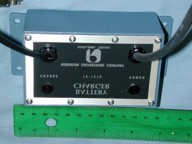
Click to zoom
Application Details
- Equipment Class
- DXX - Part 15 Low Power Communication Device Transmitter
- Date of Grant
- Jan 20, 2003
- Application Purpose
- Original Equipment
- Date of Application
- Jan 20, 2003
- Equipment Note
- Remote Control Transmitter for Crane
- Frequency Range
- 910.70000000 - 917.70000000
- Country
- United States
Documents & Files
Document Text
Text extracted from the exhibit documents filed with the FCC. Open a document above to read the original.
Users Manual
This equipment complies with Part 15 of the FCC rules any changes or modifications not expressly approved by the manufacturer could void the user's authority to operate the equipment.
Block Diagram
BATTERY ASSEMBLY KEY SWITCH START/RESET ON OFF AUX BT1T2H1H2 ADDRESS PLUG MASTER PLUG CODER ASSEMBLYRF ASSEMBLY EXTERNAL CONTROLS JUNCTION BOARD FUNCTION CONTROLS ANTENNA INTERNAL COMPONENTS FIG. 3-1: BLOCK DIAGRAM, TRANSMITTER Nom. 915 MHz NOTE: The Voltage Controlled Oscillator is integral to the radio chip. There is no external oscillator. The VCO in the chip is a direct VCO. 12.7 MHz clock oscillator
External Photos
Battery Charger Top view of controls Left Side Right Side
ID Label/Location Info
Label goes here on front face of equipment
Internal Photos
Internal View Backplane Showing mounting of Radio Board Backplane/Interface card Control Card Back Controal Card Front
Operational Description
Operational Description The transmitter is a battery operated FSK radio transmitter. Incorporated with the transmitter is an antenna and disposable batteries. Transmitter carrier frequency is PLL controlled. The frequency is changed via DIP switches. When the DIP switch settings are changed, coded control signals are sent to the receiving equipment via the antenna. All of the frequency determining components are on the single-chip transmitter. The equipment is used for remote control of a crane, typically in an industrial environment.
Schematics
12-1827 A
Test Report
Master: NemkoPT15249A Date: April 19, 1999 Nemko Test Report: 2L0344RUS1 Applicant: Robinson Engineering Co. 1914 Silver Street Garland, Texas 75042 Equipment Under Test: CraneBoss Remote Control Transmitter (E.U.T.) In Accordance With: FCC Part 15, Subpart C, 15.249 For 900 MHz Transmitters Tested By: Nemko Dallas Inc. 802 N. Kealy Lewisville, Texas 75057-3136 Authorized By: David Light, Wireless Group Supervisor Date: 7/17/02 Total Number of Pages: 22 Nemko Dallas FCC PART 15, SUBPART C FOR 900 MHz TRANSMITTERS EQUIPMENT: CraneBoss Remote Control Transmitter PROJECT NO.: 2L0344RUS1 Page 2 of 22 Table Of Contents Section 1. Summary Of Test Results........................................................... 3 Section 2. General Equipment Specification................................................ 6 Section 3. Powerline Conducted Emissions................................................. 8 Section 4. Radiated Emissions.................................................................... 12 Section 5. Occupied Bandwidth.................................................................... 16 Section 6. Test Equipment List ..................................................................... 19 ANNEX A TEST DIAGRAMS ........................................................................... 20 Nemko Dallas FCC PART 15, SUBPART C FOR 900 MHz TRANSMITTERS EQUIPMENT: CraneBoss Remote Control Transmitter PROJECT NO.: 2L0344RUS1 Page 3 of 22 Section 1. Summary Of Test Results Manufacturer: Robinson Engineering Co. Model No.: CraneBoss Remote Control Serial No.: S01 General: All measurements are traceable to national standards. These tests were conducted on a sample of the equipment for the purpose of demonstrating compliance with FCC Part 15.249. All tests were conducted using measurement procedure ANSI C63.4-1992. Radiated Emissions were made on an open area test site. New Submission Production Unit Class II Permissive Change Pre-Production Unit D S C Equipment Code This test report relates only to the item(s) tested. The following deviations from, additions to, or exclusions from the test specifications have been made. None NVLAP LAB CODE: 100426-0 NEMKO Dallas Inc. authorizes the above named company to reproduce this report provided it is reproduced in its entirety and for use by the company’s employees only. Any use which a third party makes of this report, or any reliance on or decisions to be made based on it, are the responsibility of such third parties. NEMKO Dallas Inc. accepts no responsibility for damages, if any, suffered by any third party as a result of decisions made or actions based on this report. This report applies only to the items tested. Nemko Dallas FCC PART 15, SUBPART C FOR 900 MHz TRANSMITTERS EQUIPMENT: CraneBoss Remote Control Transmitter PROJECT NO.: 2L0344RUS1 Page 4 of 22 Summary Of Test Data NAME OF TEST PARA. NO. RESULT Conducted Emissions 15.207 Complies Radiated Emissions 15.249 Complies Footnotes: Modifications made During Testing: 1) 10pF capacitor added at antenna to reduce harmonic levels 2) Shield added over RF section. Refer to photos Nemko Dallas FCC PART 15, SUBPART C FOR 900 MHz TRANSMITTERS EQUIPMENT: CraneBoss Remote Control Transmitter PROJECT NO.: 2L0344RUS1 Page 5 of 22 Nemko Dallas FCC PART 15, SUBPART C FOR 900 MHz TRANSMITTERS EQUIPMENT: CraneBoss Remote Control Transmitter PROJECT NO.: 2L0344RUS1 Page 6 of 22 Section 2. General Equipment Specification Operating Frequency(ies) of Sample: 910.7-917.7 MHz Tunable Bands: N/A Number of Channels: Eight Channel Spacing: 1 MHz Modulation: FSK User Frequency Adjustment: Dip Switches Integral Antenna Yes No Note: If antenna is not integral to transmitter explain method of attachment and type of unique connector: Nemko Dallas FCC PART 15, SUBPART C FOR 900 MHz TRANSMITTERS EQUIPMENT: CraneBoss Remote Control Transmitter PROJECT NO.: 2L0344RUS1 Page 7 of 22 Description of Operation: The transmitter is a simple FSK modulated transmitter that transmits control data signals to a remote receiver for the purpose of controlling crane systems. The transmitted signal falls wholly within the 902 – 928 MHz ISM band. System Diagram Remote Control Transmitter Remote Receiver Nemko Dallas FCC PART 15, SUBPART C FOR 900 MHz TRANSMITTERS EQUIPMENT: CraneBoss Remote Control Transmitter PROJECT NO.: 2L0344RUS1 Page 8 of 22 Section 3. Powerline Conducted Emissions NAME OF TEST: Powerline Conducted Emissions PARA. NO.: 15.207 TESTED BY: Tom Tidwell DATE: 7/17/2002 Minimum Standard: Frequency Maximum Powerline Conducted RF Voltage (MHz) (μV) (dBμV) 0.45 - 30.0 250 48 Test Results: Complies. See attached graph(s). Measurement Data: See attached graph(s). Method of Measurement: (Procedure ANSI C63.4-1992) Measurements were made using a spectrum analyzer with 10 kHz RBW, Peak Detector. Any emissions that are close to the limit are measured using a test receiver with 10 kHz bandwidth, CISPR Quasi-Peak Detector. Nemko Dallas FCC PART 15, SUBPART C FOR 900 MHz TRANSMITTERS EQUIPMENT: CraneBoss Remote Control Transmitter PROJECT NO.: 2L0344RUS1 Page 9 of 22 Dallas Headquarters: 802 N. Kealy Lewisville, TX 75057 Tel: (972) 436-9600 Fax: (972) 436-2667 Nemko Dallas, Inc. Data Plot Page 1 of 2 Complete X Job No.:2L0344 Date:7/17/2002Preliminary: Specification:15.209Temperature(°C):22 Tested By:Tom TidwellRelative Humidity(%)50 E.U.T.: Configuration: Sample Number:1 Location:Lab 4RBW: 10 kHzMeasurement Detector Type:PeakVBW: 10 kHz Distance: NAm Test Equipment Used Antenna: LISN969 Pre-Amp: Cable #1:1266 Filter:758Cable #2:1999 Receiver:1036Cable #3: Attenuator #1 Cable #4: Attenuator #2: Limiter:674 Additional equipment used: Measurement Uncertainty:+/-1.7 dB Notes: NEUTRAL LINE PEAK DETECTOR / AVERAGE LIMIT Powerline Conducted Emissions TRANSMITTER CHARGING Nemko Dallas FCC PART 15, SUBPART C FOR 900 MHz TRANSMITTERS EQUIPMENT: CraneBoss Remote Control Transmitter PROJECT NO.: 2L0344RUS1 Page 10 of 22 Dallas Headquarters: 802 N. Kealy …
Text truncated - open the document above for the full version.
Test Setup Photos
Conducted Emissions – Front View Conducted Emissions – Side/Rear View Radiated Emissions – Worst-case configuration Radiated Emissions – Back View
Contact Information
Applicant
William B. Robinson(President)
Technical Contact
Nemko Dallas, Inc.Tom Tidwell
[email protected]972-436-9600
802 N. Kealy · Lewisville, Texas · United States
Non-Technical Contact
Nemko Dallas, Inc.Tom Tidwell
[email protected]972-436-9600
Test Firm
Nemko Dallas, Inc.Michael Cantwell
Technical Specifications
| # | Rule Parts | Frequency Range | Power Output |
|---|---|---|---|
| 1 | 15C | 910.7 MHz - 917.7 MHz | - |
Other Applications from Robinson Engineering Company Inc
NQHCBNT900TRX
Sep 01, 2015Craneboss Remote Control Transmitter
Equipment Class
DXX - Part 15 Low Power Communication Device Transmitter