NRM93900 Mhz Cordless Phone
Philips Consumer Communications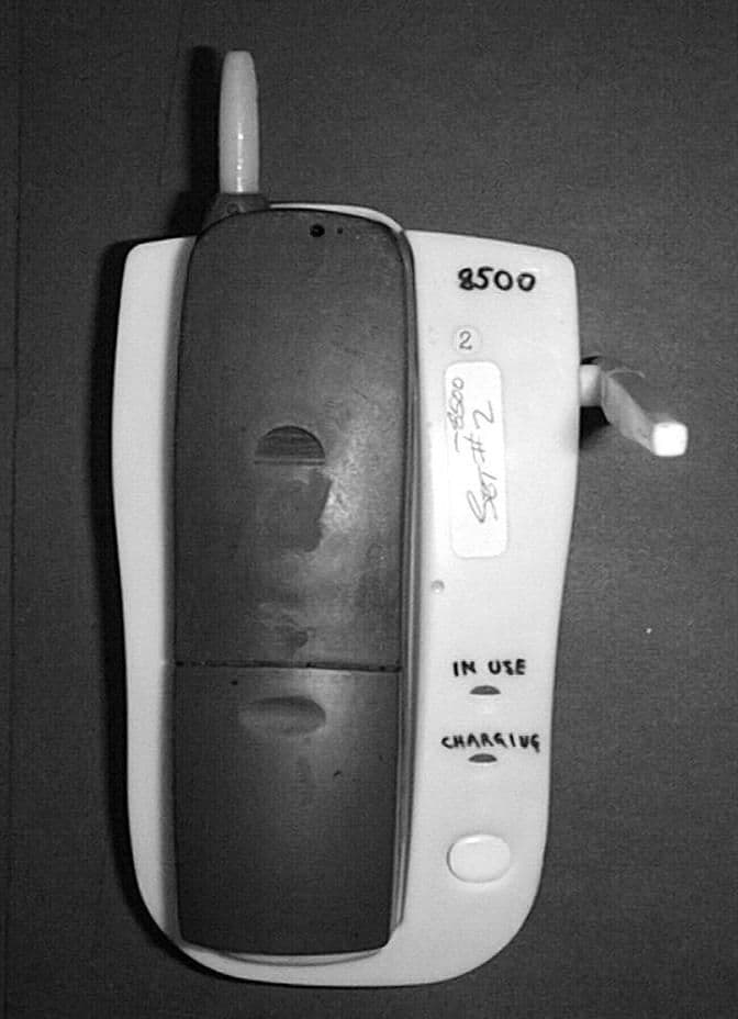
Click to zoom
Application Details
- Equipment Class
- DXT - Part 15 Low Power Transceiver, Rx Verified
- Date of Grant
- Nov 29, 1998
- Application Purpose
- Original Equipment
- Date of Application
- Sep 21, 1998
- Equipment Note
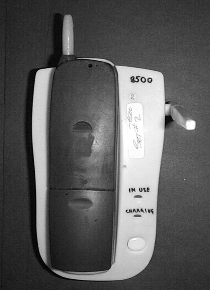
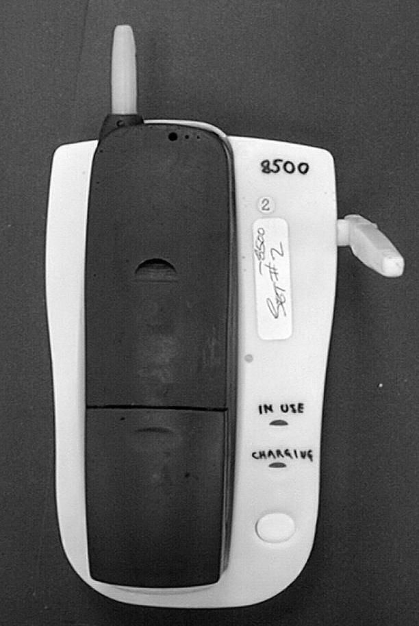
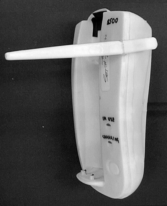
- 900 Mhz Cordless Phone
- Frequency Range
- 924.92800000 - 927.36000000
- Country
- United States
Documents & Files
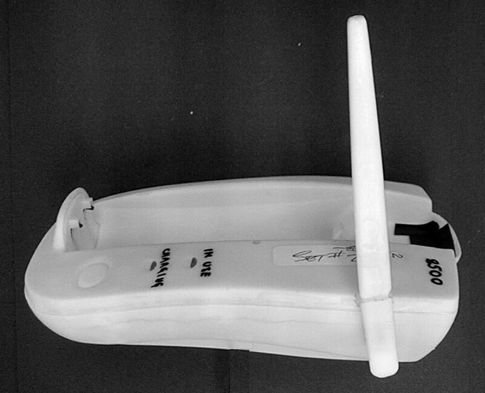
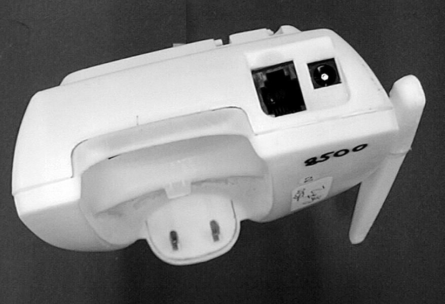
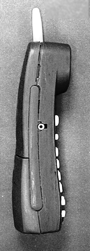
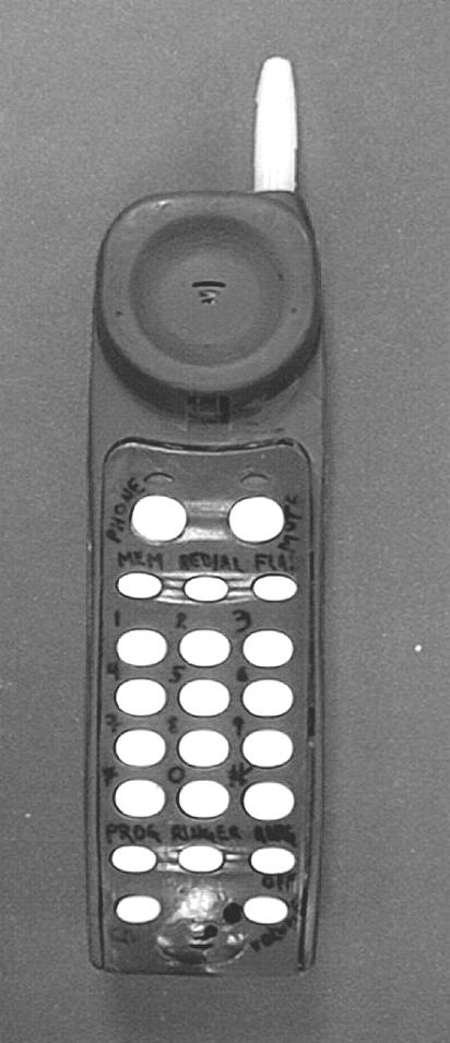
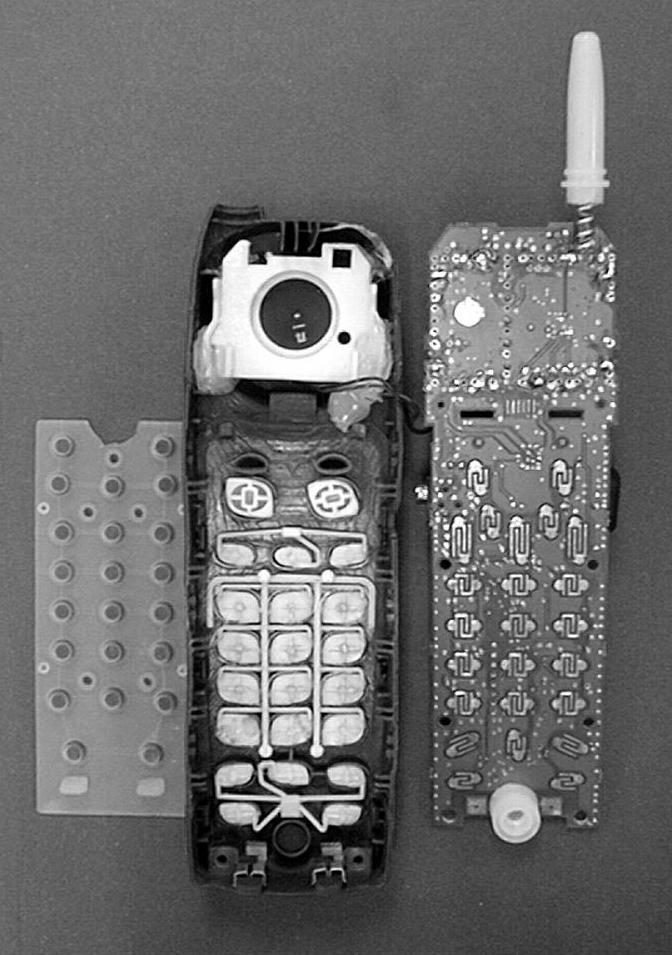
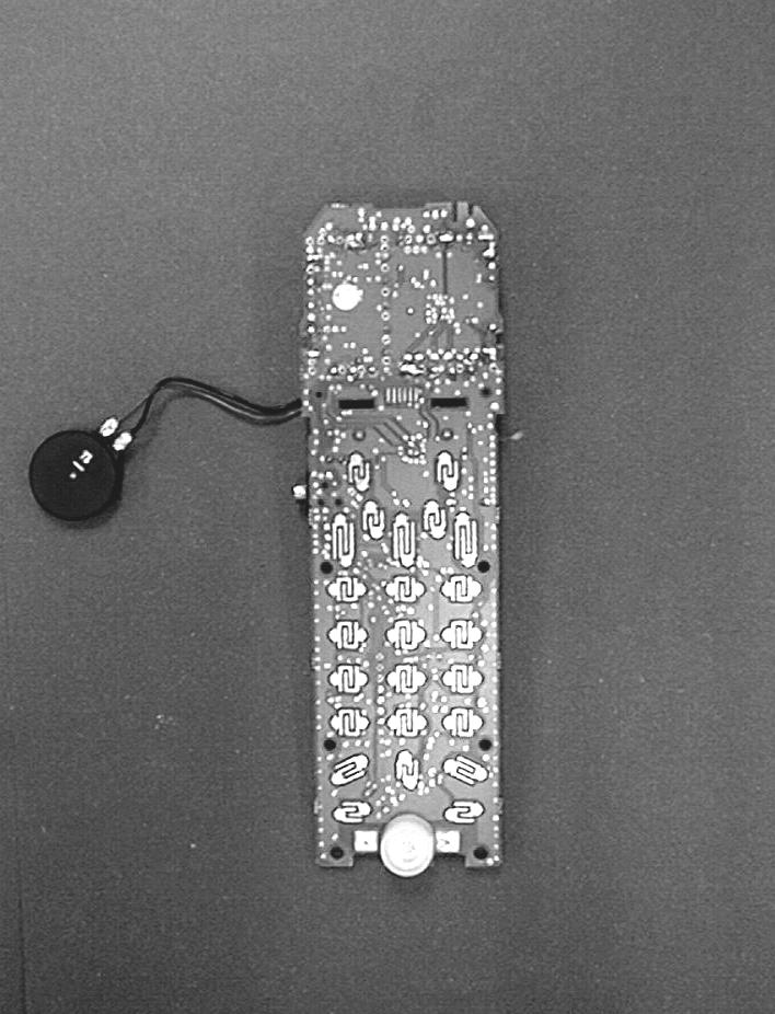
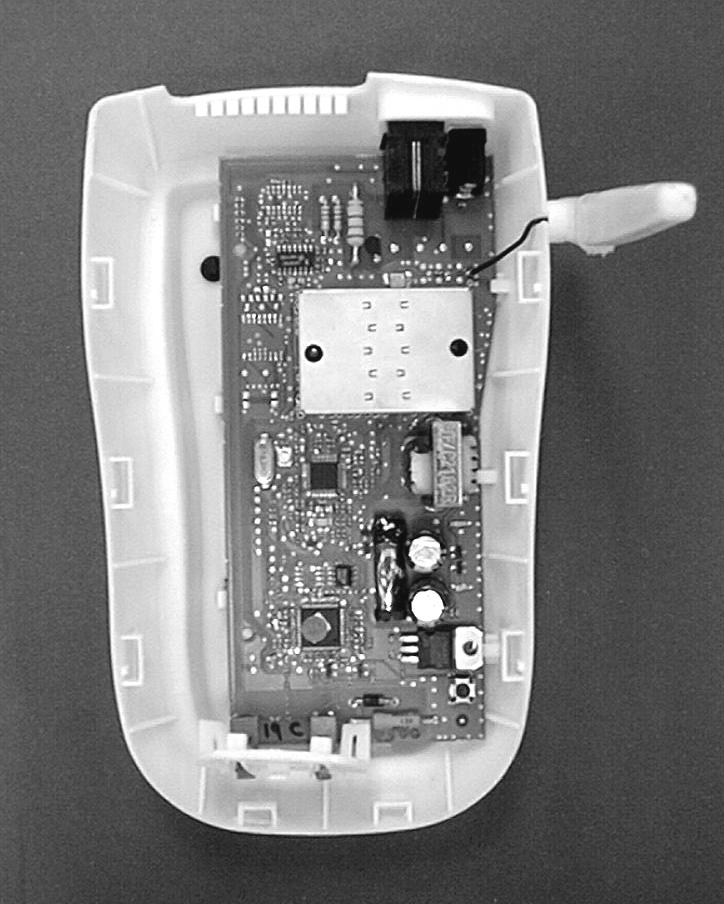
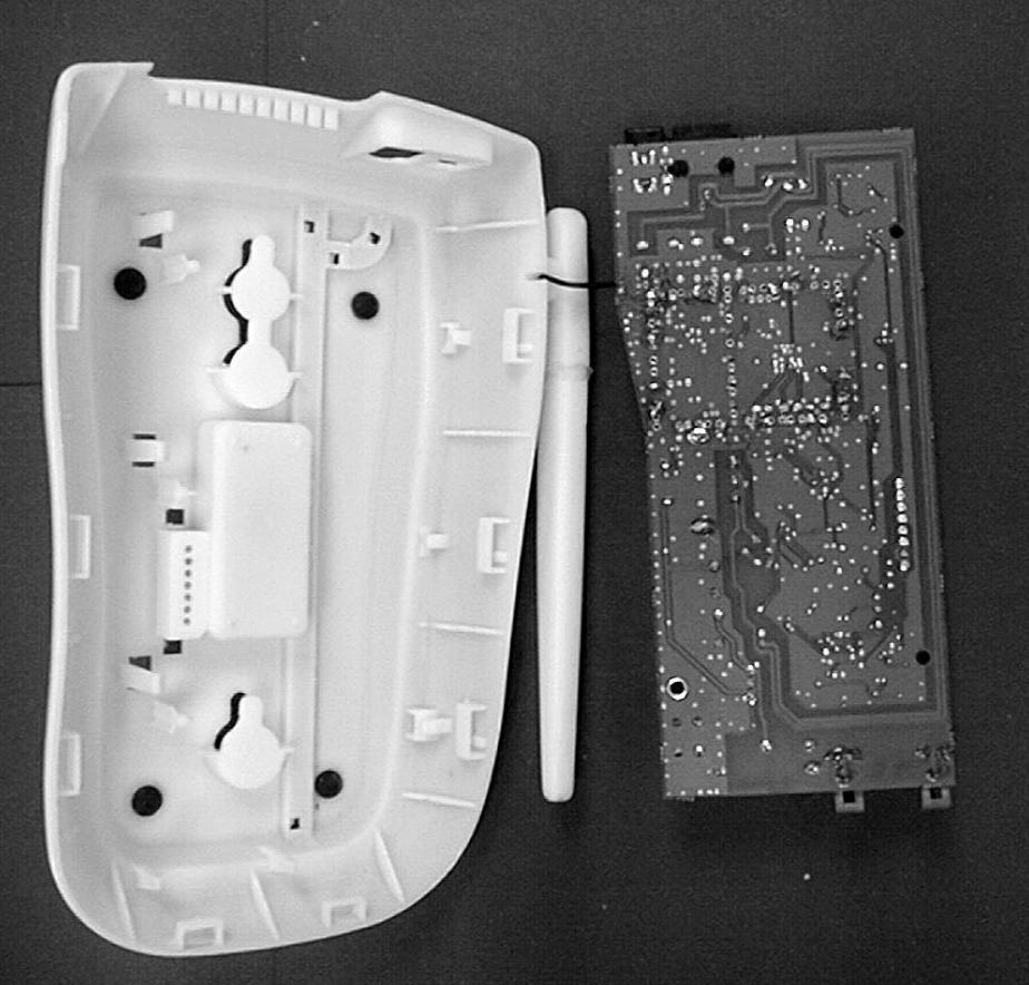
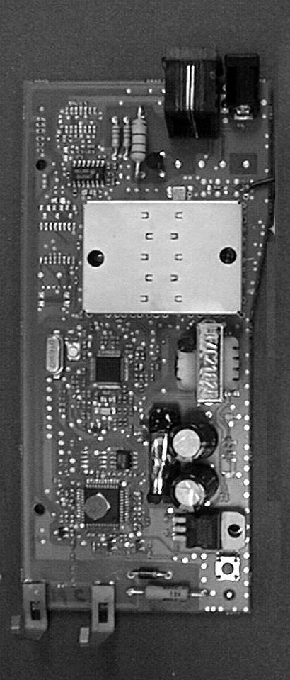
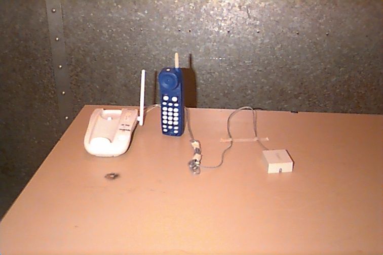
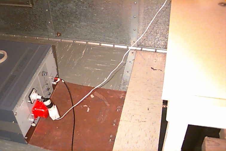
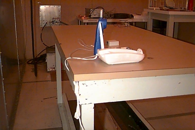
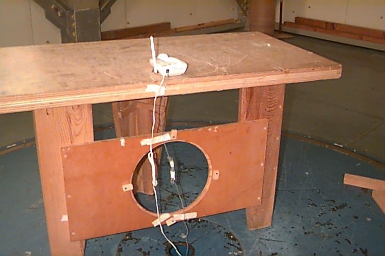
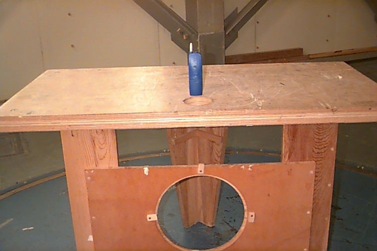
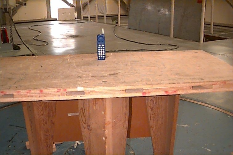
Document Text
Text extracted from the exhibit documents filed with the FCC. Open a document above to read the original.
Users Manual
User’s Manual for 900 MHz Cordless Telephone 9301 Fold open this manual for information about this product’s installation and operation. Please read Part 1 – Important Product Information, included in this package. Part 2 © 1998 Philips Consumer Communications L.P. All rights reserved. Printed in Mexico. 848244190 Issue 1AT&T 1 1 INSTALLATION Standard electrical outlet Modular telephone jack Power cord Long telephone line cord Table/Desk Installation Power cord Modular telephone jack Standard electrical outlet The instructions below are for both table and wall installation. 1Choose a spot near an electrical outlet and a telephone jack. This phone requires a modular telephone jack and a standard electrical outlet (110v AC) not controlled by a wall switch. 2Install the handset battery. (For an illustration of battery installation, see BATTERIES.) •Remove the battery cover by pressing on the indentation and sliding downward. •Plug the battery pack connector into the handset, and place the battery pack and wires into the compartment. •Replace the battery cover by sliding it on its track up over the battery compartment until it snaps firmly in place. 3Connect the telephone line cord. Plug one end of the telephone line cord into the jack labeled TEL LINE on the back of the base. Plug the other end of the line cord into a modular jack. Make sure the plugs snap firmly in place. (If you are wall mounting the phone, use the short line cord, and press the excess cord in the groove on the bottom of the base.) 4Connect the power cord. Plug the power adapter into the jack labeled POWER on the back of the base. Loop the cord through the strain-relief grooves, and press the cord into the groove on the back of the base. Plug the AC adapter on the power cord into an electrical outlet. NOTE: Connect power to the base unit before placing the handset in the cradle. 5Mount the base on the wall. (WALL MOUNTING ONLY) Hold the base so the mounting knobs on the standard wall jack will fit into the holes on the bottom of the base. Slide the base down onto the knobs until it locks into place. 6Charge the handset batteries for six hours. Place the handset face up or face down in the base. The CHARGING light on the base goes on to show the handset is in the right position to charge the batteries. 7Check for dial tone. After the batteries are charged, pick up the handset. Check for a dial tone by pressing P; you should hear a dial tone. 8Set the dial mode. If you have touch tone service, the phone is ready to use as soon as the batteries are charged. If you have dial pulse (rotary) service you’ll need to change the Dialing mode. When the phone is off, press P G # # # 3 to set the dial mode to Dial Pulse. To return to touch tone dialing (with touch tone service), press P G # # # 8. Belt Clip If you wish, you can attach the belt clip to the cordless handset, following the illustrations below. (The handset cannot be charged in the face-up position if the belt clip is attached.) Short telephone line cord Wall Installation To Remove To Attach Strain-relief groove 2 IN CASE OF DIFFICULTY If you have difficulty operating this phone, try the suggestions below. If you still have trouble, call 1 800 722–9125. If the phone doesn’t work at all, check these items first: •Make sure the AC adapter is plugged into an outlet not controlled by a wall switch. •Make sure the telephone line cord is plugged firmly into the base unit and the modular jack. •Make sure the base antenna is fully upright. •If the handset does not beep when you press P, the battery might need charging. •Make sure the battery pack is installed correctly. •If you have dial pulse (rotary) service on your phone line, make sure the dial mode is set to Dial Pulse (see INSTALLATION). If the above suggestions don’t solve the problem, try re-initializing the handset and base: 1Disconnect the power to the base. 2Remove the handset battery pack. 3Wait a few minutes. 4Connect the power to the base. 5Insert the handset battery pack. 6Put the handset in the base to re-initialize. If you hear a two-beep signal when you try to use the handset: •You might be out of range. Move closer to the base and try again. •If moving closer to the base doesn’t help, try following the directions above for re-initializing the handset and base. If you hear noise or interference when using the phone: •Make sure the base antenna is fully upright. •You may be out of range. Move closer to the base. •Press and release h to change to another of the 20 channels available. If noise is exceptionally loud, move closer to the base before changing channels. •Household appliances plugged into the same circuit as the base can sometimes cause interference. Try moving the appliance or the base to another outlet. •The layout of your home or office might be limiting the operating range. Try moving the base to another location, preferably on an upper floor. •If the buttons don’t work, try placing the handset in the base for at least 15 seconds. If the phone does not ring when you receive a call: •Make sure the handset ringer is on. (Press to turn ringer on.) •Make sure the telephone line cord is connected firmly to the base and the telephone jack. •Make sure the AC adapter is plugged firmly into an outlet not controlled by a wall switch. •You might be too far from the base; move closer. •You might have too many extension phones on your telephone line to allow all of them to ring. Try unplugging some of them. If you hear other calls while using your phone: •Press h to change to another channel. •Disconnect the base from the modular jack and plug in a corded telephone. If you still hear other calls, the problem is probably in your wiring or local service. Call your local telephone service company. If you lose a call after changing channels: You were probably almost out of range. Move closer to the base before changing channels. Before placing another call, set the handset in the base for at least 15 seconds. If you …
Text truncated - open the document above for the full version.
Attestation Statements
FCC ID: NRM93 ATTESTATION STATEMENT As the party responsible for design control of the Philips Consumer Communications 900 MHz Cordless Telephone Model Crush 8500 product line,. I certify that all manufactured units will conform to the sample tested, and that the emissions data in test report should be typical of what can be expected from all manufactured units. Furthermore, I understand that any subsequent design changes to the product may invalidate the data in this report, and require re-verification of compliance with the rules set forth in 47 CFR § 15 . Attested By: Signature:__Anatoliy Marhelyuk______ Date: 09/23/98
Cover Letter(s)
FCC ID: NRM93 MEASUREMENT/TECHNICAL REPORT Philips Consumer Communications FCC ID: NRM93 September 24 th , 1998 This report concerns (check one): Original grant Class II change Equipment type: Cordless Telephone Request issue of grant (check one): _ Immediately upon completion of review. Defer grant per 47 CFR 0.457(d)(1)(ii) until _________. Philips Consumer Communiations. Name agrees to notify the Commission by ________ of the intended date of announcement of the product so that the grant can be issued on that date. Measurement procedure used: (check one) ANSI C63.4-1992 FCC/OET MP-4(1987) Other If other, describe:47 CFR 15 Application for Certification Applicant for this device: prepared by: Cayetano Chavez Philips Consumer Communications, Inc. E123 246 Industrial Way West Eatontown, NJ 07724-2206 Tel. (732)544-3264 Fax (732)544-2956 e-mail [email protected]
Cover Letter(s)
FCC ID: NRM93 Subject: Request for Confidentiality Date: July 13, 2001 FCC ID: NRM93 From: Cayetano Chavez To: Federal Communications Commission Equipment Authorization Branch 7435 Oakland Mills Road Columbia, MD 21046 To whom it may concern: On behalf of Philips Consumer Communications, I hear by request that the following items included in the above captioned application be maintained as confidential information and not be made available for public inspection at any time. Schematics Functional Block Diagrams The information contained in the schematic diagrams represents many of development efforts in both developing the first product and in eliminating the system problems specific to this technology. As this product represents a new class of Cordless Telephone , I would respectfully request the above listed items be considered as a trade secret and the property of Lucent Technologies, Incorporated, pursuant to Section 0.457(d) of the Commission’s Rules. Thank you for your consideration in this matter. Sincerely, Cayetano Chavez
Operational Description
1 Philips Consumer Communications From: Ricardo Trevino (732) 544-3108 B185 CRUSH 9301 Theory of Operation i). Radio Architecture The EUT utilizes analog FM system radio communication link in both the handset and base. This telephone uses a Frequency Division Duplex (FDD) in which the transmit signal is at different carrier frequency from the desired receive signal. Since a single antenna is used, the received path needs to be isolated from the transmit path. To achieve this a RF filter duplexer for cordless telephone is used. These radios are designed to comply with FCC Part 15 requirements. Transmitter The RF includes a FM modulator circuit, buffer, matching filter, power amplifier, duplexer, antenna matching circuit and antenna. The modulator or transmitter’s frequency source consists of a Colpitts Voltage Controlled Oscillator (VCO) controlled by the transmitter Phase Locked Loop (PLL) frequency synthesizer; the Phase Noise for this VCO is -92dBc/Hz at 10 kHz frequency offest. Follow the Tx VCO is a buffer used to provide isolation of the transmit power amplifier from the VCO. After the buffer circuit, there is a matching filter for the transmit bandwidth frequencies followed by a Power Amplifier (PA) with a output power of 0.25mWatt. The output of the PA is then connected to the Tx port of the Duplexer and the output port of the Duplexer is followed by the antenna matching circuit which is connected to the Antenna. The baseband signal (audio) is applied to the Tx VCO in order to modulate the transmitter. Receiver In a FM radio a receiver subsystem is used to provide the interface between the antenna and the baseband processing circuit. The receiver is a double conversion superhetrodyne down converter design with IF processing and demodulation. The RF includes a Low Noise Amplifier (LNA), first local oscillator and a first down conversion mixer to 1 st IF of 70.016 MHz, a second down conversion mixer to convert 1 st IF to final 2 nd IF of 10.688 MHz, and an IF processing block which includes an IF amplifier, limiter, RSSI (Receive Signal Strength Indicator) and coilless demodulator. The first local oscillator frequencies are generated by a Colpitts Voltage Controlled Oscillator (VCO) controlled by the receive Phase Locked Loop (PLL) frequency synthesizer; the Phase Noise for this VCO is -92dBc/Hz at 10 kHz frequency offset. The first local oscillator operates at a frequency to produce a 1 st IF signal of 70.016 MHz. The second local oscillator operates at 59.328 MHz producing a 2 nd IF signal of 10.688 MHz. The 2 nd IF filter has a bandwidth of 150 kHz. The receiver system uses a coilless demodulator which eliminates the conventional tunable quadrature coil in FM systems; it is self tuning and the frequency demodulator uses a phase locked loop with a fully integrated on chip relaxation oscillator which reproduce the baseband signal. ii). Frequency Plan and Sources 1. The source for the system reference clock is derived from a quartz crystal of 16.384 MHz with a +/- 10 ppm accuracy. The reference clock provides the basis for the transmitter PLL, receiver PLL, 2 nd LO PLL and MCU clock output. This reference clock is divided by 256 to produce a frequency of 64 kHz which is used as the reference frequency for the transmitter, receiver and 2 nd LO Phase Locked Loops 2 (PLL’s) frequency synthesizers. Also the reference clock is divided by 4 to produce a 4.096 MHz MCU clock output frequency used by the microprocessor. 2. There are 20 available channels for transmit and receive frequencies with a channel spacing of 128 kHz Following are the frequency bandwidths allocated for these 20 channels: a). Handset Transmit / Base Receive:902.400 to 904.832 MHz spacing of 128 kHz. b). Handset Receive / Base Transmit :924.928 to 927.360 MHz spacing of 128 kHz. 3. There are 20 1 st LO (local oscillator) frequencies: a). Handset Transmit / Base Receive:832.384 to 834.816 MHz spacing of 128 kHz. b). Handset Receive / Base Transmit :854.912 to 857.344 MHz spacing of 128 kHz. BASE Receive / HS Transmit (MHz)HANDSET Receive / BASE Transmit (MHz) Ch #RF1LO1IF2LO2IFCh #RF1LO1IF2LO2IF 1 902.400 832.384 70.01659.32810.688 1 924.928 854.912 70.016 59.328 10.688 2 902.528 832.512 """2 925.056 855.040 """ 3 902.656 832.640 """3 925.184 855.168 """ 4 902.784 832.768 """4 925.312 855.296 """ 5 902.912 832.896 """5 925.440 855.424 """ 6 903.040 833.024 """6 925.568 855.552 """ 7 903.168 833.152 """7 925.696 855.680 """ 8 903.296 833.280 """8 925.824 855.808 """ 9 903.424 833.408 """9 925.952 855.936 """ 10 903.552 833.536 """10 926.080 856.064 """ 11 903.680 833.664 """11 926.208 856.192 """ 12 903.808 833.792 """12 926.336 856.320 """ 13 903.936 833.920 """13 926.464 856.448 """ 14 904.064 834.048 """14 926.592 856.576 """ 15 904.192 834.176 """15 926.720 856.704 """ 16 904.320 834.304 """16 926.848 856.832 """ 17 904.448 834.432 """17 926.976 856.960 """ 18 904.576 834.560 """18 927.104 857.088 """ 19 904.704 834.688 """19 927.232 857.216 """ 20 904.832 834.816 """20 927.360 857.344 """ iii). Baseband Signal Processing Transmit Path This subsystem consist of a microphone amplifier, compressor circuit, limiter, low pass filter, variable gain stage adjusted during the tuning procedure, a mute switch and a pre-emphasis filter. The audio signal from the microphone (in the handset) or the telephone hybrid (in the base) is input to the microphone amplifier then goes into the compressor. The output of the compressor is input to the limiter which then passes trough a low pass filter. The next stage is the gain stage which is set for the proper audio frequency deviation. The final stage is the pre-emphasis circuit in which the resulting signal is then applied to the transmit modulation circuit. Receive Path 3 The receive audio path consist of a de-emphasis filter, anti-aliasing filter, a low pass filter, side tone attenuator, variable receive gain stage adjusted during tuning procedure, a mute switch, expander and volume co…
Text truncated - open the document above for the full version.
Operational Description
Philips Consumer Communications I. Security Code Algorithm for Cordless Telephone AT&T model 9301 The 9301 cordless telephone uses a 2 bytes (16 bits) for the security code. This represent 65,536 different possible combinations chosen in a random mode. When a RF link is established, the security code accompanies every transmission of a message from the base to the handset and from the handset to the base. This security code is stored in a non-volatile memory and applies for both handset and base. Neither the handset nor the base will respond or act upon a received message unless the received security code matches the stored security code; except during the registration process which is described next: Registration Process When the handset is placed in the base cradle a RF link is established and a message will be sent by the handset to the base. If the security code received by the base matches the stored value, an acknowledgment is sent to the handset (with the matching security code). If the security code does not match, the base selects a new security code at random (65,536 possible values), which is sent to the handset with the acknowledgment. If this message exchange completes in approximately eight seconds, then the handset changes its stored security code to that just received from the base and a happy tone will be heard from the handset.
Test Report
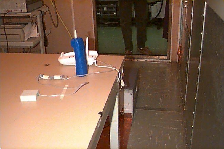
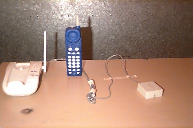
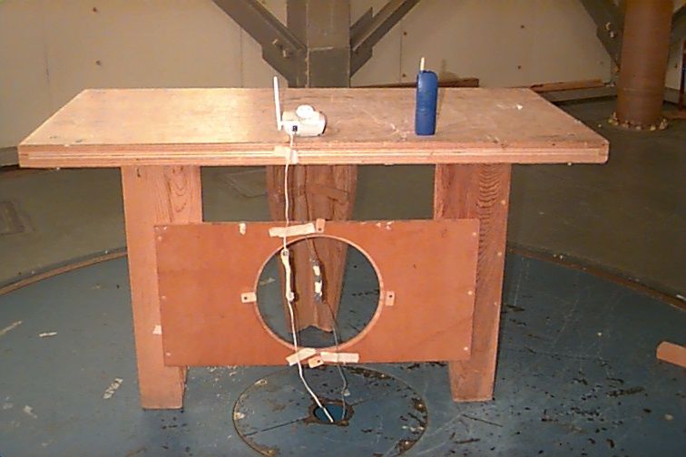
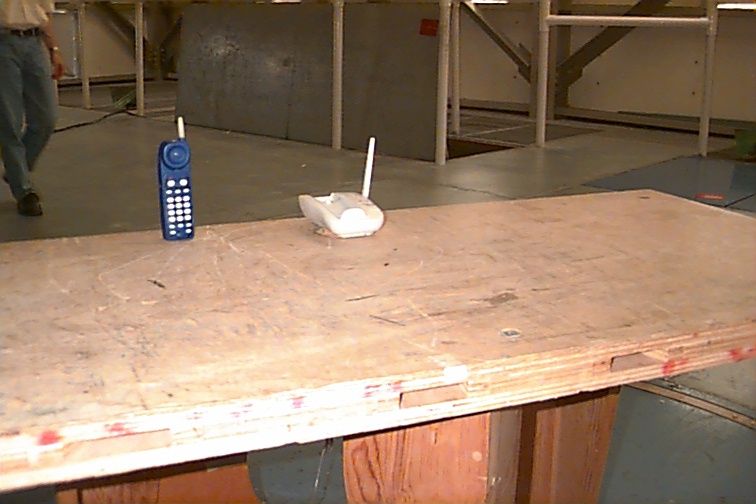
This test data is not necessarily indicative of a product's conformance to a particular standard or EC directive unless taken in the context of a formal Global Product Compliance Laboratory test report and signed by an authorized Global Product Compliance Laboratory reviewer. 1.1 Radiated Emissions OATS Name of EUT: 8500 Cordless Telephone Serial Number:Date of Test: Sept. 11, 1998 Temperature: 22°C Relative Humidity: 55% Product Class: BTest Facility:Open Area Test Site Test Specification:CFR 47, Part 15Measurement Distance: 3 Meters File Number: 98083Test Engineer: T. Donnelly Freq. (MHz) EUT Azimuth (Degrees) Antenna Height (cm) Antenna Polarity (H/V) Meter Reading (dBuV) Cable Loss (dB) Antenna Factor (dB/m) Ambient Level (dBuV/m) Field Intensity (dBuV/m) S p e c Limit (dBuV/m) Margin (dB) 52.50 129.0 202 V 5.0 1.8 10.4 0* 17.3 40.0 22.7 62.62 360.0 143 H 8.1 2.0 9.1 0* 19.2 40.0 20.8 62.62 216.6 131 V 7.0 2.0 9.1 0* 18.1 40.0 21.9 75.01 60.0 305 V 8.6 2.2 8.0 0* 18.7 40.0 21.3 141.01360.0 135 H 11.2 2.9 12.8 0* 26.9 43.5 16.6 173.02 0.0 100 H 8.6 3.2 12.3 0* 24.1 43.5 19.4 185.02358.2 166 H 2.7 3.3 12.8 0* 18.7 43.5 24.8 This test data is not necessarily indicative of a product's conformance to a particular standard or EC directive unless taken in the context of a formal Global Product Compliance Laboratory test report and signed by an authorized Global Product Compliance Laboratory reviewer. Name of EUT: 8500 Cordless Telephone Serial Number:Date of Test: Sept. 11, 1998 Temperature: 22°C Relative Humidity: 55% Product Class: BTest Facility:Open Area Test Site Test Specification:CFR 47, Part 15Measurement Distance: 3 Meters File Number: 98083Test Engineer: T. Donnelly Radiated Emissions 0. 0 10 .0 20 .0 30 .0 40 .0 50 .0 60 .0 70 .0 80 .0 10.0 100.0 1000.0 Frequency (MHz) Field Strength (dBuV/m) This test data is not necessarily indicative of a product's conformance to a particular standard or EC directive unless taken in the context of a formal Global Product Compliance Laboratory test report and signed by an authorized Global Product Compliance Laboratory reviewer. 1.2 Radiated Emissions OATS Name of EUT: 8500 Cordless Telephone Serial Number:Date of Test: Sept. 11, 1998 Temperature: 22°C Relative Humidity: 55% Product Class: BTest Facility:Open Area Test Site Test Specification:CFR 47, Part 15Measurement Distance: 3 Meters File Number: 98083Test Engineer: T. Donnelly Freq. (MHz) EUT Azimuth (Degrees) Antenna Height (cm) Antenna Polarity (H/V) Meter Reading (dBuV) Cable Loss (dB) Antenna Factor (dB/m) Ambient Level (dBuV/m) Field Intensity (dBuV/m) S p e c Limit (dBuV/m) Margin (dB) 902.40162.6 194 H 52.6 6.5 26.3 0* 85.4 94.0 8.6 902.40231.6 100 V 58.1 6.5 26.3 0* 90.9 94.0 3.1 903.55 93.0 100 V 60.5 6.6 26.3 0* 93.3 94.0 0.7 903.55177.6 100 H 53.3 6.6 26.3 0* 86.1 94.0 7.9 904.83180.0 100 H 52.5 6.6 26.3 0* 85.4 94.0 8.6 904.83342.6 100 V 60.3 6.6 26.3 0* 93.2 94.0 0.8 924.93315.0 179 V 58.0 6.7 26.7 0* 91.4 94.0 2.6 924.93 58.8 158 H 56.2 6.7 26.7 0* 89.6 94.0 4.4 926.08332.4 100 V 57.1 6.7 26.7 0* 90.5 94.0 3.5 926.08 57.0 100 H 53.8 6.7 26.7 0* 87.2 94.0 6.8 927.36 66.6 161 H 54.2 6.7 26.8 0* 87.6 94.0 6.4 927.36339.0 100 V 56.7 6.7 26.8 0* 90.1 94.0 3.9 This test data is not necessarily indicative of a product's conformance to a particular standard or EC directive unless taken in the context of a formal Global Product Compliance Laboratory test report and signed by an authorized Global Product Compliance Laboratory reviewer. Name of EUT: 8500 Cordless Telephone Serial Number:Date of Test: Sept. 11, 1998 Temperature: 22°C Relative Humidity: 55% Product Class: BTest Facility:Open Area Test Site Test Specification:CFR 47, Part 15Measurement Distance: 3 Meters File Number: 98083Test Engineer: T. Donnelly Radiated Emissions 0. 0 10 .0 20 .0 30 .0 40 .0 50 .0 60 .0 70 .0 80 .0 90 .0 10 0.0 11 0.0 12 0.0 900.0905.0910.0915.0920.0925.0930.0935.0940.0 Frequency (MHz) Field Strength (dBuV/m) This test data is not necessarily indicative of a product's conformance to a particular standard or EC directive unless taken in the context of a formal Global Product Compliance Laboratory test report and signed by an authorized Global Product Compliance Laboratory reviewer. 1.3 Radiated Emissions OATS Name of EUT: 8500 Cordless Telephone Serial Number:Date of Test: Sept. 11, 1998 Temperature: 22°C Relative Humidity: 55% Product Class: BTest Facility:Open Area Test Site Test Specification:CFR 47, Part 15Measurement Distance: 3 Meters File Number: 98083Test Engineer: T. Donnelly Freq. (MHz) EUT Azimuth (Degrees) Antenna Height (cm) Antenna Polarity (H/V) Meter Reading (dBuV) Cable Loss (dB) Antenna Factor (dB/m) Ambient Level (dBuV/m) Field Intensity (dBuV/m) S p e c Limit (dBuV/m) Margin (dB) Channel 1, Handset 1808.0 33.0 156.0V11.00.027.00*38.05416.0 1808.0 316.0 268.0H8.00.027.00*35.05419.0 2714.0 329.0 268.0H14.00.029.00*43.05411.0 2714.0 153.0 324.0V10.00.029.00*39.05415.0 3621.0 166.0 126.0H7.00.031.30*38.35415.7 Channel 1, Base 1850.0 12.0 149.0V11.00.027.20*38.254.015.8 2775.0 164.0 126.0V14.00.029.20*43.254.010.8 2775.0 344.0 302.0H11.00.029.20*40.254.013.8 Channel 10, Handset 1890.0 148.0 149.0H15.00.027.40*42.454.011.6 1890.0 106.0 122.0V22.00.027.40*49.454.04.6 2711.0 358.0 141.0V23.00.029.00*52.054.02.0 2711.0 224.0 149.0H19.00.029.00*48.054.06.0 Channel 10, Base 1854.0 333.0 152.0V10.00.027.20*37.254.016.8 2711.03.0 282.0V18.00.029.00*47.054.07.0 2711.0 145.0 100.0H20.00.029.00*49.054.05.0 3709.0 98.0 152.0V15.00.031.80*46.854.07.2 4631.0 26.0 100.0V15.00.032.20*47.254.06.8 Channel 20, Handset 1806.0 356.0 152.0H12.00.027.00*39.054.015.0 1806.0 108.0 156.0V22.00.027.00*49.054.05.0 2710.00.0 202.0V23.00.029.00*52.054.02.0 2710.0 189.0 133.0H19.00.029.00*48.054.06.0 Channel 20, Base 1856.0 99.0 227.0H10.00.027.20*37.254.016.8 1856.0 239.0 180.0V13.00.027.20*40.254.013.8 2716.0 323.0 269.0V13.00.029.00*42.054.012.0 2716.0 359.0 268.0H12.00.029.00*41.054.013.0 3713.07.0 100.0H11.00.031.…
Text truncated - open the document above for the full version.
Test Report
This test data is not necessarily indicative of a product's conformance to a particular standard or EC directive unless taken in the context of a formal Global Product Compliance Laboratory test report and signed by an authorized Global Product Compliance Laboratory reviewer. Subject: Correspondence ID 4058 Date: July 13, 2001 FCC ID: NRM93 From: Cayetano Chavez To: Federal Communications Commission Equipment Authorization Branch 7435 Oakland Mills Road Columbia, MD 21046 To whom it may concern: The following is part of the Information Requested by Correspondence ID 4058. The items covered by this part of the report are 3 and 4. Please notice the type of detector used is in the end of each page, also the results reported for strength of 3 channels are included in page 6. Sincerely Cayetano Chavez This test data is not necessarily indicative of a product's conformance to a particular standard or EC directive unless taken in the context of a formal Global Product Compliance Laboratory test report and signed by an authorized Global Product Compliance Laboratory reviewer. 1.1 Radiated Emissions OATS Name of EUT: 8500 Cordless Telephone Serial Number:Date of Test: Sept. 11, 1998 Temperature: 22°C Relative Humidity: 55% Product Class: BTest Facility:Open Area Test Site Test Specification:CFR 47, Part 15Measurement Distance: 3 Meters File Number: 98083Test Engineer: T. Donnelly Freq. (MHz) EUT Azimuth (Degrees ) Antenna Height (cm) Antenn a Polarity (H/V) Meter Reading (dBuV) Cable Loss (dB) Antenna Factor (dB/m) Ambient Level (dBuV/m ) Field Intensity (dBuV/m) Spec Limit (dBuV/m ) Margin (dB) 52.50 129.0 202 V 5.0 1.8 10.4 0* 17.3 40.0 22.7 62.62 360.0 143 H 8.1 2.0 9.1 0* 19.2 40.0 20.8 62.62 216.6 131 V 7.0 2.0 9.1 0* 18.1 40.0 21.9 75.01 60.0 305 V 8.6 2.2 8.0 0* 18.7 40.0 21.3 141.01360.0 135 H 11.2 2.9 12.8 0* 26.9 43.5 16.6 173.02 0.0 100 H 8.6 3.2 12.3 0* 24.1 43.5 19.4 185.02358.2 166 H 2.7 3.3 12.8 0* 18.7 43.5 24.8 1. The data in the above table was measured with an Electro-Metrics EMC-60 utilizing and quali-peak detector and a 1MHz Bandwidth. This test data is not necessarily indicative of a product's conformance to a particular standard or EC directive unless taken in the context of a formal Global Product Compliance Laboratory test report and signed by an authorized Global Product Compliance Laboratory reviewer. Name of EUT: 8500 Cordless Telephone Serial Number:Date of Test: Sept. 11, 1998 Temperature: 22°C Relative Humidity: 55% Product Class: BTest Facility:Open Area Test Site Test Specification:CFR 47, Part 15Measurement Distance: 3 Meters File Number: 98083Test Engineer: T. Donnelly Radiated Emissions 0.0 10.0 20.0 30.0 40.0 50.0 60.0 70.0 80.0 10.0 100.0 1000.0 Frequency (MHz) Field Strength (dBuV/m) 1. The data in the above table was measured with an Electro-Metrics EMC-60 utilizing and average detector and a 1MHz Bandwidth. This test data is not necessarily indicative of a product's conformance to a particular standard or EC directive unless taken in the context of a formal Global Product Compliance Laboratory test report and signed by an authorized Global Product Compliance Laboratory reviewer. 1.2 Radiated Emissions OATS Name of EUT: 8500 Cordless Telephone Serial Number:Date of Test: Sept. 11, 1998 Temperature: 22°C Relative Humidity: 55% Product Class: BTest Facility:Open Area Test Site Test Specification:CFR 47, Part 15Measurement Distance: 3 Meters File Number: 98083Test Engineer: T. Donnelly Freq. (MHz) EUT Azimuth (Degrees ) Antenna Height (cm) Antenn a Polarity (H/V) Meter Reading (dBuV) Cable Loss (dB) Antenna Factor (dB/m) Ambient Level (dBuV/m ) Field Intensity (dBuV/m) Spec Limit (dBuV/m ) Margin (dB) 902.40162.6 194 H 52.6 6.5 26.3 0* 85.4 94.0 8.6 902.40231.6 100 V 58.1 6.5 26.3 0* 90.9 94.0 3.1 903.55 93.0 100 V 60.5 6.6 26.3 0* 93.3 94.0 0.7 903.55177.6 100 H 53.3 6.6 26.3 0* 86.1 94.0 7.9 904.83180.0 100 H 52.5 6.6 26.3 0* 85.4 94.0 8.6 904.83342.6 100 V 60.3 6.6 26.3 0* 93.2 94.0 0.8 924.93315.0 179 V 58.0 6.7 26.7 0* 91.4 94.0 2.6 924.93 58.8 158 H 56.2 6.7 26.7 0* 89.6 94.0 4.4 926.08332.4 100 V 57.1 6.7 26.7 0* 90.5 94.0 3.5 926.08 57.0 100 H 53.8 6.7 26.7 0* 87.2 94.0 6.8 927.36 66.6 161 H 54.2 6.7 26.8 0* 87.6 94.0 6.4 927.36339.0 100 V 56.7 6.7 26.8 0* 90.1 94.0 3.9 1. The measured data in the table above was taken using a Polarad (R&S) test receiver utilizing an average detector. This test data is not necessarily indicative of a product's conformance to a particular standard or EC directive unless taken in the context of a formal Global Product Compliance Laboratory test report and signed by an authorized Global Product Compliance Laboratory reviewer. Name of EUT: 8500 Cordless Telephone Serial Number:Date of Test: Sept. 11, 1998 Temperature: 22°C Relative Humidity: 55% Product Class: BTest Facility:Open Area Test Site Test Specification:CFR 47, Part 15Measurement Distance: 3 Meters File Number: 98083Test Engineer: T. Donnelly Radiated Emissions 0.0 10.0 20.0 30.0 40.0 50.0 60.0 70.0 80.0 90.0 100.0 110.0 120.0 900.0905.0910.0915.0920.0925.0930.0935.0940.0 Frequency (MHz) Field Strength (dBuV/m) 1. The measured data in the table above was taken using a Polarad (R&S) test receiver utilizing an average detector. This test data is not necessarily indicative of a product's conformance to a particular standard or EC directive unless taken in the context of a formal Global Product Compliance Laboratory test report and signed by an authorized Global Product Compliance Laboratory reviewer. 1.3 Radiated Emissions OATS Name of EUT: 8500 Cordless Telephone Serial Number:Date of Test: Sept. 11, 1998 Temperature: 22°C Relative Humidity: 55% Product Class: BTest Facility:Open Area Test Site Test Specification:CFR 47, Part 15Measurement Distance: 3 Meters File Number: 98083Test Engineer: T. Donnelly Freq. (MHz) EUT Azimuth (Degrees ) Antenna Height (cm) Antenn a Polarity (H/V) Meter Reading (dBuV) Cable Loss (dB) Antenna Factor (dB/m) Ambient Level (dBuV/m ) Fie…
Text truncated - open the document above for the full version.
Test Report
1.1 Radiated Emissions OATS Name of EUT: Phillips C. C. 900 MHz Phone Serial Number:Date of Test: 11-21-98 Temperature: 22°CRelative Humidity:33% Product Class:Test Facility:Open Area Test Site Test Specification: FCC CFR 47Measurement Distance:3 m File Number:98600Test Engineer: GM Freq. (MHz) EUT Azimuth (Degrees ) Antenna Height (cm) Antenn a Polarity (H/V) Meter Reading (dBuV) Cable Loss (dB) Antenna Factor (dB/m) Ambient Level (dBuV/m ) Field Intensity (dBuV/m) Spec Limit (dBuV/m ) Margin (dB) 902.40112.8 141 V 57.7 6.5 27.7 0* 91.9 94.0 2.1 902.40166.8 219 H 51.5 6.5 27.7 0* 85.7 94.0 8.3 903.55 27.6 156 H 47.5 6.6 27.7 0* 81.8 94.0 12.2 903.55 93.6 147 V 56.2 6.6 27.7 0* 90.5 94.0 3.5 904.83160.8 157 V 53.4 6.6 27.7 0* 87.7 94.0 6.3 904.83 30.6 156 H 47.1 6.6 27.7 0* 81.4 94.0 12.6 924.93 93.6 100 H 57.5 6.7 28.3 0* 92.5 94.0 1.5 924.93147.0 175 V 53.6 6.7 28.3 0* 88.6 94.0 5.4 926.08143.4 176 V 52.2 6.7 28.3 0* 87.2 94.0 6.8 926.08317.4 100 H 55.7 6.7 28.3 0* 90.7 94.0 3.3 927.36 80.4 100 H 54.8 6.7 28.4 0* 89.8 94.0 4.2 927.36153.0 169 V 49.9 6.7 28.4 0* 84.9 94.0 9.1 The measured data in the table above was taken using a Polarad (R&S) test receiver utilizing a Quasipeak detector. Name of EUT: Phillips C. C. 900 MHz Phone Serial Number:Date of Test: 11-21-98 Temperature: 22°CRelative Humidity:33% Product Class:Test Facility:Open Area Test Site Test Specification: FCC CFR 47Measurement Distance:3 m File Number:98600Test Engineer: GM Radiated Emissions 0.0 10.0 20.0 30.0 40.0 50.0 60.0 70.0 80.0 90.0 100.0 900.0905.0910.0915.0920.0925.0930.0 Frequency (MHz) Field Strength (dBuV/m) The measured data in the table above was taken using a Polarad (R&S) test receiver utilizing a Quasipeak detector. *RBW100kHzVBW100kHzSWP50.0ms STOP927.860MHzSTART926.860MHz RL60.5dBV *ATTEN0dB 5dB/ MKR54.92dBV 927.360MHz D This is the highest frequency handled by the equipment under test, and is being used by the base. The frequency correspond to the last channel the equipment is using and the frequency carrier is of 927.36 MHz. *RBW100kHzVBW100kHzSWP50.0ms …
Text truncated - open the document above for the full version.
Contact Information
Applicant
Yaron Oren-Pines
732-544-3174Fax: 732-544-2956
Technical Contact
Philips Consumer CommunicationsCayetano Chavez
[email protected]732-544-3264
246 Industrial Way West (Rm E123) · Eatontown, New Jersey · United States
Non-Technical Contact
Philips Consumer CommunicationStephen R Whitesell
swhitesell@@pcc.lucent.com732-544-3017
Technical Specifications
| # | Rule Parts | Frequency Range | Power Output |
|---|---|---|---|
| 2 | 15C | 924.928 MHz - 927.36 MHz | - |
Other Applications from Philips Consumer Communications
NRM900LUCENT
Aug 24, 1999900 MHz Wireless Intercom
Equipment Class
DXT - Part 15 Low Power Transceiver, Rx Verified
NRMTCA620-1B
Sep 02, 1998TNE - Licensed Non-Broadcast Transmitter Held to Ear
Equipment Class
TNE - Licensed Non-Broadcast Transmitter Held to EarNRMTCA620-11
Apr 26, 1998TNE - Licensed Non-Broadcast Transmitter Held to Ear
Equipment Class
TNE - Licensed Non-Broadcast Transmitter Held to Ear