NS2MH9006900MHz Cordless Phone
Guangdong (Bao An) Communication Co. Ltd.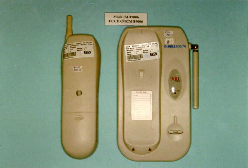
Click to zoom
Application Details
- Equipment Class
- DXT - Part 15 Low Power Transceiver, Rx Verified
- Date of Grant
- Nov 11, 1998
- Application Purpose
- Original Equipment
- Date of Application
- Oct 18, 1998
- Equipment Note
- 900MHz Cordless Phone
- Frequency Range
- 926.12000000 - 927.29000000
- Country
- China
Documents & Files
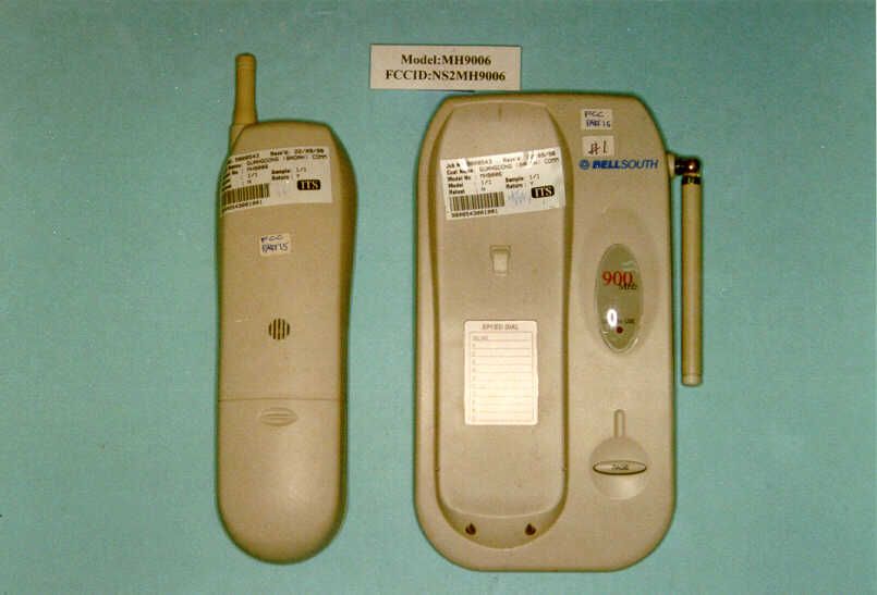
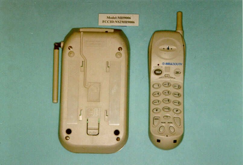
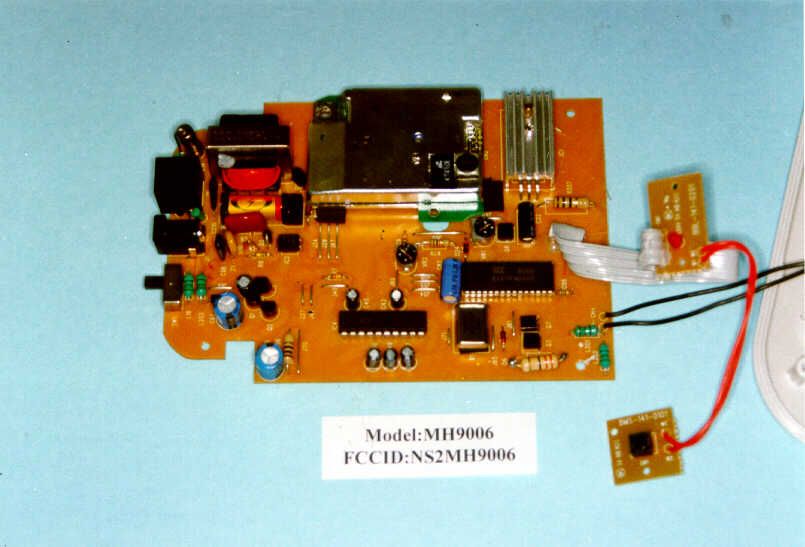
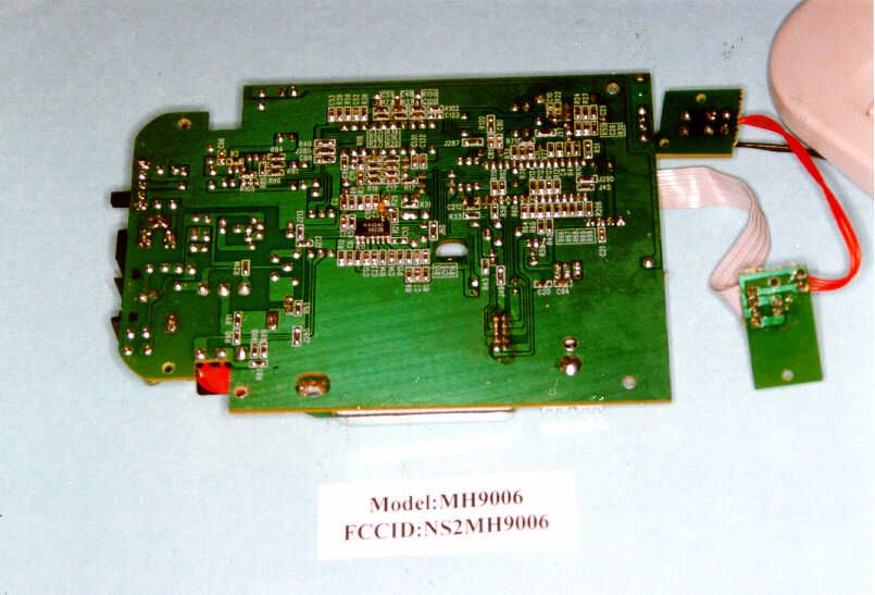
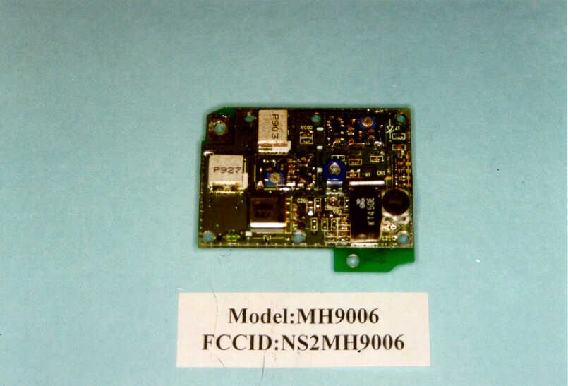
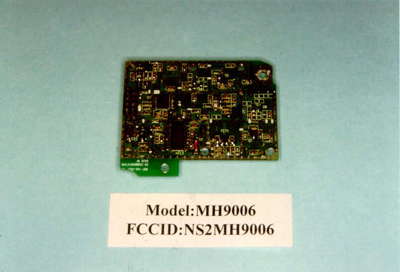
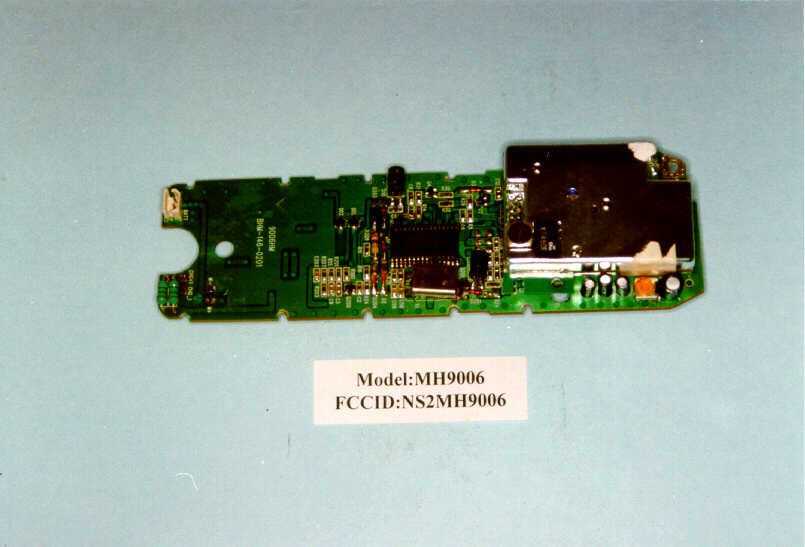
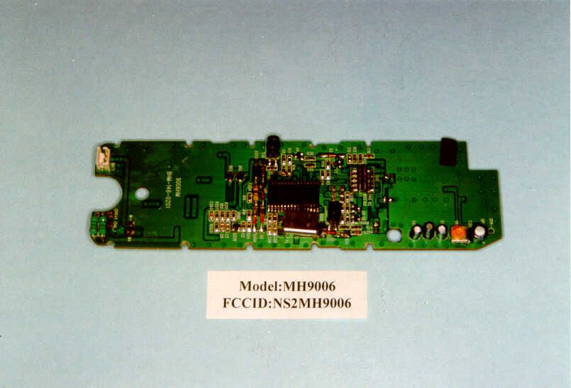
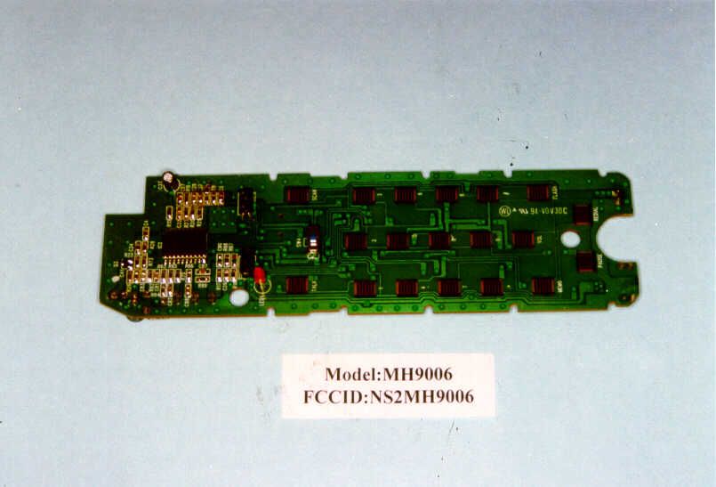
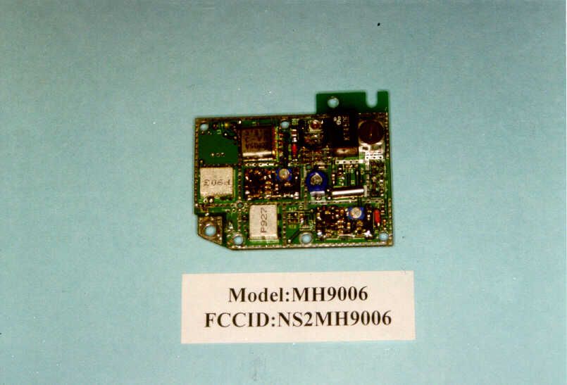
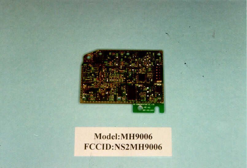
Document Text
Text extracted from the exhibit documents filed with the FCC. Open a document above to read the original.
Block Diagram
DRAWN BY DATE : PAGE : REVISION : CHECKED BY CHECKED BY APPROVED BY TITLE : CHECKED BY CHECKED BY TITLE : GD (BAOAN) COMMUNICATION CO., LTD. MODULAR JACK J2 RF AMPIFIER Q5 TX POWER RF AMP Q1 MIXER FET1 10.7 MHz FL1 450 KHz FILTER FL2 IF DETECTOR KA3361 SML-101 HYB1 RELAY RL1 CPU IC3 REGULATOR IC1 1N4004 D11 DC JACK J1 6V 9V 9VDC LED2 CHARGE/INUSE CHANNEL CONTROL CPU CLOCK DTMF RESISTOR LADDER ANTENNA RX VCO Q7, L5 LOW PASS FILTER PLL IC1 11.150MHz X1 RX DATA U1B,U1A TX DATA LOW PASS FILTER TX VCO Q1,M1 COMPRESSOR IC4 TX POWER CONTROL Q8 PULSE TONE SW1 VCC 6V 6V CARRIER DETECTOR TX MUTE R X M U T E VCC EXPANDER IC4 9V AUDIO BUFFER Q2, Q9 RELAY DRIVER Q10 CHARGE DETECT Q7 RINGER DETECT IC2 9V CHG (+) CHG (-) VCC MH9006 (900MHz) BASE BLOCK DIAGRAM DAN CORONIA Sept 14,`98 1 OF 1 A RING TIP X1 4.00MHz F2 903MHz F1 927MHz CHECKED TITLE : DRAWN BY CHECKED APPROVED BY DATE : PAGE : REVISION : GD (BAOAN) COMMUNICATION CO., LTD. DATE : PAGE : REVISION : KEY IN / OUT RX POWER ANTENNA Q1 MIXER FET1 10.7MHz FILTER FL1 IF DETECTOR KA3361 EXPANDER IC2A AUDIO AMPLIFIER Q3 TX POWER SPEAKER SPK1 VCC BUZZER BZ1 BUZZER DRIVER Q201 RING OUT RESET DETECTOR Q200 CHARGE DETECTOR + CHARGE TERMINAL 11.150MHz X1 PLL IC IC1 VCC LED1 IN USE VCC RX POWER SWITCH Q105, TX POWER SWITCH Q1 TX POWER CONTROL RX POWER CONTROL DATA AMPLIFIER U1B,U1C VCC TX POWER AMPLIFIER Q5 TX VCO Q1,M1 COMPRESSOR IC2B CONDENSER MIC MIC1 RX VCO Q1,M1 DAN CORONIA 4.00MHz X1 TX POWER TX MUTE C A R R I E R D E T E C T O R R X M U T E R X D A T A 12 3 4 56 7 8 9 0# TALK FLASH SCAN REDIAL PAUSE MEMO 450 KHz FILTER FL2 RF AMPLIFIER CPU IC1 MH9006 (900MHz) HANDSET BLOCK DIAGRAM Sept 14,`98 1 OF 1A 1N4003 D203 - BATT F1 903MHz F2 927MHz VOL * TONE
Operational Description
TITLE : MH9006 Circuit Description (40 Channels Basic Cordless Telephone 900MHz) FI C CIRCUIT DESCRIPTION 1. HANDSET 1.1RECEPTION Figure 1 As shown in figure 1, the received signal from the base unit passes through 927 MHz Filter and amplified by RF Amplifier (Q1). The amplified input signal is mixed with RX VCO (Q1,M2,D1) signal. The VCO oscillation is controlled by error signals from PLL IC (IC1) pin no. 10. The channel information to PLL IC is provided by Microprocessor IC (IC1) pin nos. 25, 26 and 30. (Serial data outputs). The Mixer output from FET1 passes through 10.7 MHz Ceramic Filter (FL1) and enters to FM Demodulator IC (IC2A) pin no. 16. This signal mixes with 11.150 MHz signal from PLL IC pin no. 11, which is connected to IC2 pin no.1. The mixed signal is filtered by 450 KHz Filter (FL2). Q1 FET1 FL1 FL2 L7 3 5 8 1 9 RX VCO Local Oscillator Audio Output ANTENNA L3 M3 IC2 C 9 IC1 9 IC1 R 31 1.2RINGER OUTPUT D201 Q201 BUZZER RX DATA Amplifier B+ Figure 2 U1C, U1B TITLE : MH9006 Circuit Description (40 Channels Basic Cordless Telephone 900MHz) SPEAKER R 16 9 IC1 IC2A 19 After detection of ring signal, the base unit will transmit the data code signal including security code to handset. As shown in figure 2, the demodulated ring signal from pin no. 9 of FM Demodulator IC1 is fed to low pass filter and amplified by RX Data Amplifier and its output is connected to RX Data port of Microprocessor IC (IC1). The ring signal output from pin no. 9 of Microprocessor IC (IC1) goes to buzzer driver Q201 to activate the buzzer. 1.3VOICE OUTPUT Figure 3 The demodulated signal, resulting from Double Super Heterodyne system, which appears at output pin no. 9 of IC1 is connected to pin no. 16 Expander input of Compander IC (IC2A) for expansion. The expanded audio output from IC2A pin no. 19 is finally amplified by Q3 and A.C. coupled to the receiver unit with Hearing Aid Compatibility (HAC). C Q3 C R C TX B+ IC1 pin 3 CP1 Q5 C C R D4 R R C 28 IC1 1.4DATA TRANSMISSION C Q1 L3 COIL ANTENNA TX B+ IC1 pin 1 FIN Figure 4 F2 M9 M2 TITLE : MH9006 Circuit Description (40 Channels Basic Cordless Telephone 900MHz) MODULATOR As shown in figure 4, the TX data code output including security code from IC1 pin no. 28 is connected to TX VCO for modulation. The data code signal is modulated with the carrier frequency generated by the RFoscillator (Q1). The oscillator frequency is controlled by the error signal from pin no.3 of PLL IC (IC1). The modulated signal is amplified by RF amplifier stage (Q5) and then passes through 927MHz filter stage (F2). The FM modulated signal is radiated by the handset Rubberized Antenna. 1.5 VOICE TRANSMISSION Figure 5 Voice signal from condenser mic is coupled to pin no. 8 of Compander IC (IC2B). The voice signal is compressed by IC2B and then connected to TX VCO stage for modulation. 1.6RECEIVER POWER CONTROL • When at STANDBY mode and RING ON mode the handset has 50 ms power on and 800ms power off on receiver section. • When at STANDBY mode and SAVE ON mode, the handset have no power on receiver section. • The power saving is controlled by Microprocessor IC (IC1) pin no. 18 (RX power control) and Q1. 1.7TRANSMIT POWER CONTROL • When at TALK mode, the handset transmitter should be working. • The transmitter power is controlled by Microprocessor IC (IC1) pin no. 17 (TX power control) and Q6. C R TX B+ MIC1 CONDENSER MIC 8 1 IC2B R R C C TITLE : MH9006 Circuit Description (40 Channels Basic Cordless Telephone 900MHz) R R C R R R R R R C C D IC2 KA33610 10 13 12 13 9 11 IC101 CPU RX B+ C C Figure 7 1.8 BATTERY LOW DETECTOR •When the battery voltage goes down until 3.3 to 0.1 Vdc, the LED1 will flash with warning sound “Bi, Bi”. 1.9 BATTERY CHARGING Figure 6 •When the handset is placed on the base unit cradle, the battery will be charging and will be detected by Microprocessor IC (IC1) pin no.15. •Microprocessor IC will exchange security code randomly. 1.10 SQUELCH VCC CHG + CHG - R R R D206 1N4148 BATT1 3.6V L200 L201 15 IC1 C D204 D207 1N4148 TITLE : MH9006 Circuit Description (40 Channels Basic Cordless Telephone 900MHz) As shown in figure 7, the audio output (noise output) from FM Demodulator IC (IC1) pin no.9 goes to pin no. 10 (Noise filter input) and the output from pin no. 11 will enter to pin no. 12 to activate the squelch control of IC1. The output from pin no. 13 is connected to the Microprocessor IC (IC1) for RSSI Detection. NOTE : • When the handset is far away from the base unit, squelch circuit of IC1 operates and pin no. 13 of IC1 goes ‘HI’. This will be detected by Microprocessor and after 10 seconds, it goes to standby mode. 2. BASE UNIT 2.1RECEPTION Base receiver circuit is similar to handset receiver circuit description as shown in figure 1. The difference with section 1.1 are local frequency and receiving frequency as descibe below. The received signal from the handset unit passes through 927 MHz filter and amplified by RF RF Amplifier (Q1). The amplified signal is mixed with RX VCO (Q1,M2, D1). The mixer output from FET1 passes through 10.7 MHz filter and enters to FM Demodulator IC (IC2) pin no. 16. This signal is mixed with 11.150 MHz signal from PLL IC (IC1) pin no.9, which is connected to IC2 pin no. 1. The mixed signal is filtered by 450 KHz Filter (FL2). 2.2DATA INPUT The demodulated data code from FM Demodulator IC (IC2) pin no. 9 is fed to Lowpass filter and its output is connected to code input of Microprocessor IC (IC1). 2.3AUDIO OUTPUT As shown in figure 8, the demodulated signal which appears at output pin of FM Demodulator IC (IC2) pin no. 9 is sent through lowpass filter to Compander IC (IC2A) pin no. 16 (Expander input) for expansion. The expanded audio signal output from IC2A pin no. 19 is coupled to Buffer Amplifier (Q2,Q9) during the CONVERSATION mode. The audio is sent to telephone line via Hybrid X’former (HYB1). TITLE : MH9006 Circuit Description (40 Channels Basic Cordless Telephone 900MHz) TEL. LINE Figure 8 2.4DATA TRANSMISSION Refer to f…
Text truncated - open the document above for the full version.
Test Report
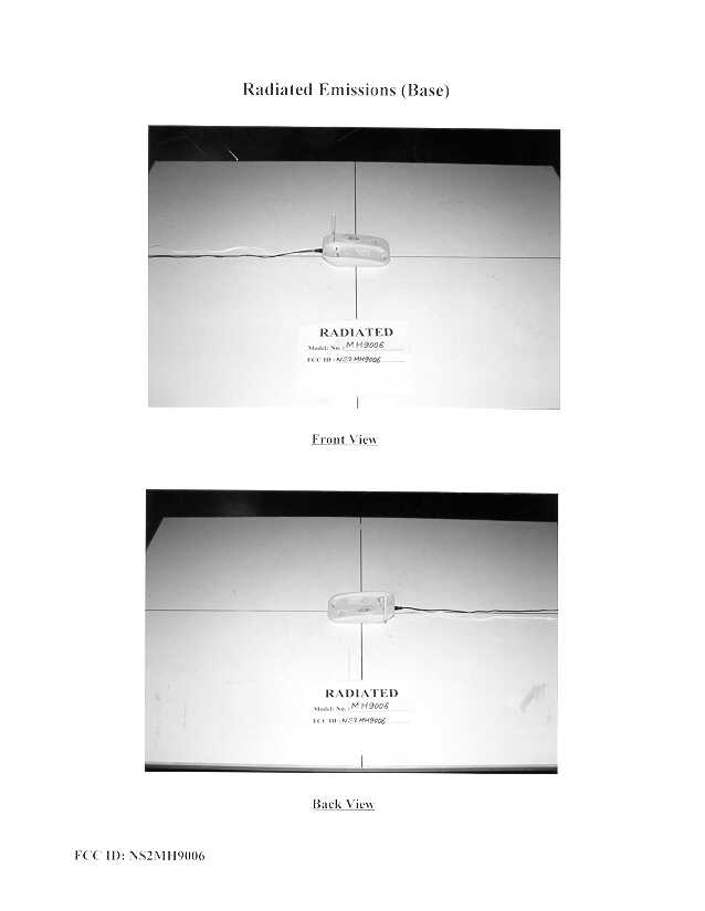
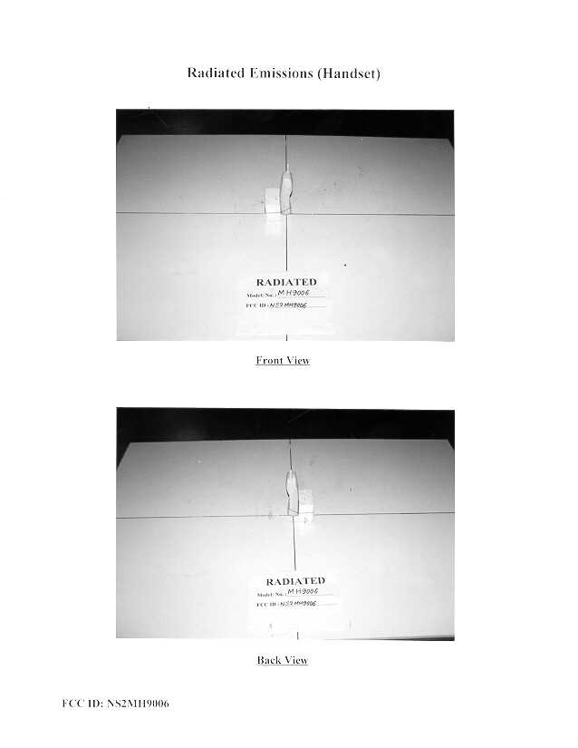
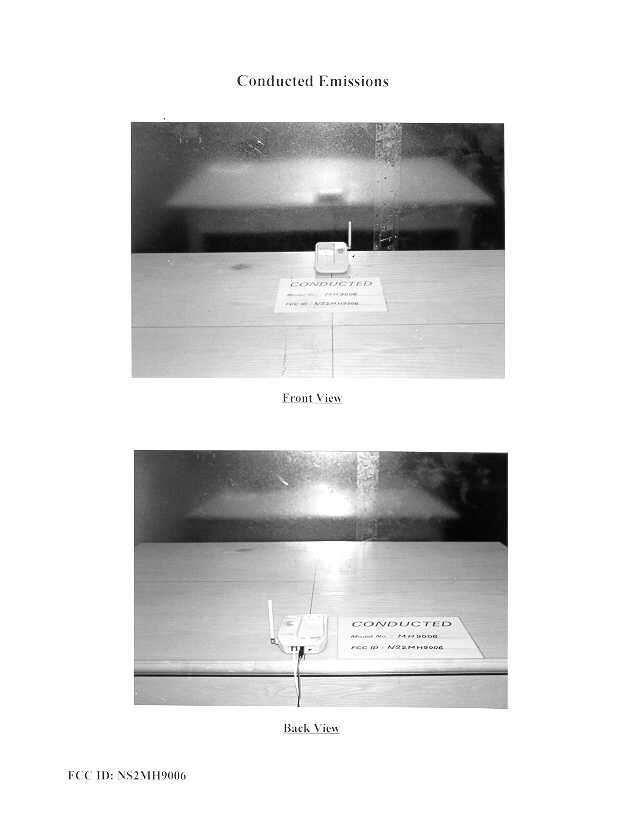
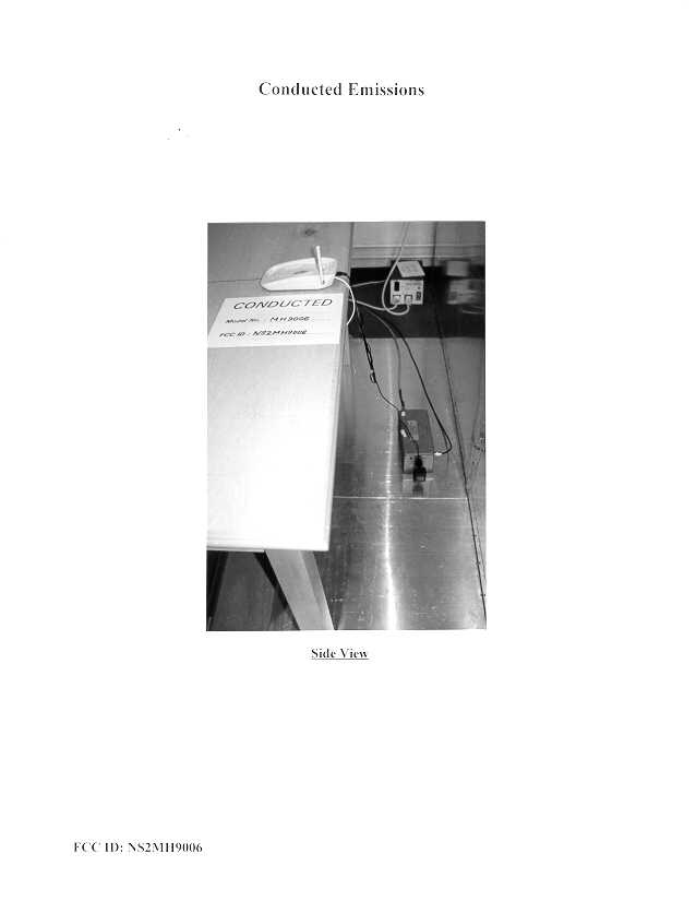
• The test results reported in this report shall refer only to the sample actually tested and shall not refer or be deemed to refer to bulk from which such a sample may be said to have been obtained. • This report shall not be reproduced except in full without prior authorization form Intertek Testing Services Limited FCC ID: NS2MH9006 Guangdong (Baoan) Communication Co., Ltd. Application For Certification 900MHz Cordless Telephone (FCC ID: NS2MH9006) WO# 9808543 CKL/at October 19, 1998 INTERTEK TESTING SERVICES FCC ID: NS2MH9006 i LIST OF EXHIBITS INTRODUCTION EXHIBIT 1:General Description EXHIBIT 2:System Test Configuration EXHIBIT 3:Emission Results EXHIBIT 4:Equipment Photographs EXHIBIT 5:Product Labelling EXHIBIT 6:Technical Specifications EXHIBIT 7:Instruction Manual EXHIBIT 8:Security Code Information INTERTEK TESTING SERVICES FCC ID: NS2MH9006 ii MEASUREMENT/TECHNICAL REPORT Guangdong (Baoan) Communication Co., Ltd. - MODEL: Bellsouth MH9006 FCC ID: NS2MH9006 This report concerns (check one:)Original Grant X Class II Change Equipment Type: Low Power Transmitter (example: computer, modem, transmitter, etc.) Deferred grant requested per 47 CFR 0.457(d)(1)(ii)?Yes No X If yes, defer until : date Company Name agrees to notify the Commission by: date of the intended date of announcement of the product so that the grant can be issued on that date. Transition Rules Request per 15.37?Yes No X If no, assumed Part 15, Subpart C for intentional radiator - the new 47 CFR [10-1-96 Edition] provision. Report prepared by:C. K. Lam Intertek Testing Services. 2/F., Garment Centre, 576 Castle Peak Road, Kowloon, Hong Kong. Phone:852-2746-8211 Fax:852-2785-5487 INTERTEK TESTING SERVICES FCC ID: NS2MH9006 iii Table of Contents 1.0 General Description ................................................................................................................. 2 1.1 Product Description.............................................................................................................. 2 1.2 Related Submittal(s) Grants .................................................................................................3 1.3 Test Methodology ................................................................................................................ 3 1.4 Test Facility.......................................................................................................................... 3 2.0 System Test Configuration ...................................................................................................... 5 2.1 Justification .......................................................................................................................... 5 2.2 EUT Exercising Software.....................................................................................................5 2.3 Support Equipment List and Description.............................................................................. 6 2.4 Equipment Modification ......................................................................................................7 3.0 Emission Results ....................................................................................................................... 9 3.1 Field Strength Calculation ..................................................................................................10 3.2 Radiated Emission Configuration Photograph - Base Unit ................................................. 11 3.3 Radiated Emission Data - Base Unit.......................................................................................12 3.4 Radiated Emission Configuration Photograph - Handset.......................................................18 3.5 Radiated Emission Configuration Data - Handset .............................................................. 19 3.6 Radiated Emission on the bandedge ................................................................................... 23 3.7 Line Conducted Configuration Photograph - Base Unit..................................................... 24 3.8 Line Conducted Data - Base Unit ...........................................................................................25 4.0 Equipment Photographs ........................................................................................................ 28 5.0 Product Labelling ................................................................................................................... 30 6.0 Technical Specifications ......................................................................................................... 32 7.0 Instruction Manual ......................................................................................................................34 8.0 Security Code Information .........................................................................................................36 INTERTEK TESTING SERVICES FCC ID: NS2MH9006 iv List of attached file Exhibit typeFilename Test Reportreport.doc Test Setup Photobase.jpg, handset.jpg, conduct1.jpg, conduct2.jpg External Photoophotot1.jpg, ophoto2.jpg Internal Photoiphoto1.jpg to iphoto9.jpg Block Diagramblock.pdf Schematiccircuit.pdf, RFcircuit.pdf ID Labellabel.pdf ID Locationlocation.pdf User Manualmanual.pdf Test Reportbw.pdf Cover Letterletter.pdf Circuit Descriptiondescri.pdf Test Reportconduct.pdf INTERTEK TESTING SERVICES FCC ID: NS2MH9006 1 EXHIBIT 1 GENERAL DESCRIPTION INTERTEK TESTING SERVICES FCC ID: NS2MH9006 2 1.0 General Description 1.1Product Description The Bellsouth MH9006 is a 900 MHz 40 Channels Analog Modulation Cordless Telephone. The unit is capable of either tone or pulse dialing. The internal power supply's isolation is accomplished through a power transformer having an adequate dielectric rating. The circuit wiring is consistent under the requirement of part 68. The handset unit consists of a keypad with twelve standard keys (0,...9,*,#), 7 function keys (memo, pause, tone, flash, ringer ON…
Text truncated - open the document above for the full version.
Contact Information
Applicant
H. M. Jayantha Perera(Engineering Manager)
867557906455Fax: 86755-790-5962
Technical Contact
Intertek Testing Services Hong Kong Ltd.C.K. Lam
[email protected](852)2746-8211
2/F., Garment Centre, · Kowloon · Hong Kong
Non-Technical Contact
Intertek Testing Services Hong Kong Ltd.C.K. Lam
[email protected](852)2746-8211
Test Firm
Intertek Testing Services Hong KongBilly Chow
Technical Specifications
| # | Rule Parts | Frequency Range | Power Output |
|---|---|---|---|
| 2 | 15C | 926.12 MHz - 927.29 MHz | - |
Other Applications from Guangdong (Bao An) Communication Co. Ltd.
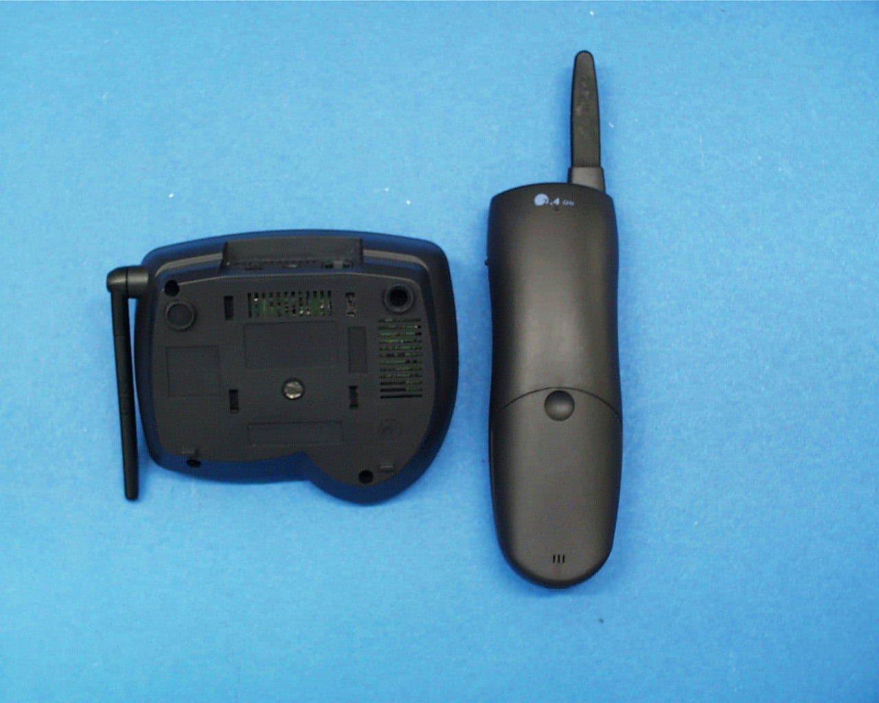
NS2GH9402
Mar 19, 2000Cordless Telephone
Equipment Class
DXX - Part 15 Low Power Communication Device Transmitter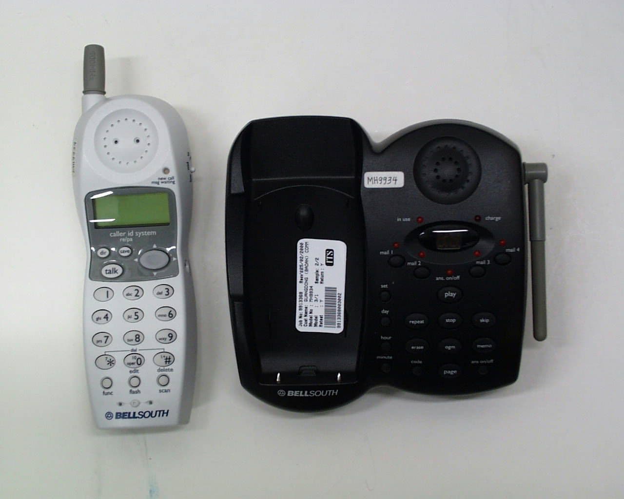
NS2MH9934
Mar 19, 2000Cordless Telephone
Equipment Class
DXX - Part 15 Low Power Communication Device Transmitter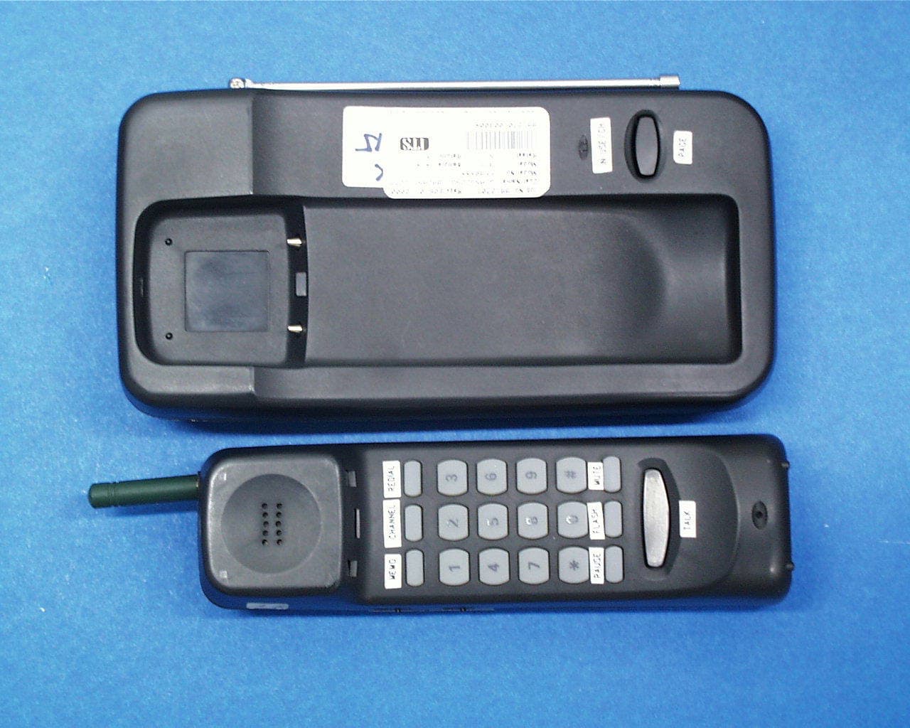
NS2FF905
Mar 07, 2000CORDLESS TELEPHONE
Equipment Class
DXX - Part 15 Low Power Communication Device Transmitter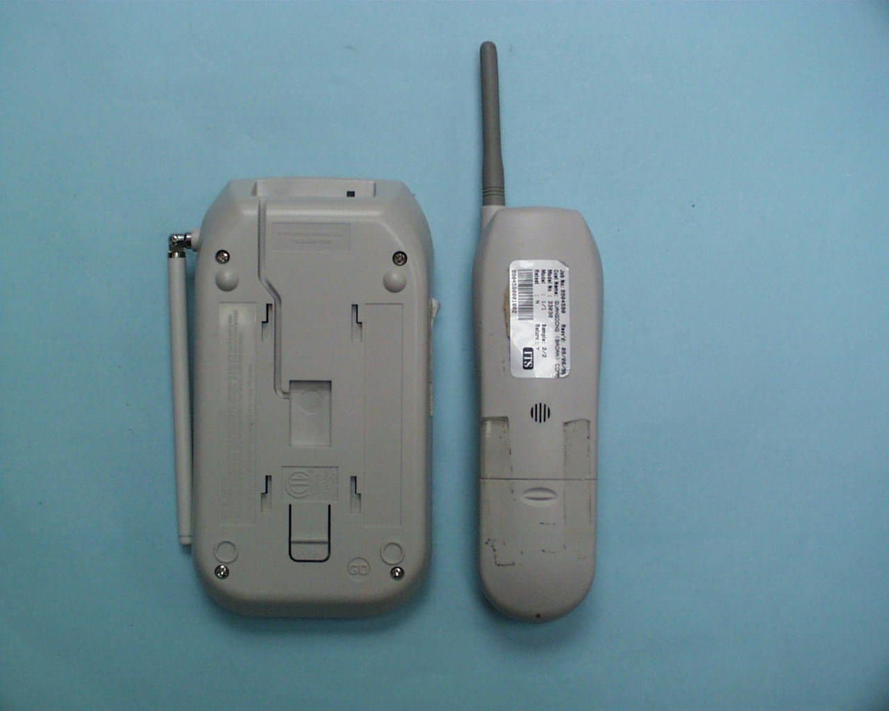
NS233030N
Aug 16, 1999ETS - Part 15 Cordless Telephone System
Equipment Class
ETS - Part 15 Cordless Telephone System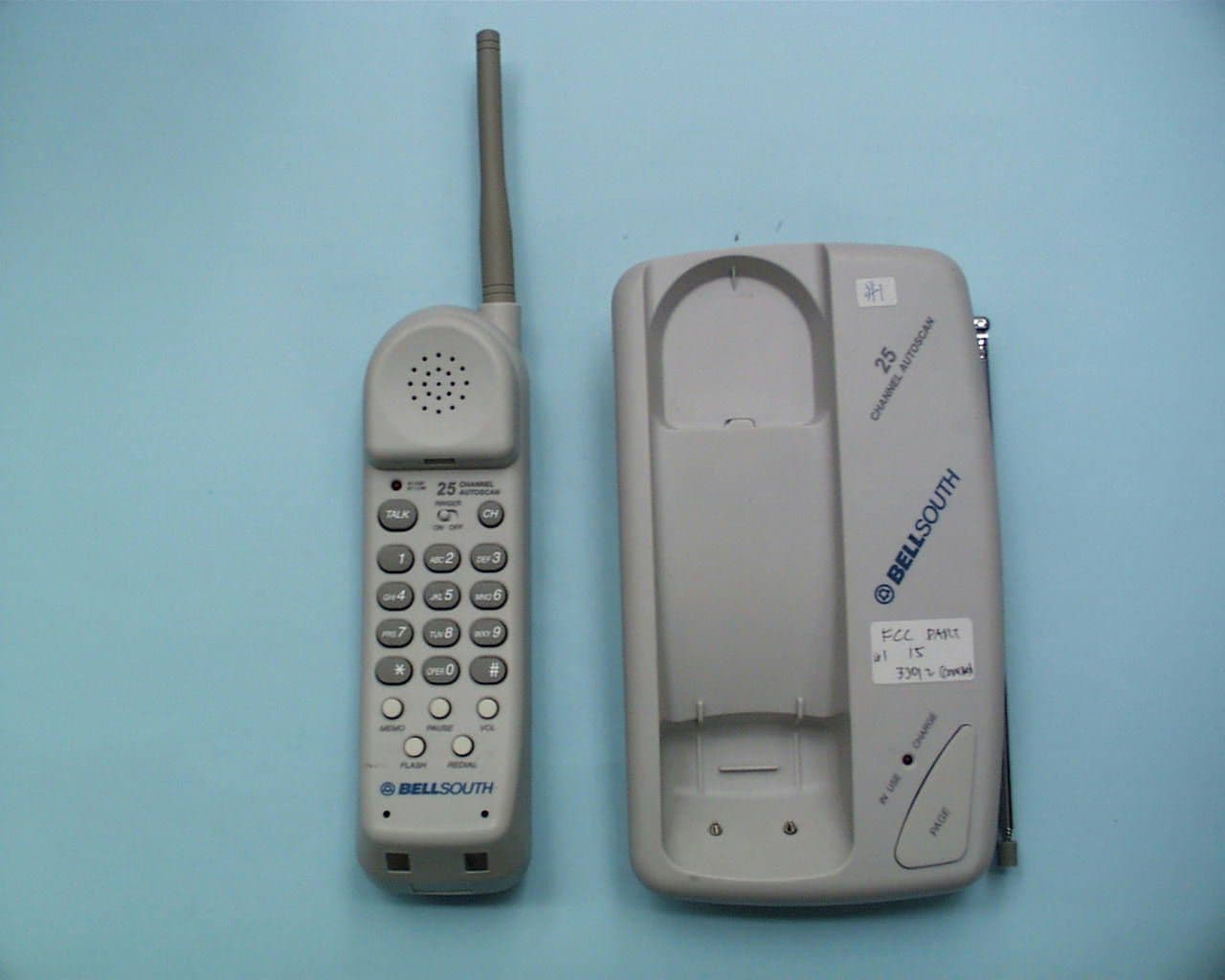
NS233012N
Jul 13, 1999ETS - Part 15 Cordless Telephone System
Equipment Class
ETS - Part 15 Cordless Telephone System