NSBI1000-PIIPersonal Computing Tablet
InnoLabs Corporation
Click to zoom
Application Details
- Equipment Class
- JBC - Part 15 Class B Computing Device/Personal Computer
- Date of Grant
- May 22, 2000
- Application Purpose
- Original Equipment
- Date of Application
- Feb 21, 2000
- Equipment Note
- Personal Computing Tablet
- Company
- InnoLabs Corporation
- Country
- Taiwan
Documents & Files
Document Text
Text extracted from the exhibit documents filed with the FCC. Open a document above to read the original.
Users Manual
Introduction Congratulations. You are the proud new owner of one of the most advanced computing devices on the market today. Getting to know it thoroughly and using it correctly will give you years of reliable, trouble free service. Combining all the speed and functionality of a desktop computer with the mobility of a hand-held device, the Qbe Personal Computing Tablet “in an all in one format” integrates top of the line microprocessors, high capacity storage ( a hard disc that begins at 6 GB) memory from 64 to 512 MB, handwriting and speech recognition software and CCD camera. As such it is essential tool for users across a wide professional platform - from the retail business, barcode scanning and inventory keeping to dictation, architecture, graphics design and distance learning. The docking station features a cold-swappable device bay, additional I/0 ports the full-size keyboard and mouse, high fidelity stereo speakers and a battery recharger. With top and bottom cast in Magnesium it is a hardy piece of equipment that will give you years of lasting service provided simple precautions and care is taken with setting up, maintenance and on road usage. We strongly recommend, unless you have had previous experience of using notebook computers, that before turning on the Qbe you first read attentively these installation, set up and maintenance notes. This will help you avoid unnecessary inconvenience and delays when you sit down to tackle your first Qbe assignment 1-2 Getting Started 1 Getting Started This chapter briefly introduces the features and components of the Qbe. It then tells you step-by-step how to get it up and running, and finally gives tips for taking care of the Qbe. Unpacking the Qbe You should find these standard items after unpacking the shipping carton: • Qbe Personal Computer Tablet • Carrying bag • Accessories: • AC adapter • AC power cord • Battery pack • Driver CD • Porticle • Keyboard • Mouse • CCD Camera Getting Started 1-3 1 • This User Guide Inspect all the items to see if anything is damaged or missing. If so, notify your dealer immediately. Keep the shipping carton and all packing materials in case you need to ship or store the computer in the future. 1-4 Getting Started 1 Features This Personal Computer Tablet has been designed with the most advanced mobile computer technologies to satisfy professional users’ needs. The Qbe features: • CPU Intel Dixon Pentium-II series microprocessors (366/400) Intel®Celeron®/Pentium II® 400/433/466 mhz Pentium III (Coppermine) 450-700MHz with Geyserville from 550MHz Package UPGA2 (Pentium-III series) UPGA1 (Pentium-II series) • System Chipset North Bridge Intel 440BX South Bridge Intel PIIX4 • System Memory Sockets 2x144 pins SODIMM socket, supports SDRM Size: Up to 2x256 = 512MB • BIOS Source Code: System Soft ROM size: 256K Power Management: Supports power on suspend, suspend to RAM and suspend to disk feature. On-Now: Supports On-Now (instant on) feature by power button. HPM: Supports HPM features of Battlife technology Icon: Click to go to suspend to disk mode and change battery (add on 07/14/99) • Display LCD: Supports both 13.3-inch TFT XGA and 12.1” TFT SVGA Resolution: Supports 102x768 on 13.3” and 800x600 12.1” Getting Started 1-5 1 Display Mode: To support both landscape and portrait mode VGA chip: SMI 721 Video Memory: 8MB embedded I VGA chip Graphic Bus: AGP • Audio Chipsets ESS Maestro 1980 M3 audio-accelerator and ESS 1921 AC97 CODEC and NS LM4863 power amplifier • PCMCIA Controller: TI PCII250A cardbus controller, PCMCIA 2.1/3.0 compliant and supports R2 cardbus and ZV port Slot: supports two type II or one type III slot • Storage CD ROM Bay: 24xCD ROM, exchangeable with CD RW, DVD and LS 120 HDD: Supports 2.5” drive at 12.7mm height • Pointing Device Keyboard: No internal keybord Touch Screen: Supports both Finger touch input or Pen input with Microtouch solution Connector: One audio jack to support the Pen connection. • Battery Smart Battery Cells in a pack: 12 cells in each pack (2.5 to 4 hours autonomy) Considering 6 cell pack in same housing. Optional Lithium Ion batteries Battery Guage Back Up Battery: To support 3-4 minutes main battery warmswap (suspend to disk mode) • Communication (Pentium-III) Min PCI: Porticle Connector: With built-in one RJII and one RJ45 connector *Pentium II Min PCI: Supports optional Mini PCI type 3a(disabled when docked 1-6 Getting Started 1 with Qbicle or Porticle Connector: With built-in one RJII and one RJ45 connector • Connectivity One 13964. Supports up to 400Mbps (disabled when docked with Qbicle or Porticle) • I/0 Controller: Winbond W83877 USB: One connector IrDA 1.1 FIR and SIR, Sharp ASK, IR is disabled whendocked with Qbicle or Porticle) Audio: One Mic-in and one audio out connector • ICM Port CCD Camera: To support module CCD camera, resolution up to 270K pixels Third Party Device: To be defined later Modular Bay for optional cameras • Operating Systems Microsoft© Windows© 98,NT© or 2000 • Dimensions In mm: 181(l) x 132.6 (w) x 63 (h) In inches • Weight In pounds In kilograms: 2.9 + 380g (six cell battery) • E-Commercial Smart Card and Magnetic Strip Card Reader • Included Accessories 88-key Windows-compatible USB keyboard PS/2 mouse Getting Started 1-7 1 • Optional Items: Qbicle/Porticle: S-TV-out; VGA; COM Port; PS2; Game Port; USB System View Below are figures that identify the components of the Qbe, followed by brief descriptions. Right-Side (insert diagram) Figure 1-1. Right-Side View Ref.ComponentFunction å Card Reader Both Magnetic Reader and IC card R/W ç Battery Pack The internal power source for the computer. (See details in Chapter 3.) é CD ROM Usually configured as drive D of the computer, accepts a compact disk. 4 IR Allows wireless communications with an IR- compliant device; supports SIR, FIR, and 1-8 Getting Started 1 ASK standards. Left-Side Insert diagram Figure 1-2. Left-Side View Ref.ComponentFunction å PS/2 Port ç Microphone Jack ( ) Used to con…
Text truncated - open the document above for the full version.
Users Manual
Operating Basics This chapter gives detailed information on system components. If you are a novice user, this chapter helps you better understand the operation of the computer. If you are an advanced user, simply refer to a relevant section when you need specific information. 2-2 Operating Basics 2 Indicator Panel/Features and Controls On the Qbe controls and indicators have been reduced to a minimum for simplicity of use. These are placed at the top end, the rear, right and left sides of the Qbe: • two LED indicators for battery and hard disk status. • built in microphone • 270K Pixel Color CCD. Higher resolution might be available. • scroll up and down button • a right mouse click/snap button. • A CD-ROM or swappable DVD slot and CD RW • speakers situated on the right and left hand side of the unit • FIR on the right hand side of the PCT • Rubber feet and protection. A modular bay (ICM Port - Image Capture Module) exists for • optional cameras • barcode scanners and other image capture peripherals perating Basics 2-3 2 There is an optional IC Card Reader (Smartcard - Read/Write) and Magnetic Strip Reader. (diagram) Indicator Panel Descriptions of the indicators: LED AC Power Indicator lights green when the AC adapter is connected to the computer and an electrical outlet. Hard Disk Indicator flashes green when the hard disk is in operation. LCD 2-4 Operating Basics 2 Keyboard Your USB keyboard which comes bundled with the Qbe has all the functions of a standard AT-enhanced keyboard. Numeric Keypad The numeric keypad is embedded in the keyboard as shown below. When Num Lock is on, these numeric keys take effect. Figure 2-2. Numeric Keypad If you want Num Lock to be automatically activated after the computer is turned on, enable the “Keyboard Numlock” item in the SCU program. Windows 95 Keys A Windows 95 keyboard has a Windows Logo ( ˇ ) key and an Application Logo ( ) key. Each key is used in combination with other keys to perform software-defined functions. perating Basics 2-5 2 Touch Screen Control Silicon Motion Control Programs (SMI) Calibration Before going to work on the PCT you’ll need to calibrate the Touchscreen. Calibration defines the active area of the touchscreen and aligns the active area with the underlying video. You will need to carry out this procedure whenever you • Initially install TouchWare • Change the Video Resolution • Adjust the horizontal or vertical controls • Run the Stabilize Cursor function • Notice the cursor does not follow the movement of yourfinger or pen or does not reach the edge of the touchscreen. It is a relatively simple procedure, using either the digital pointer/pen provided or simply your finger. 2-6 Operating Basics 2 1. In the MicroTouchscreen Properties Window, apply the pen tip or your finger lightly to the word Calibration in the rectangular box: Touch Pen or Finger Only depending on preference. 2 Apply the pen or finger tip to the four “target areas” at the corners of the screen in either a clockwise or anti-clockwise direction. 3. After this, apply the pen or your finger tip to the small target area at the center of the screen. 4. Click DONE. Make sure that you do not touch the screen while calibration is in process. Transfer Mode: Click on the SMI icon in the lower right hand corner. A Window pops up – SMI Display Properties. Rotation Off/OK Rotation Recalibrate perating Basics 2-7 2 Screen Rotation/ Vertical/Landscape Touch Screen control and screen rotation from Vertical or Landscape are distinct advantages with the QBE. These functions and features open a whole range of applications and possibilities in a number of disciplines, from distance learning to stock taking. To change the screen format click on the MicroTouch icon on your Desktop. This opens the Display Properties Window of the SMI. Silicon Motion Control Programs (SMI) (graphic) : Make sure the Display Switching commands for the LCD and CRT are in the ON mode. :That the TV setting is in OFF mode and that you have selected to either the NTSC or PAL standards depending on your equipment and location. 2-8 Operating Basics 2 In Special Modes, toggle to the OFF button, Rotation should be ON and ENABLE the Hot Key. diagram Figure 2-3. Using the Pointing Device TermAction PointSlide your fingertip so that the pointer points to the selection on the screen. ClickPress and release the button at top right hand corner of top of the Qbe Double-clickPress and release the button (usually left button) twice in quick succession. *An alternative and faster way of pressing the left button twice is to tap your fingertip twice in quick succession. Drag and dropPress and hold the button (usually left button), then move your fingertip. When you finish dragging your selection to its new location, release the button. *You can also perform drag-and-drop using the touchpad as a large left button. Position the cursor over the item that you want to drag. Gently tap twice on the pad. On the second tap, keep your fingertip in contact with the pad and slide your fingertip across the pad to drag the selected object to the destination. Then, lift your fingertip from the pad and the selected object will drop into place. * Table Note: If you swap the left and right buttons, “Tapping” on the pad as an alternative way of pressing the left button will be invalid If the touchpad seems to become less sensitive, cleaning the pad may solve the problem. Clean by using adhesive tape to remove the dust and grease on the perating Basics 2-9 2 pad surface. 2-10 Operating Basics 2 Hard Disk Drive Your Qbe has a 2.5-inch IDE (Integrated Drive Electronics) hard disk drive − Drive C. A hard disk drive contains non-removable magnetic platters. When compared with a diskette, it can read and write data much faster and has a much larger storage capacity. 1. Regularly back up your data files from the hard disk drive to diskettes. 2. Never turn off or reset the computer when the hard disk drive indicator is on. 3. Never try to rem…
Text truncated - open the document above for the full version.
Users Manual
Battery and Power Management This chapter gives information on using battery power. It also describes how the Power Management features works to save power. 3-2 Battery and Power Management 3 Battery Pack The rechargeable battery pack supplies power to your Qbe when external power is not connected. The average operating time of a battery pack is 2.5 hours for a Li-Ion battery pack. The operating time can be prolonged if Power Management is activated. However, actual operating time can vary, depending on several factors; these could be the Power Management settings, the software in use, the brightness of the display, and the system configuration. If you wish to extend the operating time when using battery power, you can use an additional battery pack. (See the "Additional Battery Pack” section later in this chapter.) Initializing the Battery Pack To assure optimal performance, initialize a battery pack before you use it for the first time. Initialization means discharging and fully recharging twice. This procedure could take a few hours. 1. Make sure the AC adapter is not connected and the battery pack is installed. 2. Turn on the Qbe. 3. Select the "Run SCU Setup” item using the arrow key and then press [Enter] to run SCU. 4. Leave the power on. 5. Wait until the battery is fully discharged and the power is off. 6. Connect the AC adapter to fully charge the battery pack. 7. Repeat steps 2 to 7. Battery and Power Management 3-3 3 You cannot initialize two battery packs at the same time. Recharging the Battery Pack To recharge the battery pack, connect the AC adapter to the computer and an electrical outlet. To ensure the battery pack is charged to its full capacity, it is advisable to keep the computer turned off during the recharging process. The battery is fully recharged when all four bars of the battery indicator glow and the frame stop flashing. It takes, on average, 90 minutes to charge the battery pack to 80% of its capacity. Two or three more hours are needed to charge it fully. 1. Recharging will not start if the battery temperature is below 0°C (32°F) or above 45°C (113°F). 2. The recharging process will stop if the battery temperature rises above 60°C (140°F). It will continue when the temperature drops. 3. During recharging, do not disconnect the AC adapter before the battery has been fully charged. This could result in a prematurely charged battery. 4. After the battery has been fully recharged, do not immediately disconnect and reconnect the AC adapter to charge it again. Doing so may damage the battery. 3-4 Battery and Power Management 3 Checking the Battery Level The battery level cannot be measured physically. Any reading on a battery meter or gauge is only an estimation. This, however, could be less than accurate due to factors such as temperature and a long period of storage. If the difference between the displayed battery level and the actual operating time is too large, initialize the battery pack as described earlier in this chapter to correct the problem. By Operating System Some operating systems, such as Windows, display a battery meter that indicates the battery level. By Gas Gauge A “gas gauge” on the battery pack itself also indicates estimated battery charge. If the battery pack is not installed and you want to check the level of the battery, you can do so by noting the number of lighted green segments. These indicate the relative percentage of the battery charge. The battery pack is fully discharged when a lighted green segment no longer appears. Battery and Power Management 3-5 3 Additional Battery Pack There is danger of explosion if the battery is incorrectly replaced. Replace the battery only with the same or equivalent type recommended by the equipment manufacturer. Discard used batteries according to the manufacturer instructions. If you wish to prolong operating time on battery power while traveling, an optional extra fully charged battery pack is necessary. This additional battery pack can either be installed in the computer as the secondary battery pack or used to replace the primary discharged battery pack. Installing the Secondary Battery Pack 1. As a special bracket is required to install the secondary battery pack, you are advised to purchase the optional battery pack from an authorized dealer. 2. When the secondary battery pack is installed, recharging and discharging always begins with the primary battery pack. The additional battery pack can be installed in the floppy disk drive bay as the secondary battery pack. For installation instructions, see the "Replacing the Floppy Disk Drive” section in Chapter 4. Replacing the Primary Battery Pack 1. Make sure the computer is not turned on or connected to AC power. 2. Carefully turn the computer upside down. 3. Slide the locking latch toward the unlocked position and remove the compartment cover. 3-6 Battery and Power Management 3 4. Pull the battery pack out of the compartment. (diagram) Figure 3-1. Removing the Primary Battery Pack 5. Slide the new battery pack into the compartment. 6. Replace the compartment cover. Make sure the locking latch is in the locked position. Battery and Power Management 3-7 3 Low Battery When a single bar begins to flash in the battery indicator, battery power has reached the "Low” level and only ten minutes of computer operation remains. At this stage, make sure to save your data then connect the AC adapter or turn off the computer. Battery operating time depends on functions performed. If, for example, the audio subsystem, PC card, or disk drives are in use, then the battery expends itself sooner. If no appropriate action is taken within about three minutes of the battery reaching "Low” level, the computer automatically suspends to disk and turns off. 1. If the suspend-to-disk partition does not exist on your hard disk, the computer will not be able to suspend to disk. 2. If you fail to save data when the battery power runs out, then you lose it. 3-8 Battery and Power…
Text truncated - open the document above for the full version.
Users Manual
System Expansion This chapter gives information on connecting and using additional devices to expand the capabilities of your PCT. 4-2 System Expansion 4 Porticle Peripherals For on-road use Aqcess Technologies has come up with the Porticle, an original mobile docking station that doubles up as a support and extends the features and performance of your Qbe. Easily stowable, this lightweight docking station can be fitted in no time to the rear of the Qbe using the docking station connector port. The rubber based stand has rotation of almost 90 degrees. (see graphic of Porticle connection to Qbe) System Expansion 4-3 4 Located on the right hand side, of the Porticle a Monitor Port (1) enables quick connection to a PC monitor while a Midi- Game Port (2) and Com- Port (3) provide entertainment and communications capability. On the left hand side the TV Port (4) replicator USB (5) and, PS/2 (6) Ports and the Printer Port (7) further extend the Qbe’s features and functionality. (graphic highlighting Porticle features) I/O connectors on the computer allow you to connect external peripherals described in this section. Connecting an External Monitor ( through Porticle) You can connect an external monitor for the benefits of a larger CRT display screen when in the office or at home. Follow these steps to connect a VGA monitor: 1. Make sure the computer is not turned on. 2. Plug the monitor D-type signal connector into the external monitor connector on the poriticle.. 4-4 System Expansion 4 Figure 4-1. Connecting an External Monitor 4. Plug one end of the monitor power cord into the power socket on the monitor and the other end into an electrical outlet. 5. To use the monitor, turn on the monitor before turning on the computer. 6. Simultaneous display should take effect, meaning screen images will appear on both the monitor and the LCD. Your computer supports up to 1600 x 1200 resolution on an external monitor. You can select the resolution and the number of colors using the video drivers. (See Chapter 6 for information on the drivers.) The resolutions and colors supported by your computer for the monitor are: ResolutionNumber of Colors 640 x 480256 64K 16M 800 x 600256 64K 16M 1024 x 768256 64K 16M 1280 x 1024256 64K 1600 x 1200256 If you are using simultaneous display on both the LCD and monitor screens, the maximum resolution is the one supported by the LCD. System Expansion 4-5 4 Connecting a Mouse When connecting a USB or PS/2 mouse to the Qbe PCT follow these steps: 1. Make sure the computer is off. 2. If connecting a USB mouse, plug the mouse cable into the USB connector at the rear of the Qbe. 3. If connecting a PS/2 mouse, plug the mouse cable into the keyboard/mouse connector on the left side of the Qbe. (graphic) Connecting a Mouse 4 Turn on the computer. You can now use the mouse. Whether your’re using a USB or PS/2 mouse the TouchScreen is automatically disabled. Connecting an External USB or PS/2 Keyboard To connect a PS/2 keyboard to your computer to enjoy the benefits of a full-size keyboard follow these steps: 1. Make sure the computer is off. 2. Plug the keyboard cable into the keyboard/mouse connector at the left side of the Qbe. 3. To connect the USB keyboard (bundled with the Qbe) connect the cable to the USB port at the rear of the Qbe. Connecting an External Keyboard 3. Turn on the computer. You can now use either of the USB or PS/2 external keyboard. 4-6 System Expansion 4 Connecting a Parallel Printer Follow these steps to connect a parallel printer: 1. Make sure the computer is not turned on. 2. Plug the printer cable into the parallel connector in the Porticle. (graphic) Figure 4-4. Connecting a Printer 4. To use the printer, turn on the printer and then the Qbe. System Expansion 4-7 4 Connecting an IR Device The IR (infrared) port allows wireless communications. You can transfer data between two infrared-equipped computers or transfer data to an IR device such as an infrared printer. An IR device complying with IrDA 1.0 (SIR), IrDA 3.0 (FIR), or ASK standard can be used with your computer. Follow these steps to connect an IR device: 1. Position the device so that its IR port faces the IR port of the Qbe (on the right side) within a distance of 1-meter and at a ±15-degrees angle. (graphics) Figure 4-5. Connecting an IR Device 2. To take advantage of IR communications, you need third party software. THIS NEEDS TO BE CHECKED!!!! 4-8 System Expansion 4 Connecting a USB Device The USB (Universal Serial Bus) standard gives you the benefits of a single interface for multiple devices when low-to-medium speed peripherals are concerned With Qbe computing you have an option of either using the USB port on the main unit itself or that in the Porticle. A USB device can be connected or disconnected without turning off the Qbe. Follow these steps to connect a USB device: 1. Plug the cable into the USB connector at the rear of the Qbe or on the Porticle. Connecting an USB Device 2. Run the SCU program to enable the "Enable USB Device” item. (See the "Device Menu” section in Chapter ?) System Expansion 4-9 4 Connecting Audio Equipment Follow these steps to connect audio equipment: 1. Make sure the computer is not turned on. 2. You may need an audio cable for the connection. There are two audio jacks on the left hand side of the Qbe: • An external microphone, for use in place of the computer built-in microphone, can be plugged into the microphone jack. • The stereo speaker jack can be connected to the line-in jack of a set of headphones, external speakers with amplifier, or an audio recording device. (graphics) Connecting Audio Equipment 4-10 System Expansion 4 Connecting a TV Follow these steps to connect a TV: 1. Make sure the computer is not turned on. 2. You need an S-VHS video cable for connection. Plug the video cable connector into the S-VHS connector into the Porticle. (graphics) Connecting TV 3. Plug the other end into the S-VHS connector on the TV. 4. Power on the TV. 5. Turn on…
Text truncated - open the document above for the full version.
Users Manual
System Configuration Utility This chapter tells you how to configure your system using the SCU (Setup Configuration Utility). 5 Introduction SCU is a program that allows you to enter system configuration information and to store the information in CMOS (Complementary Metal Oxide Semiconductor) RAM.. A RTC backup battery maintains CMOS RAM data so that configuration information is not lost when the system is turned off. A computer needs the configuration information to identify the type of devices installed and to set up special features. The configuration information has been set up with default settings in the factory. You need to run SCU only when: Error messages appear on the screen asking you to run SCU. You want to change factory default settings. You want to update the configuration information according to a new device installed or an existing device removed. Starting SCU To run SCU, turn on or restart the system and press the [Space] bar when the "System will Boot from C:, Press <Space> to change Boot Device or Run Setup” message appears at the bottom of the screen. The boot menu as shown below pops up. Boot from FDD A: Boot from HDD C: Boot from CD-ROM Run SCU Setup <Enter> to Confirm <Esc> to Cancel Select the Run SCU Setup” item using the arrow key and then press [Enter] to run SCU. The SCU program is subject to change without notice. If the SCU program was System Configuration Utilities 5-3 5 modified after this manual was printed, you will find discrepancies between this chapter and the SCU program. 5 SCU Screen Startup PowerManagement PassWord Device Features Utility Memory Exit IDE Hard Drive : 2067 MB IDE CDROM Drive: TOSHIBA CD-ROM Secondary IDE : -- Serial Port 1 : 03F8h IRQ 04 SIR/FIR Port : 02F8h IRQ 11 DMA 00 Internal Modem : 03E8h IRQ 05 ECP/PIO Port : 0378h IRQ 07 DMA 07 Card Reader : 2 F8h IRQ 03 Touch Panel : 3 E8h IRQ 05 PCI Device 02 : 10D9 0531h LAN PCI Device 03 : 104C AC16h PCMCIA PCI Device 04 : 104C 8009h 1394 PCI Device 03 : 125D 1978h AUDIO PCI Device 00A : 1023 939Ah VGA Pentium-II CPU 300 Mhz L2 Cache Size = 512 KB Total DRAM Size= 32 MB Bank 0 : SDRAM 32 MB Bank 1 : None Bank 2 : None Bank 3 : None Bank 4 : None Bank 5 : None Motherboard Rev. : 3 System BIOS Rev. : 0.19 Boot Block Rev. : 0.14 Keyboard BIOS Rev.: 2.00 Configure system startup options <Cursor> key to select menu item <Space> and <Enter> keys to toggle or activate menu item The SCU screen consists of four areas: Menu bar is at the top of the screen. It contains menu titles for different categories. When a title is selected, a pull-down menu appears containing setup items. A check mark (√) in front of an item indicates "Enabled” and a hyphen (-) indicates "Disabled”.. When an item with no mark in front is selected, a sub-menu will pop up. Information area is the center area of the screen. This area displays the system current configuration information. When a setup item is selected, a sub-menu may appear in this area for you to make selections. Help is below the center area. It provides an explanation of the selected item. Keyboard help is at the bottom of the screen. It gives keyboard instructions for moving around and making selections. Devices System System Configuration Utilities 5-5 5 5 Entering the Information You can use the keyboard to move around and make selections. With the Keyboard In general, use arrow keys to move around and press [Enter] to select. To complete the selection, there are different keyboard operations under different situations: For an item containing no sub-menu, press [Space bar] to toggle between enabled (√) and disabled (-). In a sub-menu listing all the options, press the arrow key to move the bullet (l) to your selection then press [Enter] to complete the selection. In a sub-menu containing multiple setup items, press the arrow keys to move to an item. Press the [Space bar] to pull down the list of options, use arrow keys to select an option, and press [Enter] to complete the selection. Alternatively, you can press [F5] or [F6] to cycle through the options bypassing the pull-down menu. You can also use the shortcut key highlighted by a different color on the screen. System Configuration Utilities 5-7 5 Startup Menu The Startup pull-down menu allows you to select settings relevant to startup operation. Startup Date and Time Boot Device √Enable Fast Boot -Keyboard Numlock -Virus Alert -Disable VGA Expansion All items on this menu are described in the sequence below. Date and Time Sets the system date and time (24-hour format). Boot Device Specifies the device from which the system searches the operating system. The choices are Diskette A, Hard Disk C, and CD-ROM Drive. Enable Fast Boot Sets if the memory test is skipped during POST. If this item is enabled, the booting time can be shortened. Keyboard Numlock Sets if the Num Lock is automatically turned on for the internal keyboard after system startup. Virus Alert Sets if the warning messages announce that the hard disk boot sector (partition table) has been changed. Disable VGA Expansion VGA expansion can expand low resolution mode to full panel range. If disable expansion, you will see small display if resolution is not 1024x768. 5 PowerManagement Menu The PowerManagement pull-down menu allows you to set up Power Management features. PowerManagement All items on this menu are described in the sequence below. Enable Ring Resume Sets if the system resumes from low power mode (Global Standby, Power- On-Suspend, or Suspend-to-Disk) when the modem receives an incoming call. System Configuration Utilities 5-9 5 PassWord Menu The PassWord pull-down menu allows you to create passwords to protect your computer against unauthorized use. PassWord Edit New Password -Enable Boot Security -Enable SCU Security All items on this menu are described in the sequence below. Edit New Password Sets the password for starting up the system, running the SCU program, unlocking Quick Lock, or using the hard dis…
Text truncated - open the document above for the full version.
Contact Information
Applicant
Y. T. Lee(President)
886 2 2995-7988Fax: 886 2 2999-9980
Technical Contact
Spectrum Research & Testing Lab.Johnson Ho
[email protected]886-3-4987684
No. 101-10, Ling 8, Shan-Tong Li · Chung Li City, Taiwan · Taiwan
Non-Technical Contact
Spectrum Research & Testing Lab.Johnson Ho
[email protected]886-3-4987684
Test Firm
Spectrum Research & Testing Lab.Linda Chiang
Technical Specifications
| # | Rule Parts | Frequency Range | Power Output |
|---|---|---|---|
| 1 | 15B | - | - |
Other Applications from InnoLabs Corporation
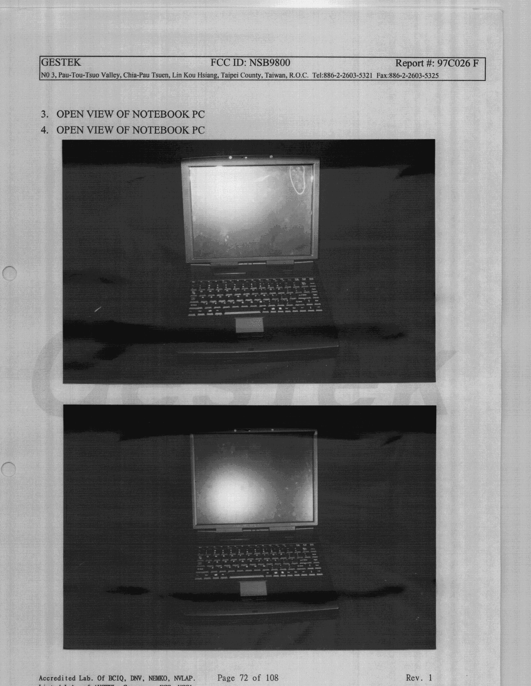
NSB9800
Jul 29, 1998JBC - Part 15 Class B Computing Device/Personal Computer
Equipment Class
JBC - Part 15 Class B Computing Device/Personal Computer