NSJCTT-900AC900 MHz Cordless Telephone
Casil Technology Taiwan Ltd
Click to zoom
Application Details
- Equipment Class
- ETS - Part 15 Cordless Telephone System
- Date of Grant
- Feb 01, 1999
- Application Purpose
- Original Equipment
- Date of Application
- Nov 08, 1998
- Equipment Note
- 900 MHz Cordless Telephone
- Frequency Range
- 926.02500000 - 927.97500000
- Company
- Casil Technology Taiwan Ltd
- Country
- Taiwan
Documents & Files
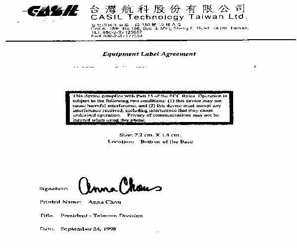
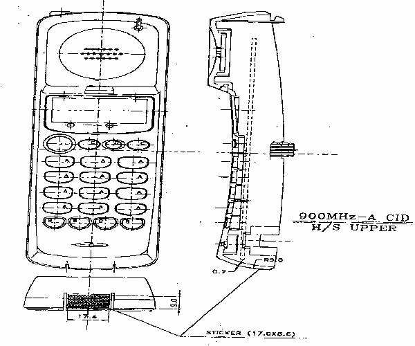
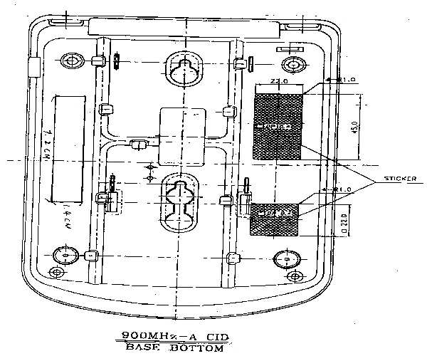
Document Text
Text extracted from the exhibit documents filed with the FCC. Open a document above to read the original.
Users Manual
ANALOG CALLER ID 39708 USER MANUAL FCC INFORMATION FCC Regulations This equipment has been tested and complies with the limits for a Class B digital device, pursuant to part 15 of the FCC rules. These limits are intended to provide reasonable protection against such interference in a residential installation. This equipment generates, uses, and can radiate radio frequency energy and if not installed and used in accordance with the instructions, may cause harmful interference to radio communications. However, there is no guarantee that interference will not occur in a particular installation. If this equipment does cause harmful interference to radio or television reception, which can be determined by turning the equipment off and on, the user is encouraged to try to correct the interference by one or more of the following measures : . Reorient or relocate the receiving antenna. . Increase the separation between the equipment and receiver. . Connect the equipment into an outlet on an electrical circuit different from that to which the receiver is connected. . Consult the dealer or an experienced radio/TV technician. Upon request from your telephone company, you must provide the FCC registration number and the Ringer Equivalence Number(REN) found on the bottom of your 39708 . An FCC compliant telephone cord and modular plug are provided with this equipment. This equipment is designed to be connected to the telephone network or premises wiring using a compatible modular jack which is Part 68 compliant. Telephone Company Procedures The goal of the telephone company is to provide you with the best service it can. In order to do this, it may occasionally have to make changes in its equipment, operations, or procedures. If these changes might affect your service or the operation of your equipment, the telephone company will give you notice in writing to allow you to make any changes necessary to maintain uninterrupted service. If you have any questions about your telephone line, such as how many pieces of equipment you can connect to it, the telephone company will provide this information upon request. In certain circumstances, it may be necessary for the telephone company to request information from you about the equipment which you have connected to your telephone line. Upon request of the telephone company, you must provide the FCC registration number and the Ringer Equivalence Number(REN) of the equipment which is connected to your line. Both of these numbers are listed on the equipment label on the bottom of your 39708 . In most(but not all) areas, the sum of the RENs of all devices connected to one line should not exceed 5. To be certain of the number of devices you may connect to your line as determined by the REN, you should contact your local telephone company. Note: This equipment is hearing aid-compatible(HAC). Type of Service Your cordless telephone is designed for use on standard device telephone lines. The phone connects to the telephone line with a standard jack called the USOC-RJ11C. Connection to telephone company-provided coin service (central office implemented systems) is prohibited. Connection to party line service is subject to State tariffs. If Problems Arise If any of your telephone equipment is not operating properly, you should immediately remove it from your telephone line, as it may cause harm to the telephone network. If the telephone company notes a problem, they may temporarily stop service. When practical, they will notify you before this disconnection. If advance notice is not feasible, you will be notified as soon as possible. When you are notified, you will be given the opportunity to correct the problem and will be informed of your right to file a complaint with the FCC. In the event repairs are ever needed on your cordless telephone, they should be done by an authorized representative of For information, contact Industry Canada(IC)regulations This Class B digital apparatus meets all requirements of the Canadian Interference-Causing Equipment Regulations. Cet appareil numerique de la classe B respecte toutes les exigences du Reglement sur le material brouilleur du Canada. Notice: The Canadian Department of Communications label identifies certified equipment. This certification means the equipment meets certain telecommunications network Protective, operational and safety requirements. The Department does not guarantee the equipment will operate to the customer’s satisfaction. Before installing this equipment users should ensure that it is permissible to be connected to the facilities of the local telecommunications company. The equipment must also be installed using an acceptable method of connection. Sometimes, the company’s inside wiring associated with a single line individual service may be extended with a certified connector assembly (telephone extension cord). The customer should be aware that compliance with these conditions may not prevent degradation of service in some situations. Repairs to certified equipment should be made by an authorized Canadian maintenance Facility by the supplier. Any equipment malfunctions or repairs or alterations made by The user to the equipment may give the telecommunications company cause to request the user to disconnect the equipment. Users should ensure, for their own protection, that the electrical ground connections of the power utility, telephone lines and internal metallic water pipe system, if present, are connected. The precaution may be particularly important in rural areas. Caution: Users should not attempt to make such connections themselves, but should contact the appropriate electric inspection authority or electrician. The Load Number assigned to each terminal device denotes the percentage of the total load to be connected a telephone loop, which is used by the device to prevent overloading. The termination on a loop may consist of any combination of devices subject to the requirement that the total of th…
Text truncated - open the document above for the full version.
Block Diagram
Model: CTT900AC 5. BLOCK DIAGRAM 5-1. BASE MAIN Model: CTT900AC 5-2 BASE RF Model: CTT900AC 5-3 PORTABLE MAIN Model: CTT900AC 5-4 PORTABLE RF Model: CTT900AC
Block Diagram
Model: CTT900AC 5. BLOCK DIAGRAM 5-1. BASE MAIN Model: CTT900AC 5-2 BASE RF Model: CTT900AC 5-3 PORTABLE MAIN Model: CTT900AC 5-4 PORTABLE RF Model: CTT900AC
Cover Letter(s)
January 28, 1999 Federal Communications Commission Application Processing Branch 7435 Oakland Mills Road Columbia, MD 21046 Attention:Mr. Joe Dichoso Reference:FCC ID: NSJCTT-900AC, Confirmation # EA92250, Ref# 5698 Applicant: Casil Technology Dear Mr. Dichoso: Enclosed please find the letter and information from our client regarding the security code requirements in Section 15.214(d) for their product. The application check (filing fee) which was paid by Intertek Testing Services was sent to Mellon Bank the third week of November 1998 with information as follows: Check No.:241254 Amount:$940.00 Payable to:Federal Communications Comm. Date of the check:10/20/98 Should there be any questions, please contact David Chernomordik or the undersigned. Regards, Gaspara Lim gcl/ Enclosures cc:Bette Taube
External Photos
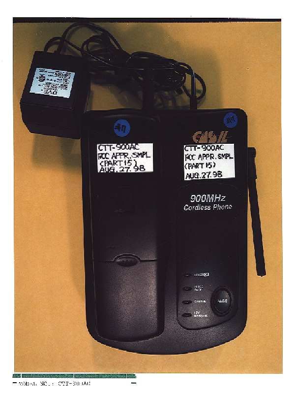
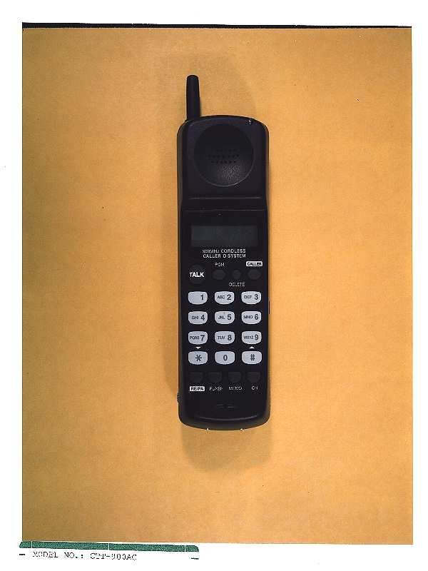
SOOMHz Cordless Phme u -MODEL NO.: CTT-900AC
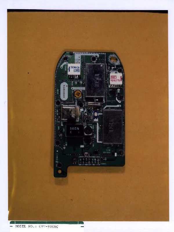
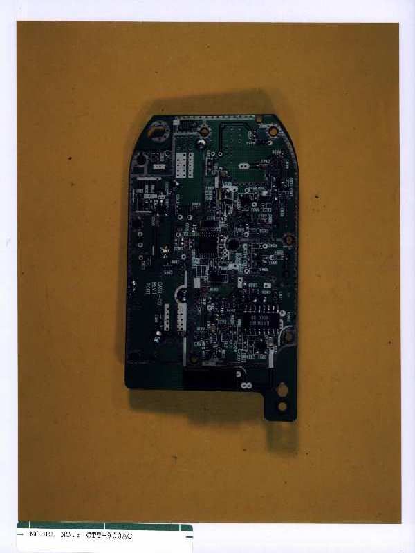
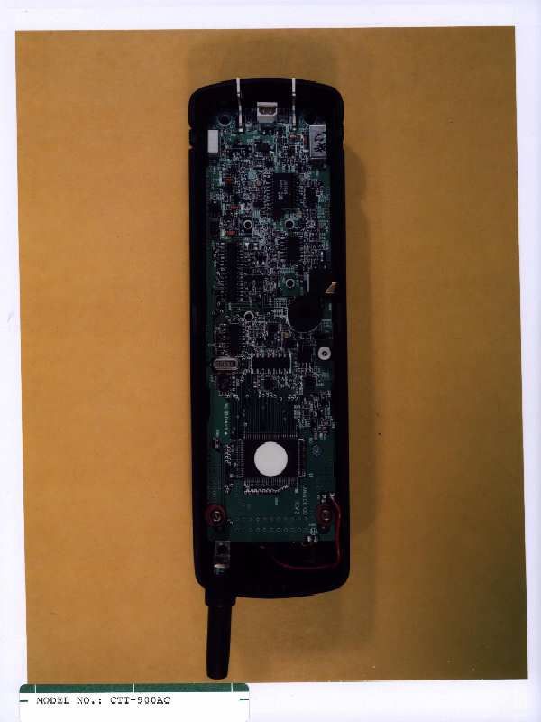
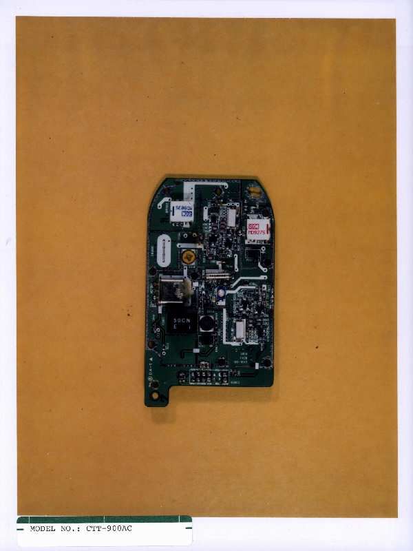
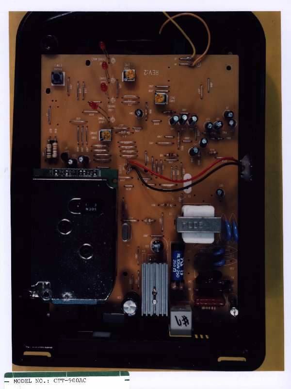
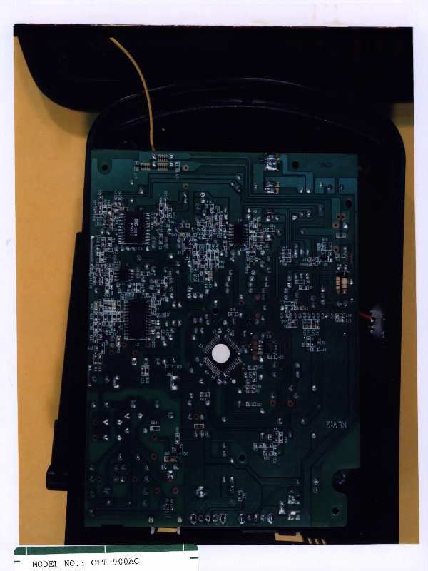
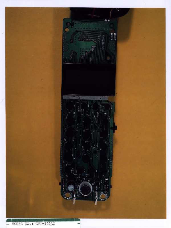
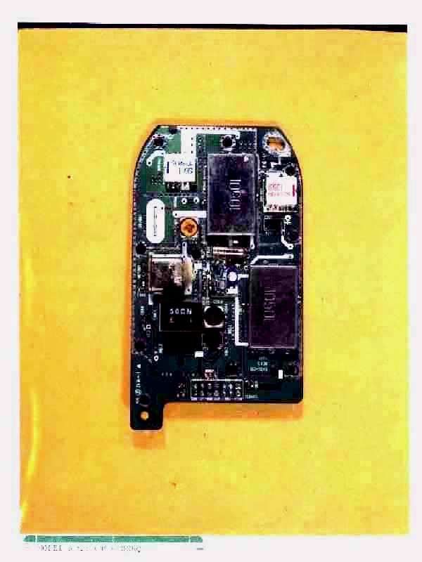
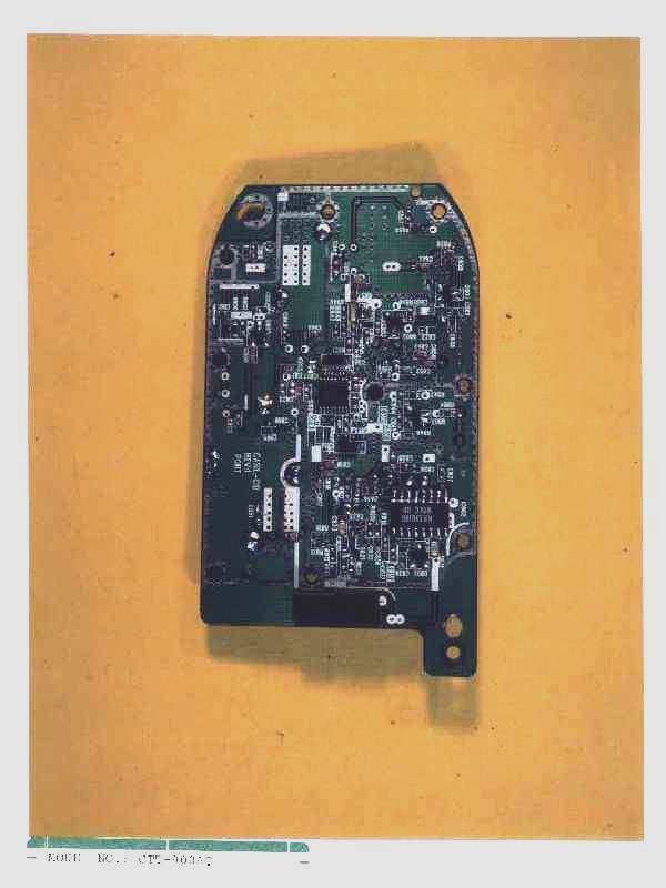
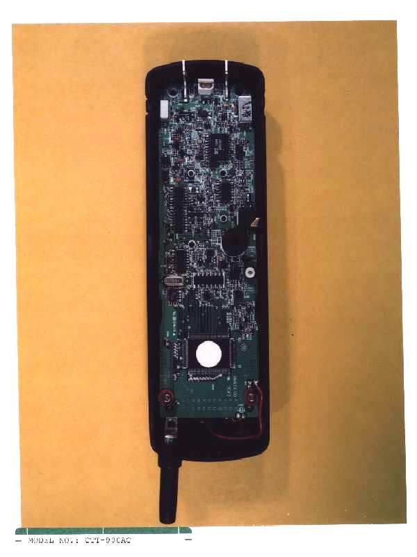
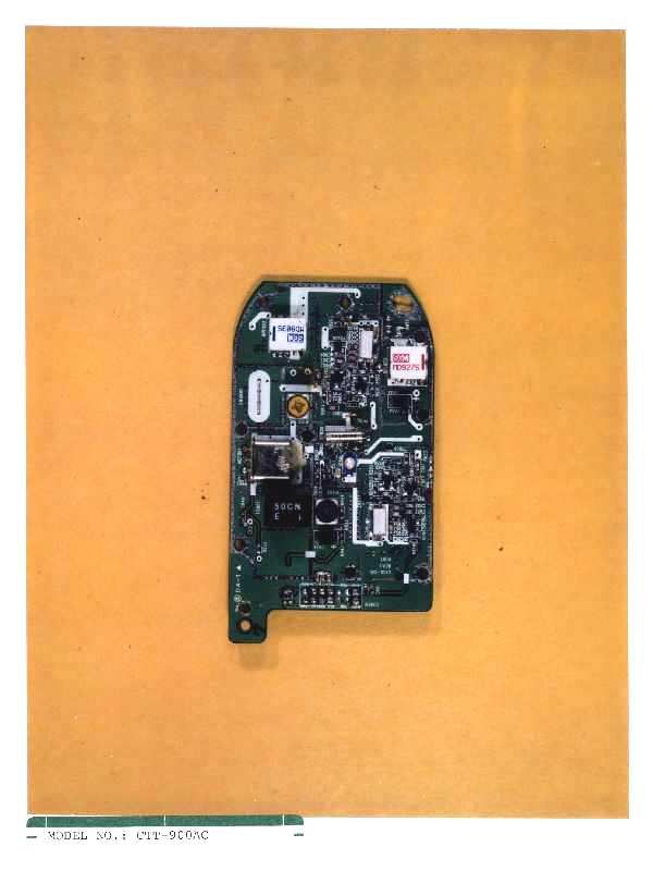
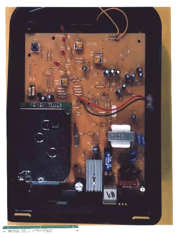
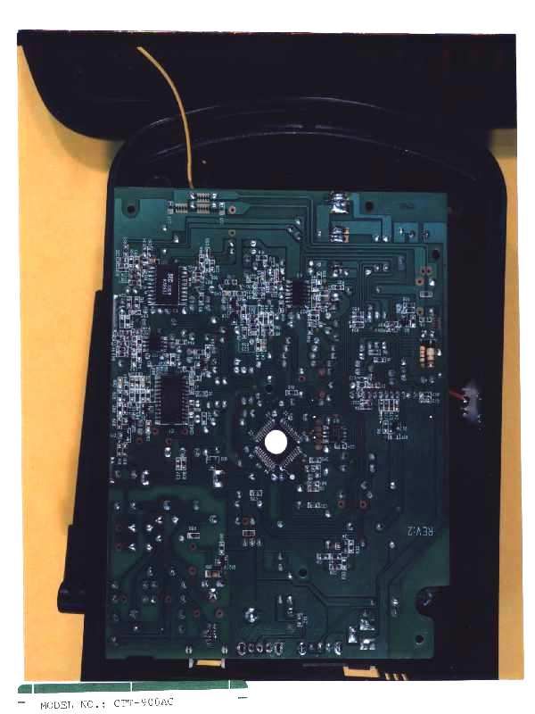
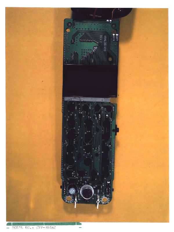
Internal Photos
i I - MODEL NO.: CTT-900AC
Schematics
Model: CTT900AC 6. CIRCUIT DIAGRAM 6-1 BASE MAIN Model: CTT900AC 6-2 BASE RF Model: CTT900AC 6-3 BASE VCO Model: CTT900AC 6-4 PORTABLE MAIN Model: CTT900AC 6-5 PORTABLE RF Model: CTT900AC 6-6 PORTABLE VCO
Schematics
Model: CTT900AC 6. CIRCUIT DIAGRAM 6-1 BASE MAIN Model: CTT900AC 6-2 BASE RF Model: CTT900AC 6-3 BASE VCO Model: CTT900AC 6-4 PORTABLE MAIN Model: CTT900AC 6-5 PORTABLE RF Model: CTT900AC 6-6 PORTABLE VCO
Test Report
i Intertek Testing Services APPLICATION FOR FCC CERTIFICATION Casil Technology Taiwan Ltd. 900 MHz Cordless Telephone Model: CTT-900AC FCC ID: NSJCTT-900AC Report # J98025571 Number of Pages: Date of Report: September 23, 1998 This report shall not be reproduced except in full, without written approval of Intertek Testing Services. This report must not be used to claim product endorsement by NVLAP or any agency of the U.S. Government. The results contained in this report were derived from measurements performed on the identified test samples. Any implied performance of other samples on this report is dependent on the representative of the samples tested. FCC Part 15.249 Tx Cert, Ver 5/97k:\..\fcc\15249.cer Intertek Testing Services 1365 Adams Court, Menlo Park, CA 94025 Casil Technology Taiwan Ltd., 900 MHz Cordless TelephoneDate of Test: Sept. 8, 9, & 10, 1998 FCC ID: NSJCTT-900AC Report # J98025571FCC Part 15.249 Certification ii Table of Contents 0.0Summary of Test Results ...............................................1 1.0General Description...................................................2 1.1Product Description..............................................2 1.2Related Submittal(s) Grants........................................3 1.3Test Methodology...............................................3 1.4Test Facility....................................................3 2.0System Test Configuration .............................................4 2.1Justification....................................................4 2.2EUT Exercising Software..........................................4 2.3System Test Configuration.........................................5 2.3.1Support Equipment.........................................5 2.3.2Block Diagram of Test Setup.................................5 2.4Equipment Modification...........................................6 2.5Additions, deviations and exclusions from standards......................6 3.0Emission Results .....................................................7 3.1Field Strength Calculation..........................................8 3.3Radiated Emission Data...........................................9 3.5Conducted Emission Data.........................................10 4.0Out of Band Emission Plot ............................................11 5.0Antenna Requirement................................................12 6.0List of Exhibits.....................................................13 Intertek Testing Services 1365 Adams Court, Menlo Park, CA 94025 Casil Technology Taiwan Ltd., 900 MHz Cordless TelephoneDate of Test: Sept. 8, 9, & 10, 1998 FCC ID: NSJCTT-900AC Report # J98025571FCC Part 15.249 Certification 1 0.0Summary of Test Results Casil Technology Taiwan Ltd. - Model No.: CTT-900AC FCC ID: NSJCTT-900AC TESTREFERENCERESULTS Radiated Emission15.249Complies Conducted Emission15.207Complies Antenna Requirement15.203Complies Test Engineer: Date: November 6, 1998 Ahmad Safdari EMC Site Mgr.: Date: November 6, 1998 David Chernomordik Intertek Testing Services 1365 Adams Court, Menlo Park, CA 94025 Casil Technology Taiwan Ltd., 900 MHz Cordless TelephoneDate of Test: Sept. 8, 9, & 10, 1998 FCC ID: NSJCTT-900AC Report # J98025571FCC Part 15.249 Certification 2 1.0General Description 1.1Product Description The Casil Technology Model CTT-900AC is a 900 MHz cordless telephone. Frequency (MHz) BaseHandset 902.025 - 903.975926.025 - 927.975 Intertek Testing Services 1365 Adams Court, Menlo Park, CA 94025 Casil Technology Taiwan Ltd., 900 MHz Cordless TelephoneDate of Test: Sept. 8, 9, & 10, 1998 FCC ID: NSJCTT-900AC Report # J98025571FCC Part 15.249 Certification 3 1.2Related Submittal(s) Grants This is an Application for Certification of a cordless telephone system. The Part 68 application has already been submitted. 1.3Test Methodology Both AC mains line-conducted and radiated emission measurements were performed according to the procedures in ANSI C63.4 (1992). All measurements were performed in Open Area Test Sites. Preliminary scans were performed in the Open Area Test Sites only to determine worst case modes. For each scan, the procedure for maximizing emissions in Appendices D and E were followed. All Radiated tests were performed at an antenna to EUT distance of 3 meters, unless stated otherwise in the "Justification Section" of this Application. 1.4Test Facility The open area test site and conducted measurement facility used to collect the radiated data is Site 1. This test facility and site measurement data have been fully placed on file with the FCC and NVLAP accredited. Intertek Testing Services 1365 Adams Court, Menlo Park, CA 94025 Casil Technology Taiwan Ltd., 900 MHz Cordless TelephoneDate of Test: Sept. 8, 9, & 10, 1998 FCC ID: NSJCTT-900AC Report # J98025571FCC Part 15.249 Certification 4 2.0System Test Configuration 2.1Justification For emission testing, the equipment under test (EUT) was configured for testing in a typical fashion (as a customer would normally use it). During testing, all cables were manipulated to produce worst case emissions. For the measurements, the EUT is attached to a cardboard box (if necessary) and placed on the wooden turntable. If the EUT attaches to peripherals, they are connected and operational (as typical as possible). The EUT is wired to transmit full power without modulation. The signal is maximized through rotation and placement in the three orthogonal axes. The antenna height and polarization are varied during the search for maximum signal level. The antenna height is varied from 1 to 4 meters. Detector function is in peak mode. Radiated emissions are taken at three meters unless the signal level is too low for measurement at that distance. If necessary, a pre- amplifier is used and/or the test is conducted at a closer distance. All readings are extrapolated back to the equivalent three meter reading using inverse scaling with distance. 2.2EUT Exercising Software The EUT exercise program used duri…
Text truncated - open the document above for the full version.
Test Setup Photos
i Test Set-up Photos (Radiated & Line Conducted Emissions) RADIATED LINE CONDUCTED
Contact Information
Technical Contact
INTERTEK TESTING SERVICESDAVID CHERNOMORDIK
650-463-2900
1365 ADAMS COURT · MENLO PARK, California · United States
Non-Technical Contact
CASIL TECHNOLOGY TAIWAN LTD.ANNA CHOU
886-2-27125657
Test Firm
Intertek Testing Services NA Inc.John Quigley
Technical Specifications
| # | Rule Parts | Frequency Range | Power Output |
|---|---|---|---|
| 2 | 15C | 926.025 MHz - 927.975 MHz | - |
Other Applications from Casil Technology Taiwan Ltd

NSJCTT-900AB
Aug 10, 1998Cordless Telephone
Equipment Class
DXT - Part 15 Low Power Transceiver, Rx Verified