NSQLAP-4200-AWhereNet Location Sensor
Zebra Technologies Corporation
Click to zoom
Application Details
- Equipment Class
- DSS - Part 15 Spread Spectrum Transmitter
- Date of Grant
- Apr 01, 2002
- Application Purpose
- Original Equipment
- Date of Application
- Apr 01, 2002
- Equipment Note
- WhereNet Location Sensor
- Frequency Range
- 2412.00000000 - 2462.00000000
- Country
- United States
Documents & Files
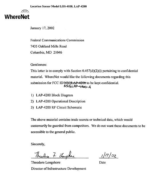
Document Text
Text extracted from the exhibit documents filed with the FCC. Open a document above to read the original.
Users Manual
___________________________________________________________________________ Infrastructure Installation Guide ___________________________________________________________________________ 1 Location Sensor Installation Guide D0405 rev PA6 Copyright WhereNet, Corp. 2001 WhereNet Confidential Location Sensor (including Locating Access Point) Installation Guide ___________________________________________________________________________ Infrastructure Installation Guide ___________________________________________________________________________ 2 Location Sensor Installation Guide D0405 rev PA6 Copyright WhereNet, Corp. 2001 WhereNet Confidential Typographical Conventions Warnings call attention to a procedure or practice that could result in personal injury if not correctly performed. Do not proceed until you fully understand and meet the required conditions. Cautions call attention to an operation procedure or practice that could damage the product, or degrade performance if not correctly performed. Do not proceed until understanding and meeting these required conditions. Notes provide information that can be helpful in understanding the operation of the product. _____________ _____________ ____________ ______________ ____________ Note ____________ ___________________________________________________________________________ Infrastructure Installation Guide ___________________________________________________________________________ 3 Location Sensor Installation Guide D0405 rev PA6 Copyright WhereNet, Corp. 2001 WhereNet Confidential Document Revision History Revision Description of Changes Date Approved PA6 Preliminary 1/20/02 ___________________________________________________________________________ Infrastructure Installation Guide ___________________________________________________________________________ 4 Location Sensor Installation Guide D0405 rev PA6 Copyright WhereNet, Corp. 2001 WhereNet Confidential Table of Contents Page 1 DOCUMENT OVERVIEW 6 2 PRODUCT DESCRIPTION AND FEATURES 6 3 PRODUCT SPECIFICATIONS 8 4 PARTS AND TOOLS 9 5 CONFIGURATION 13 6 ASSEMBLY INSTRUCTIONS 17 7 FCC INFORMATION 17 8 MOUNTING OVERVIEW 19 9 CABLING 23 10 LOCATION SENSOR INSTALLATION CHECKLIST 27 Table of Figures Page FIGURE 1 ALL WEATHER OMNI ANTENNA 11 FIGURE 2 INDOOR OFFICE OMNI ANTENNA 11 FIGURE 3 FLAT PANEL DIRECTIONAL ANTENNA 11 FIGURE 4 OPTIONAL HIGH GAIN ANTENNA 11 FIGURE 5 POWER SUPPLY 12 FIGURE 6 OUTDOOR P.S. HOUSING 12 FIGURE 7 RJ CABLE TOOL 13 FIGURE 8 FLUKE LAN CABLEMETER 13 FIGURE 9 LAP-4200 LABEL 15 ___________________________________________________________________________ Infrastructure Installation Guide ___________________________________________________________________________ 5 Location Sensor Installation Guide D0405 rev PA6 Copyright WhereNet, Corp. 2001 WhereNet Confidential FIGURE 10 WALL MOUNTING HOLE DIMENSIONS 21 FIGURE 11 LOCATION SENSOR CONNECTIONS 23 FIGURE 12 LOCATION SENSOR LED INDICATORSLED INDICATORS 33 ___________________________________________________________________________ Infrastructure Installation Guide ___________________________________________________________________________ 6 Location Sensor Installation Guide D0405 rev PA6 Copyright WhereNet, Corp. 2001 WhereNet Confidential 1 DOCUMENT OVERVIEW This document describes the physical installation and basic configuration of the Location Sensor product. The site design is detailed in the D0406 Location Sensor Placement Guide. 2 PRODUCT DESCRIPTION AND FEATURES The Location Sensor receives the signals transmitted by the WhereTags, which are attached to the tracked assets. The decoded tag information is time stamped and routed to a PC for additional processing. The locate algorithm running on the PC calculates the tag position based on the time stamps of multiple Location Sensors, and reports that position to the database where it is displayed by Resource Manager. There are two separate Location Sensor models: • LOS-4100 (802.3 Wired Ethernet) • LAP-4200 (with 802.11b Wireless LAN Access Point, also known as a Locating Access Point) The difference between the two models is that the LAP-4200 contains an Access Point, while the LOS-4100 does not. These units are identical in appearance; the ___________________________________________________________________________ Infrastructure Installation Guide ___________________________________________________________________________ 7 Location Sensor Installation Guide D0405 rev PA6 Copyright WhereNet, Corp. 2001 WhereNet Confidential only way to distinguish them is by the model number on the housing. Note that both units have a wired Ethernet port; the LAP-4200 has a can function as either a client bridge or an access point. Both units also include a low power transmitter which is used to distribute configuration data, and timing signals to other Location Sensor units. This transmitter has the same transmitter characteristics as a tag. Features include: • Outdoor weatherproof housing • Wireless data transport capability • Wireless Timing capability There are three separate antenna options for the Location Sensor. In addition, there is an optional high gain Wireless LAN Access Point directional antenna for installations in which the standard antennas do not proved the range required to communicate with the base access point. The available antennas are listed in section 4 below. ___________________________________________________________________________ Infrastructure Installation Guide ___________________________________________________________________________ 8 Location Sensor Installation Guide D0405 rev PA6 Copyright WhereNet, Corp. 2001 WhereNet Confidential 3 PRODUCT SPECIFICATIONS 3.1 Mechanical Size: 10.3 x 3.2 x 12.0 261 x 80 x 305 in (HxDxW) mm Weight: 8.0 3.6 Lbs kg 3.2 Electrical Voltage: 18 to 36 36 nominal Vdc Current: 1.5 (max) Amps Pwr Diss: 25 (max) Watts AC Power 1 100- 240 Vac 1 With recommended power supply 3.3 Environmental Operating Tempera…
Text truncated - open the document above for the full version.
Attestation Statements
Location Sensor Model LOS-4100, LAP-4200 107 W. McKinney Ave Rogersville, TN 37857 (423) 272-9279 -1- Processing Gain The processing gain for the WhereNet system is measured using the CW jamming margin method as described in CFR 47 Part 15.247(e)(2) where Gp = S/N0 + Mj + Lsys. For this system, the BER requirements are derived from the required message error rate because the direct sequence spread spectrum (DSSS) receiver can provide metrics for message errors, but not actual bit errors. (The system uses burst transmissions, and the bursts are discarded if a single bit error occurs.) The processing gain of the WhereNet system is: Gp = 10 x Log(Chip rate/ Data rate) = 10 x Log(30.52M/59.73K) = 10 x Log(511) = 27 dB The remainder of this memo includes the derivation of the S/N 0 of the WhereNet System, a description of the test setup and procedure, a summary of the results of the testing, and an attachment which contains the detailed data from the test. WhereNet’s RTLS system uses a 48-bit message length. The nature of the WhereNet System is such that was not practical to directly measure processing gain by observing signal to noise ratio at the output of the receiver’s demodulator with and without the presence DSSS spreading code. The Location Sensor’s logic does not permit it to be placed in a continuous DSSS test mode as is available in the Handheld Communicator. Therefore we chose to make the CW jammer measurement using the WhereNet HPC- Location Sensor Model LOS-4100, LAP-4200 107 W. McKinney Ave Rogersville, TN 37857 (423) 272-9279 -2- 2000-00AA Handheld Communicator. This was because the Handheld Communicator could be placed in a mode where it repeated it DSSS message in a loop at a rapid rate. The transmit circuitry in the LAP-4200 and LOS-4100 blinks randomly at a much slower rate. This made it impractical to measure the required 1220 data points in a reasonable timeframe. The WhereNet Location Sensors models LAP-4200 and LOS- 4100 and the HPC-2000-00AA Handheld Communicator have identical RFIC based transmitters, employ the same parts and transmit identical DSSS protocols. They are both used with and demodulated by the same receiver. Because the Location Sensor and Handheld are essentially identical DSSS emitters, we are submitting data for the Handheld only and request that it be applied to the Location Sensor. The data below was measured with the Model HPC-2000-00AA Handheld Communicator. The receiver used for this test is a WhereNet model FEC-3500-00AA, which contains the same receiver demodulator as the Location Sensors. The result of the test is a measured processing gain of 15.9 dB. This result satisfies the CFR 47 Part 15.247 requirement of a minimum of 10 dB of processing gain. BER Requirements Derivation A message throughput rate of 75 percent is acceptable for reliable operations. The burst transmission consists of 48 bits and a single bit error will cause a message error. The message error rate is related to the BER by a simple probability equation. The probability of having zero bits in error out of a 48-bit transmission is given by, Pm = (1 – Pb) L Location Sensor Model LOS-4100, LAP-4200 107 W. McKinney Ave Rogersville, TN 37857 (423) 272-9279 -3- Where, Pm is the probability of receiving a message without errors Pb is the bit error rate probability or BER L is the length of the message Solving for Pb, given Pm = 75 %, we have, Pb = 1 – (Pm) (1/L) or, Pb = 1 – (.75) (1/44) = 0.00598 Test Setup and Procedure The processing gain test set-up consists of the following equipment connected as shown below. • WhereNet Model HPC-2000-00AA Handheld Communicator (Unit Under Test) • Notebook Model 6100T Laptop Computer to control UUT • HP-8648C Signal Generator • HP 436A Power mMeter and HP 8484A Power Sensor • HP-797D Directional Coupler • HP 8494A and HP8496A Step Attenuators • WhereNet Model FEC-3500-00AA DSSS Receiver Location Sensor Model LOS-4100, LAP-4200 107 W. McKinney Ave Rogersville, TN 37857 (423) 272-9279 -4- Test Setup Diagram HP-8648C Signal Generator HP-8494A& HP-8496A StepAttenuators (0-81dB) Notebook6100T LaptopComputer HPC-2000-00AA WiDataPCMCIA Card FEC-3500-00AA WhereNetDSSS Receiver HP-436A Power Meter HP-8484A Power Head ConnecttopointA forcalibration HP-797D -20dB Directional Coupler A Test Procedure The test was conducted by first putting the Handheld Communicator in a continuous DSSS test mode and measuring the power level on the power meter. The jammer level was then set to 0 dB relative to the carrier level and measured using the power meter and the signal generator’s internal attenuator. A step attenuator was used to adjust the jammer level relative to the signal. The Handheld Communicator left in the continuous DSSS test mode. Message error rate software was written to record the number of good messages received in a group of 128 messages. The passband of the system is +/- 30.5 MHz, so there are 61 MHz/50 KHz = 1220 test points across the passband of the system. The jammer frequency was set to the lowest frequency in the passband, and the Location Sensor Model LOS-4100, LAP-4200 107 W. McKinney Ave Rogersville, TN 37857 (423) 272-9279 -5- jammer level was adjusted until the good message rate measured 96/128 for the nominal 75 % throughput. The jammer was then stepped across the passband in 50 KHz increments and the highest jammer level which still allowed 75% throughput was logged at each frequency. This information was recorded in an Excel spreadsheet. Test Results Using the jamming margin method, the processing gain (in dB) is defined as Gp = S/N + Mj + Lsys. The required S/N, was derived from the equation Pb = ½ exp( - S/N ) for non coherent DBPSK waveforms. Using the BER of 0.00598 determined above resulted in a S/N of 6.5 dB. To determine Mj, the test data from the jamming margin test was utilized. An Excel Spreadsheet showing the maximum J/S ratio which allowed a good message rate of 75 % for each of the 1220 frequencies in the passband has b…
Text truncated - open the document above for the full version.
Attestation Statements
Location Sensor Model LOS-4100, LAP-4200 17 W. McKinney Ave Rogersville, TN 37857 (423) 272-9279 LAP-4200 w/ Locating Access Point There are two separate Location Sensor models: • LOS-4100 (802.3 Wired Ethernet) • LAP-4200 (with 802.11b Wireless LAN Access Point, also known as a Locating Access Point) The LAP-4200 contains a Symbol Technologies Spectrum 24 HR WLAN PC Card Model LA-4131 Access Point (FCC ID H9PLA4131M). No changes have been made to the LA-4131 PC Card Access Point; it is utilized “as is” purchased from Symbol Technologies. The included Access Point receives and transmits 2.4 GH DSSS signals from 802.11 compliant handheld communicator units. 4/2/02 _________________________________ ___________ Theodore Longshore Date Director of Infrastructure Development
External Photos
ETS02-001APage 1 of 7 SUBMITTAL PHOTOGRAPH End Showing Ports ETS02-001APage 2 of 7 SUBMITTAL PHOTOGRAPH Front ETS02-001APage 3 of 7 SUBMITTAL PHOTOGRAPH Back ETS02-001APage 4 of 7 SUBMITTAL PHOTOGRAPH Top Patch Antenna ETS02-001APage 5 of 7 SUBMITTAL PHOTOGRAPH Bottom Patch Antenna ETS02-001APage 6 of 7 SUBMITTAL PHOTOGRAPH Top PCB in Patch Antenna ETS02-001APage 7 of 7 SUBMITTAL PHOTOGRAPH Bottom Antenna
ID Label/Location Info
-A
ID Label/Location Info
Location Sensor Model OS-4100, LAP-4200 107 W. McKinney Ave Rogersville, TN 37857 (423) 272-9279 Label/Location Information Label Material: adhesive backed polyester Label position on underside of unit: 5.25 in 0.75 in -A -A
Internal Photos
ETS02-001APage 1 of 49 SUBMITTAL PHOTOGRAPH Top Removed - Overview ETS02-001APage 2 of 49 SUBMITTAL PHOTOGRAPH Overview ETS02-001APage 3 of 49 SUBMITTAL PHOTOGRAPH Inside Back ETS02-001APage 4 of 49 SUBMITTAL PHOTOGRAPH Top Rear PCB Left Third ETS02-001APage 5 of 49 SUBMITTAL PHOTOGRAPH Bottom Rear PCB Left Third ETS02-001APage 6 of 49 SUBMITTAL PHOTOGRAPH Top Rear PCB Right Third ETS02-001APage 7 of 49 SUBMITTAL PHOTOGRAPH Overview Board Back ETS02-001APage 8 of 49 SUBMITTAL PHOTOGRAPH Overview Board Top ETS02-001APage 9 of 49 SUBMITTAL PHOTOGRAPH PCB #2 – Back 1 ETS02-001APage 10 of 49 SUBMITTAL PHOTOGRAPH PCB #2 – Back 2 ETS02-001APage 11 of 49 SUBMITTAL PHOTOGRAPH PCB #2 – Back 3 ETS02-001APage 12 of 49 SUBMITTAL PHOTOGRAPH PCB #2 – Back 4 ETS02-001APage 13 of 49 SUBMITTAL PHOTOGRAPH PCB #2 – Back 5 ETS02-001APage 14 of 49 SUBMITTAL PHOTOGRAPH PCB #2 – Back 6 ETS02-001APage 15 of 49 SUBMITTAL PHOTOGRAPH PCB #2 - Back Center 1 ETS02-001APage 16 of 49 SUBMITTAL PHOTOGRAPH PCB #2 – Back Center 2 ETS02-001APage 17 of 49 SUBMITTAL PHOTOGRAPH PCB #2 – Back Center 3 ETS02-001APage 18 of 49 SUBMITTAL PHOTOGRAPH PCB #2 – Back Center 4 ETS02-001APage 19 of 49 SUBMITTAL PHOTOGRAPH PCB #2 – Back Center 5 ETS02-001APage 20 of 49 SUBMITTAL PHOTOGRAPH PCB #2 – Back Center 6 ETS02-001APage 21 of 49 SUBMITTAL PHOTOGRAPH PCB #2 – Back Top 1 ETS02-001APage 22 of 49 SUBMITTAL PHOTOGRAPH PCB #2 – Back Top 2 ETS02-001APage 23 of 49 SUBMITTAL PHOTOGRAPH PCB #2 – Back Top 3 ETS02-001APage 24 of 49 SUBMITTAL PHOTOGRAPH PCB #2 – Back Top 4 ETS02-001APage 25 of 49 SUBMITTAL PHOTOGRAPH PCB #2 – Back Top 5 ETS02-001APage 26 of 49 SUBMITTAL PHOTOGRAPH PCB #2 – Back Top 6 ETS02-001APage 27 of 49 SUBMITTAL PHOTOGRAPH Bottom Front PCB #2 – Top 1 ETS02-001APage 28 of 49 SUBMITTAL PHOTOGRAPH Bottom Front PCB #2 – Top 2 ETS02-001APage 29 of 49 SUBMITTAL PHOTOGRAPH Bottom Front PCB #2 – Top 3 ETS02-001APage 30 of 49 SUBMITTAL PHOTOGRAPH Bottom Front PCB #2 – Top 4 ETS02-001APage 31 of 49 SUBMITTAL PHOTOGRAPH Bottom Front PCB #2 – Top 5 ETS02-001APage 32 of 49 SUBMITTAL PHOTOGRAPH Bottom Front PCB #2 – Top 6 ETS02-001APage 33 of 49 SUBMITTAL PHOTOGRAPH Bottom Front PCB #2 – Top 7 ETS02-001APage 34 of 49 SUBMITTAL PHOTOGRAPH Bottom Front PBC #2 – Center 1 ETS02-001APage 35 of 49 SUBMITTAL PHOTOGRAPH Bottom Front PCB #2 – Center 2 ETS02-001APage 36 of 49 SUBMITTAL PHOTOGRAPH Bottom Front PCB #2 – Center 3 ETS02-001APage 37 of 49 SUBMITTAL PHOTOGRAPH Bottom Front PCB #2 – Center 4 ETS02-001APage 38 of 49 SUBMITTAL PHOTOGRAPH Bottom Front PCB #2 – Center 5 ETS02-001APage 39 of 49 SUBMITTAL PHOTOGRAPH Bottom Front PCB #2 – Center 6 ETS02-001APage 40 of 49 SUBMITTAL PHOTOGRAPH Bottom Front PCB #2 – Center 7 ETS02-001APage 41 of 49 SUBMITTAL PHOTOGRAPH Bottom Row Top PCB #2 – 1 ETS02-001APage 42 of 49 SUBMITTAL PHOTOGRAPH Bottom Row Top PCB #2 – 2 ETS02-001APage 43 of 49 SUBMITTAL PHOTOGRAPH Bottom Row Top PCB #2 – 3 ETS02-001APage 44 of 49 SUBMITTAL PHOTOGRAPH Bottom Row Top PCB #2 – 4 ETS02-001APage 45 of 49 SUBMITTAL PHOTOGRAPH Bottom Row Top PCB #2 – 5 ETS02-001APage 46 of 49 SUBMITTAL PHOTOGRAPH Bottom Row Top PCB #2 – 6 ETS02-001APage 47 of 49 SUBMITTAL PHOTOGRAPH Bottom Row Top PCB #2 – 7 ETS02-001APage 48 of 49 SUBMITTAL PHOTOGRAPH PCMCIA Card Bottom ETS02-001APage 49 of 49 SUBMITTAL PHOTOGRAPH PCMCIA Card Top
RF Exposure Info
MPE Calculations Formula S=PG/4πR 2 Where S is power density in mW/cm P is the transmit power in mW at the antenna G is the gain of the antenna in dimensionless units R is the distance in cm to the antenna. For mobile devices in GENERAL POPULATION / UNCONTROLLED EXPOSURE the power density limit is 1 mW/cm 2 Therefore the MPE limit is MPE=sqrt(PG/4 π S) MPE calculation. P= 60 mW * 0.72 source based averaging. = 43.2 mW G= 1.8 dBi = 1.51 dimensionless S= 1 mW/cm 2 EIRP = 65 mW MPE=sqrt(43.2 *1.51 / 4π ) = 2.28 cm
Test Report
Page 1 of 65 Report No: FC02-002C TUV RHEINLAND ADDENDUM TO FC02-002B FOR THE WHERENET LOCATION SENSOR, LAP-4200 FCC PART 15 SUBPART C SECTIONS 15.247, 15.207 & 15.209 AND FCC PART 15 SUBPART B SECTION 15.109 CLASS B COMPLIANCE DATE OF ISSUE: MARCH 27, 2002 PREPARED FOR: TUV Rheinland 1279 Quarry Lane, Suite A Pleasanton, CA 94566 PREPARED BY: Mary Ellen Clayton CKC Laboratories, Inc. 5473A Clouds Rest Mariposa, CA 95338 P.O. No.: W.O. No.: P2172507.01 78024 Date of test: November 26 - January 22, 2002 Report No.: FC02-002C This report contains a total of 65 pages and may be reproduced in full only. Partial reproduction may only be done with the written consent of CKC Laboratories, Inc. Page 2 of 65 Report No: FC02-002C TABLE OF CONTENTS Administrative Information ............................................................................................. 4 Summary of Results......................................................................................................... 5 Modifications Required for Compliance ......................................................................... 5 Approvals......................................................................................................................... 5 Equipment Under Test (EUT) Description...................................................................... 6 Equipment Under Test..................................................................................................... 6 Peripheral Devices ........................................................................................................... 7 15.33 Frequency Range Tested ....................................................................................... 8 EUT Operating Frequency............................................................................................... 8 Temperature and Humidity During Testing .................................................................... 8 Report of Measurements.................................................................................................. 9 Table 1: 15.247(b)(1) Peak Power Emission: OATS Testing ............................. 9 Table 2: 15.247(b)(1) Peak Power Emission: Antenna Terminal Testing .......... 10 Table 3: 15.247(c)/15.209 Highest Radiated Emission Levels: 9kHz-30MHz ... 11 Table 4: 15.247(c)/15.209 Highest Radiated Emission Levels: 30-1000MHz.... 12 Table 5: 15.247(c)/15.209 Highest Radiated Emission Levels: 1-26.5GHz ....... 14 Table 6: 15.207 Highest Conducted Emission Levels:........................................ 15 Table 7: 15.109 Highest Radiated Emission Levels: 1-12.8GHz........................ 16 Measurement Uncertainty................................................................................................ 17 EUT Setup .......................................................................................................................17 Correction Factors ........................................................................................................... 18 Table A: Sample Calculations ............................................................................. 18 Test Instrumentation and Analyzer Settings.................................................................... 19 Table B: 15.35 Analyzer Bandwidth Settings Per Frequency Range.................. 19 Spectrum Analyzer Detector Functions............................................................... 20 Peak ......................................................................................................... 20 Quasi-Peak............................................................................................... 20 Average.................................................................................................... 20 EUT Testing ....................................................................................................................21 Radiated Emissions ............................................................................................. 21 Mains Conducted Emissions ............................................................................... 21 Antenna Conducted Emissions ............................................................................ 22 Transmitter Characteristics.............................................................................................. 22 15.203 Antenna Requirements ............................................................................ 22 15.205 Restricted Bands ...................................................................................... 22 15.247(a)(2) Bandwidth – Direct Sequence ........................................................ 22 15.247(b)(1) Peak Output Power......................................................................... 23 15.247(b)(3)(i) Directional Gain Reduction ........................................................ 23 15.247(d) Peak Power Spectral Density .............................................................. 23 15.215 Additional Provisions To The General Radiated Emission Limitations . 23 Page 3 of 65 Report No: FC02-002C Appendix A: Test Setup Photographs ............................................................................. 24 Photograph Showing Radiated Emissions ........................................................... 25 Photograph Showing Radiated Emissions ........................................................... 26 Photograph Showing Radiated Emissions ........................................................... 27 Photograph Showing Radiated Emissions ........................................................... 28 Photograph Showing Radiated Emissions ........................................................... 29 Photograph Showing Mains Conducted Emissions............................................. 30 Photograph Showing Mains Conducted Emissions............................................. 31 Appendix B: Test Equipment List ......................…
Text truncated - open the document above for the full version.
Test Report
Page 1 of 7 Report No: FC02-002D TUV RHEINLAND ADDENDUM TO FC02-002C FOR THE WHERENET LOCATION SENSOR, LAP-4200 FCC PART 15 SUBPART C SECTIONS 15.247, 15.207 & 15.209 AND FCC PART 15 SUBPART B SECTION 15.109 CLASS B COMPLIANCE DATE OF ISSUE: APRIL 2, 2002 PREPARED FOR: TUV Rheinland 1279 Quarry Lane, Suite A Pleasanton, CA 94566 PREPARED BY: Joyce Walker CKC Laboratories, Inc. 5473A Clouds Rest Mariposa, CA 95338 P.O. No.: W.O. No.: P2172507.01 78024 Date of test: November 26 – April 2, 2002 Report No.: FC02-002D This report contains a total of 7 pages and may be reproduced in full only. Partial reproduction may only be done with the written consent of CKC Laboratories, Inc. Page 2 of 7 Report No: FC02-002D TABLE OF CONTENTS Administrative Information ............................................................................................. 3 Summary of Results......................................................................................................... 4 Modifications Required for Compliance ......................................................................... 4 Approvals......................................................................................................................... 4 Equipment Under Test (EUT) Description...................................................................... 5 Equipment Under Test..................................................................................................... 5 Peripheral Devices ........................................................................................................... 6 Table 1: 15.247(b)(1) Peak Power Emission: Antenna Terminal Testing ...................... 7 Page 3 of 7 Report No: FC02-002D CKC Laboratories, Inc. has received Certificates of Accreditation from the following agencies: A2LA (USA); DATech (Germany); BSMI (Taiwan); Nemko (Norway); and GOST (Russia). CKC Laboratories, Inc has received test site Registration Acceptance from the following agencies: FCC (USA); VCCI (Japan); and Industry Canada. CKC Laboratories, Inc. has received Letters of Acceptance through an MRA for the following agencies: ACA/NATA (Australia); SABS (South Africa); SWEDAC (Sweden); Radio Communications Agency (RA); HOKLAS (Hong Kong); Bakom (Swiss); BIPT (Belgium); Denmark Telestyrelsen; RvA (Netherlands); SEE (Luxembourg) SITTEL (Bolivia); and UKAS (UK). ADMINISTRATIVE INFORMATION DATE OF TEST: November 26 – April 2, 2002 DATE OF RECEIPT: November 26, 2001 PURPOSE OF TEST: To demonstrate the compliance of the WhereNet Location Sensor, LAP-4200, with the requirements for FCC Part 15 Subpart C Sections 15.247, 15.207, 15.209 and FCC Part 15 Subpart B Section 15.109 Class B devices. Addendum A revised tables 1, 2, 5, added table 7 and corrected the manufacturer name. Addendum B revised the data in tables 1 and 2, as well as the corresponding data in Appendix C. Addendum C removed all references to testing of the WLAN transmitter. Addendum D revised power output at antenna terminal test results. TEST METHOD: ANSI C63.4 (1992) and ITU-R 55/1 MANUFACTURER: WhereNet 2858 De La Cruz Blvd Santa Clara, CA 95050 REPRESENTATIVE: Ken Chesley TEST LOCATION: CKC Laboratories, Inc. 480 Los Viboras Road, Hollister, CA 95023 1653 Los Viboras Road, Hollister, CA 95023 5473A Clouds Rest, Mariposa, CA 95338 Page 4 of 7 Report No: FC02-002D SUMMARY OF RESULTS The TUV Rheinland WhereNet Location Sensor, LAP-4200 was tested in accordance with the following standards and specifications: United States ! FCC Part 15 Subpart B Section 15.109 Class B ! FCC Part 15 Subpart C Section 15.247/15.209 ! ANSI C63.4 (1992) method Canada RSS-210 using: ! FCC Part 15 Subpart B Section 15.109 Class B ! FCC Part 15 Subpart C Section 15.247/15.209 ! ANSI C63.4 (1992) and ITU-R 55/1 methods Industry of Canada File No. IC 3171-B Industry of Canada File No. IC 3170-C The results in this report apply only to the items tested, as identified herein. MODIFICATIONS REQUIRED FOR COMPLIANCE No modifications were necessary for compliance. APPROVALS QUALITY ASSURANCE:TEST PERSONNEL: Dennis Ward, Quality ManagerArt Rice, Test Engineer Christine Nicklas, EMC/Lab ManagerChuck Kendall, EMC/Lab Manager Randy Clark, EMC Engineer Page 5 of 7 Report No: FC02-002D EQUIPMENT UNDER TEST (EUT) DESCRIPTION WhereNet manufactures a Real Time Location System (RTLS) used to track assets throughout a facility. The Location Sensor (models LAP-4200 and LOS-4100) receives the signals transmitted by the WhereTags, which are attached to the tracked assets. The decoded tag information is then time stamped and routed to a PC for additional processing. The locate algorithm running on the PC calculates the tag position based on the time stamps of multiple Location Sensors throughout the site, and reports that tag position to the database, where it is displayed by the Resource Manager software. There are two separate Location Sensor models: • LOS-4100 (802.3 Wired Ethernet) • LAP-4200 (with 802.11b Wireless LAN Access Point, also known as a Locating Access Point) The difference between the two models is that the LAP-4200 contains an Access Point, while the LOS-4100 does not. These units are identical in appearance; the only way to distinguish them is by the model number on the housing. Note that both units have a wired Ethernet port; the LAP- 4200 has a can function as either a client bridge or an access point. Both units also include a low power transmitter which is used to distribute configuration data and timing signals to other Location Sensor units. This transmitter, which has the same transmitter characteristics as a WhereTag, is referred to as the embedded tag circuitry. Note: Only the production model LAP-4200, which represents the worst case unit, was tested by CKC Laboratories. Inside the LAP-4200 is a previously approved transmitter, FCC ID: H9PLA4131M. EQUIPMENT UNDER TEST Antenna Flat Panel Manuf: WhereNet Model: AK-120 Serial: None FCC ID: DoC WhereNet Location Sensor Manu…
Text truncated - open the document above for the full version.
Test Report
1365 Adams Court Menlo Park, CA 94025 Symbol Technologies, Model No. LA-4131Date of Test: April 1 to May 24, 2001 FCC ID: H9PLA4131P File: 2036369E2Version 1.0Page 1 of 51 15.247 Direct Sequence Table of Contents 1.0Summary of Tests.......................................................................................................................2 2.0General Description....................................................................................................................3 2.1Product Description.........................................................................................................3 2.2Related Submittal(s) Grants................................................................................…
Text truncated - open the document above for the full version.
Contact Information
Applicant
Qianlin Zhou(Advanced Regulatory Specialist)
Technical Contact
CKC Laboratories, Inc.Joyce Walker
[email protected]800-500-4362
5473A Clouds Rest · Mariposa, California · United States
Non-Technical Contact
CKC Laboratories, Inc.Joyce Walker
[email protected]800-500-4362
Test Firm
CKC Laboratories, Inc.Steve Behm
Technical Specifications
| # | Rule Parts | Frequency Range | Power Output |
|---|---|---|---|
| 1 | 15C | 2.41 GHz - 2.46 GHz | 60.00 mW |
Other Applications from Zebra Technologies Corporation

NSQWTK-5000-00AA
Oct 04, 2007WhereTrack
Equipment Class
DTS - Digital Transmission System
NSQWND-2100-00AA
Jul 05, 2007WhereWand II Adapter
Equipment Class
DXX - Part 15 Low Power Communication Device Transmitter
NSQTFF-2000-00AA
Feb 02, 2007WhereTag IV
Equipment Class
DTS - Digital Transmission System
NSQTFF-1011L
Nov 29, 2005WhereTag III TL/TLB
Equipment Class
DTS - Digital Transmission System
NSQTFF-1015S
Sep 04, 2005WhereTag III ST HO
Equipment Class
DTS - Digital Transmission System