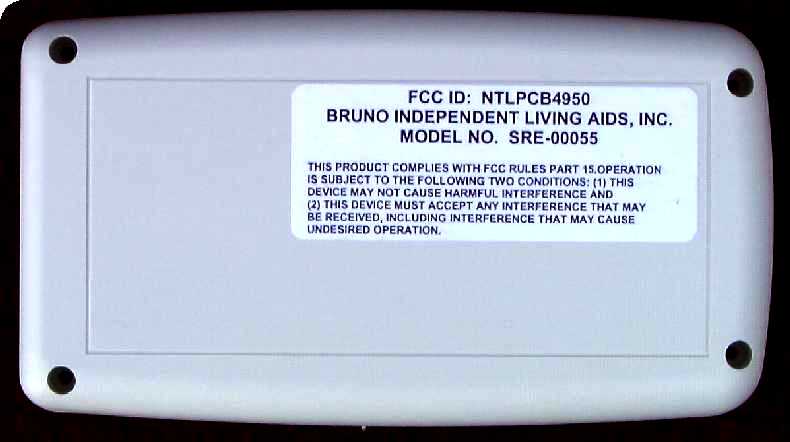
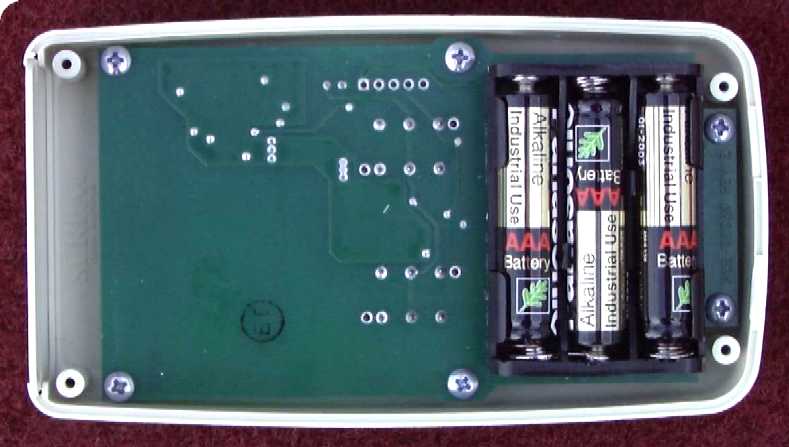
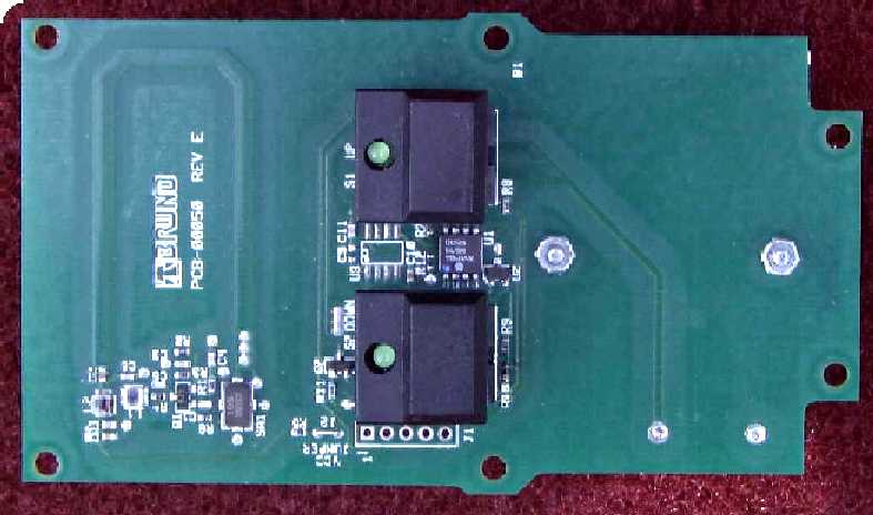
NTLPCB4950Stairway Elevator Remote Control
Bruno Independent Living Aids Inc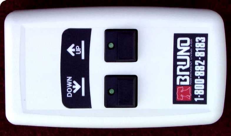
Click to zoom
Application Details
- Equipment Class
- DSC - Part 15 Security/Remote Control Transmitter
- Date of Grant
- Oct 14, 1998
- Application Purpose
- Original Equipment
- Date of Application
- Aug 09, 1998
- Equipment Note
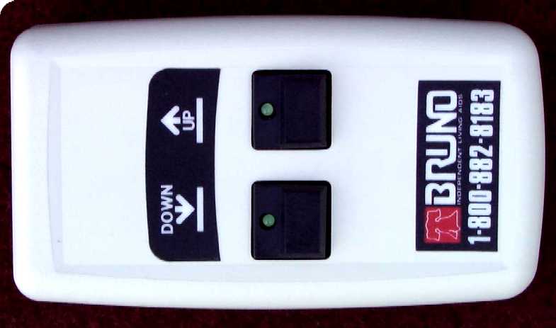
- Stairway Elevator Remote Control
- Frequency Range
- 317.90000000 - 318.10000000
- Country
- United States
Documents & Files
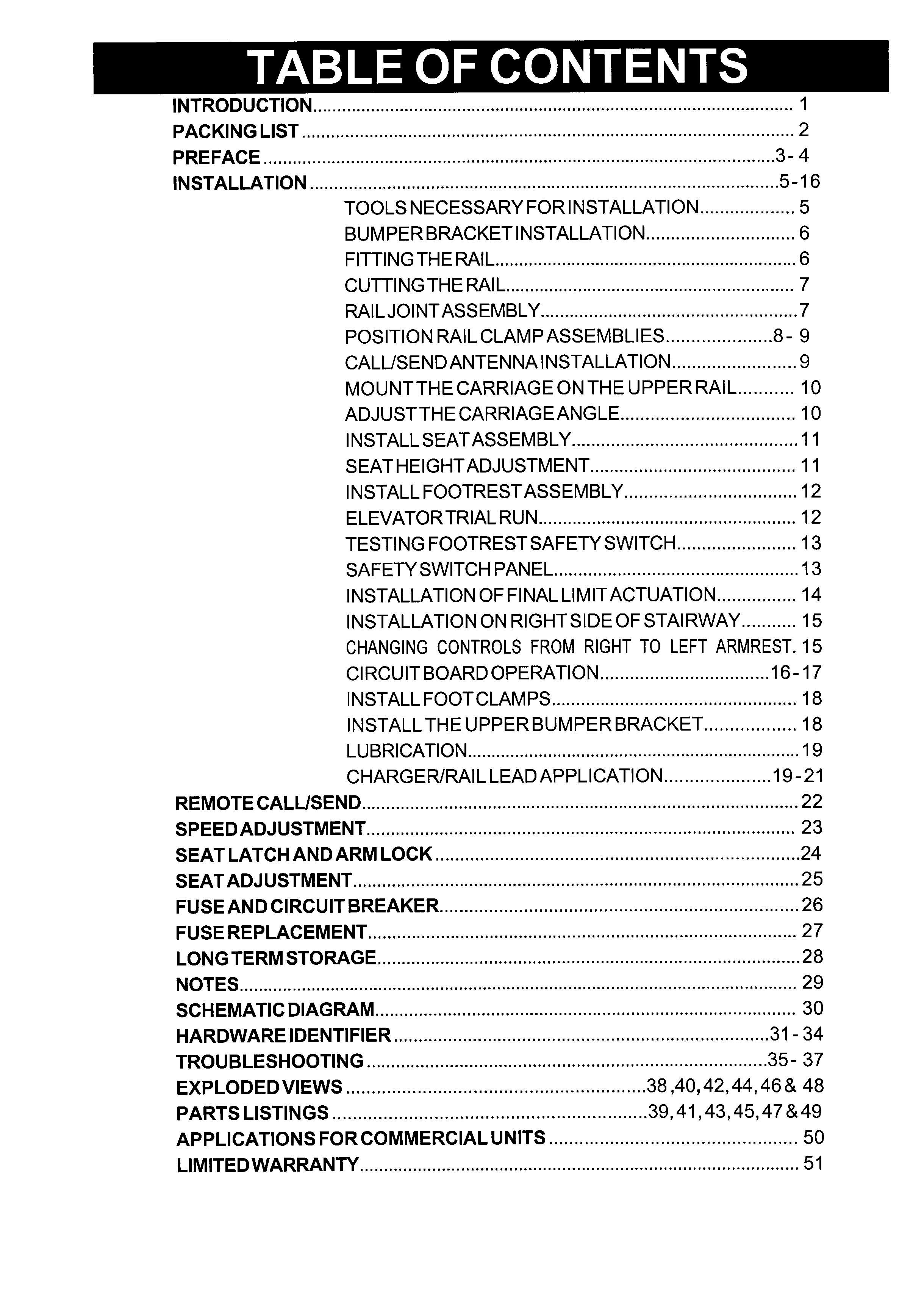
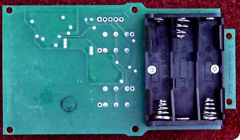
Document Text
Text extracted from the exhibit documents filed with the FCC. Open a document above to read the original.
Users Manual
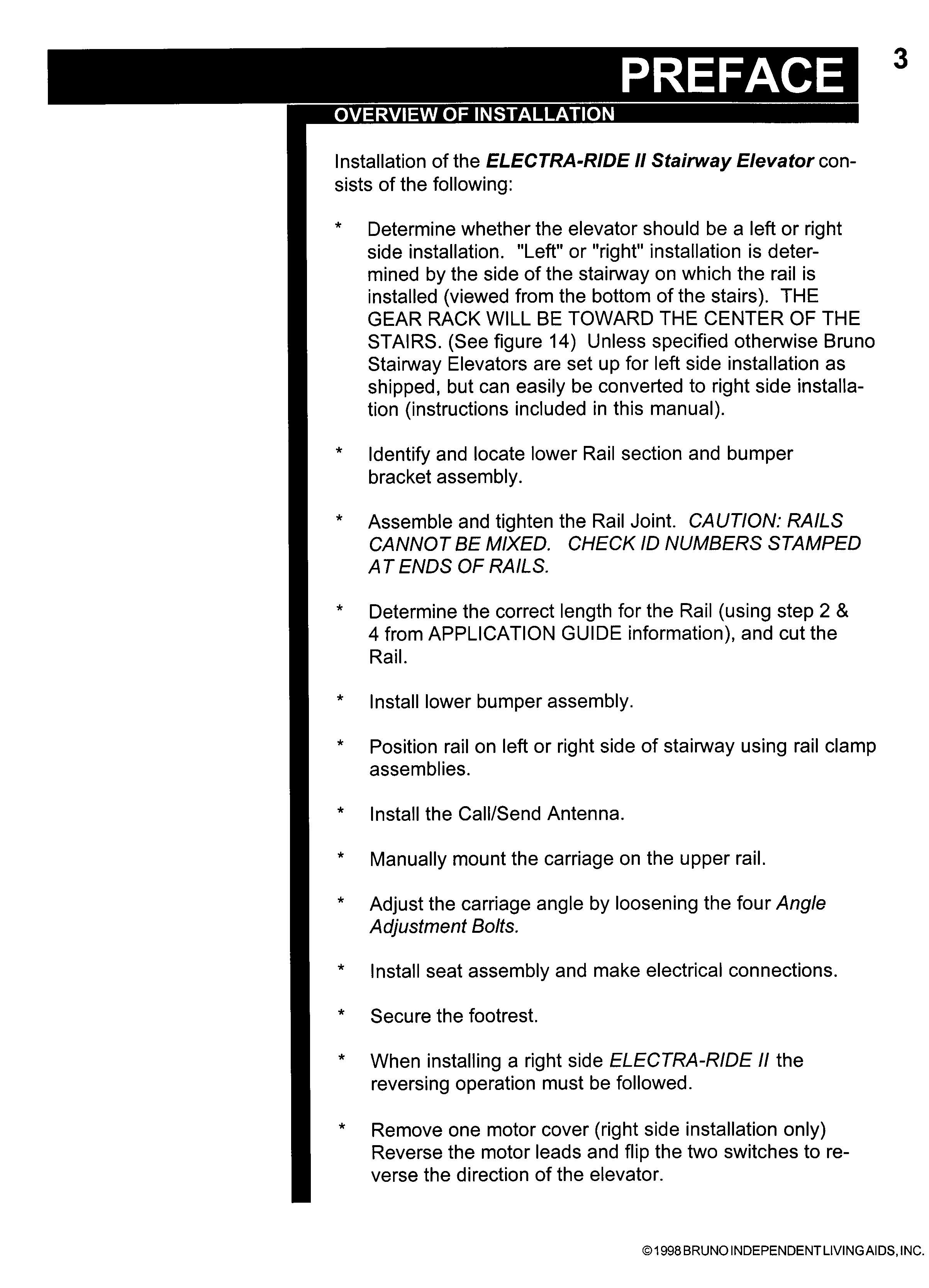
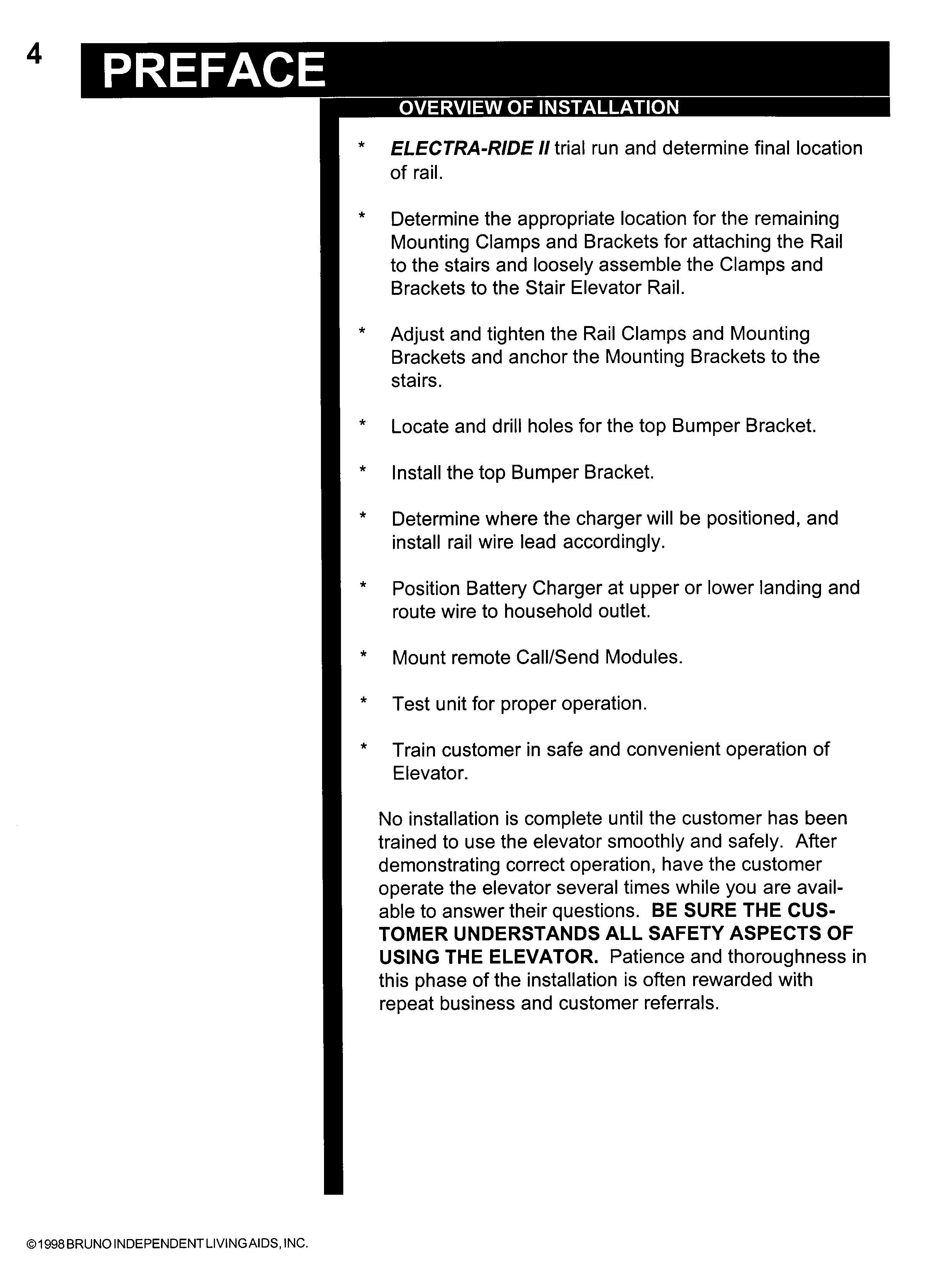
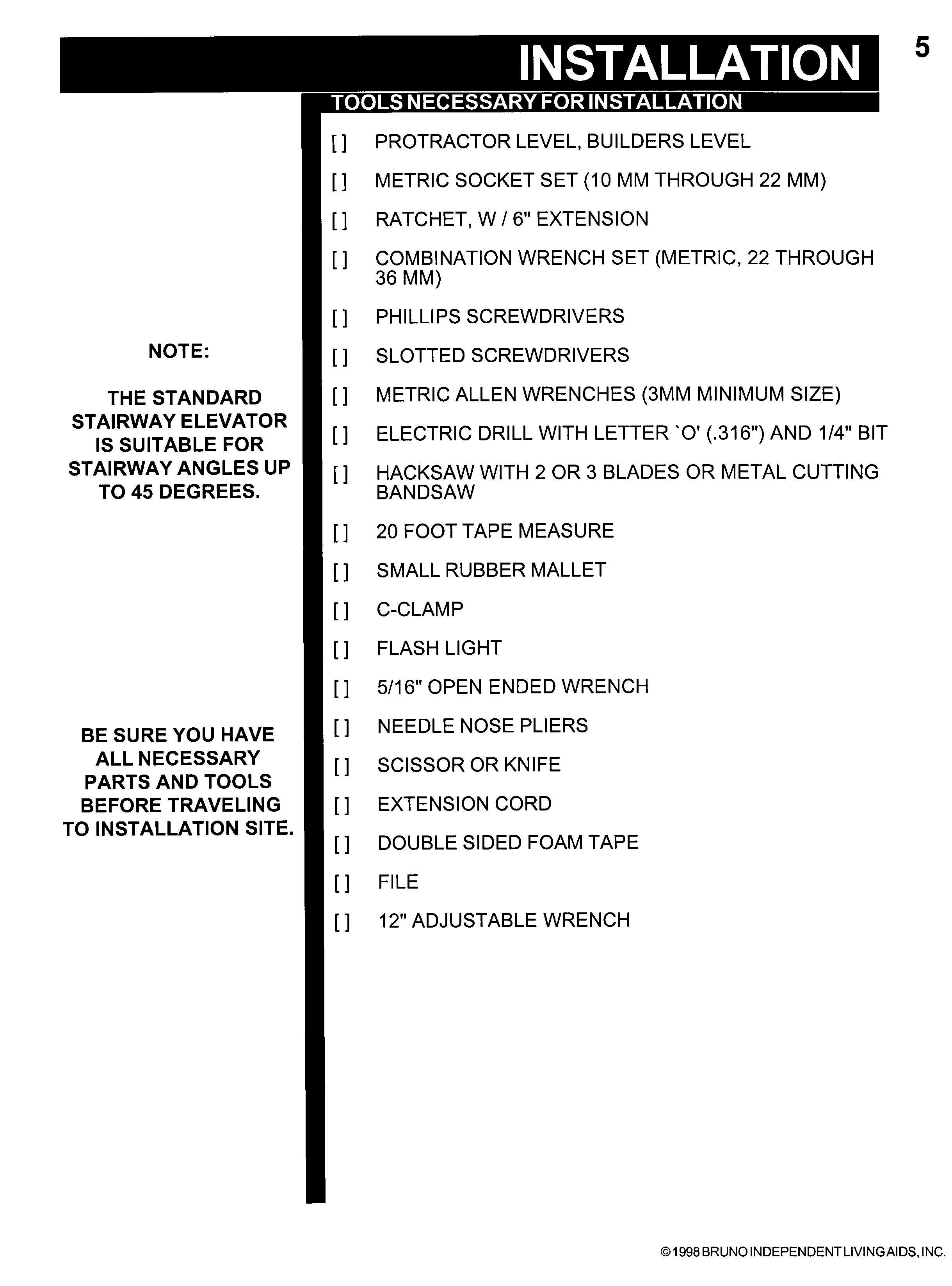
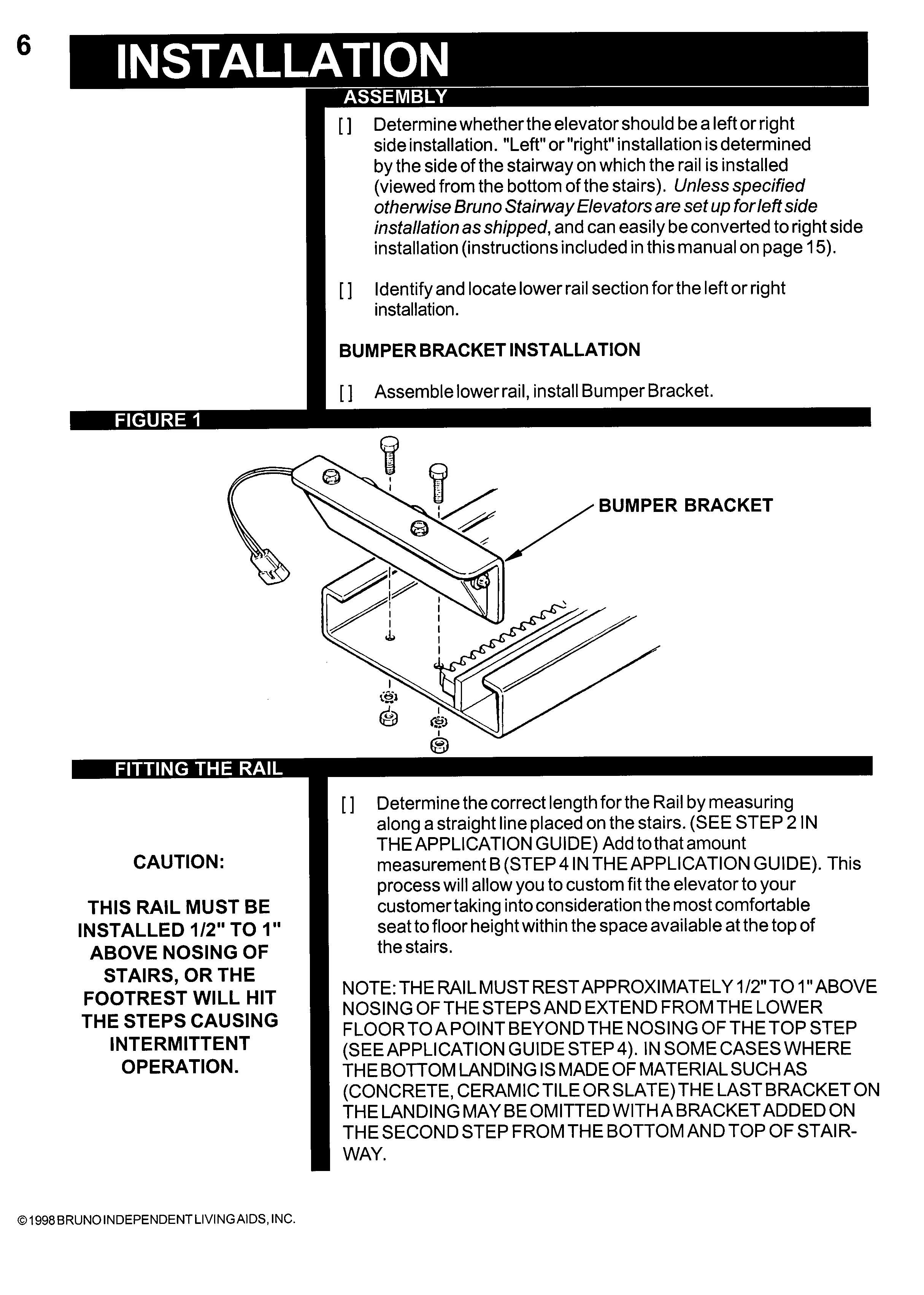
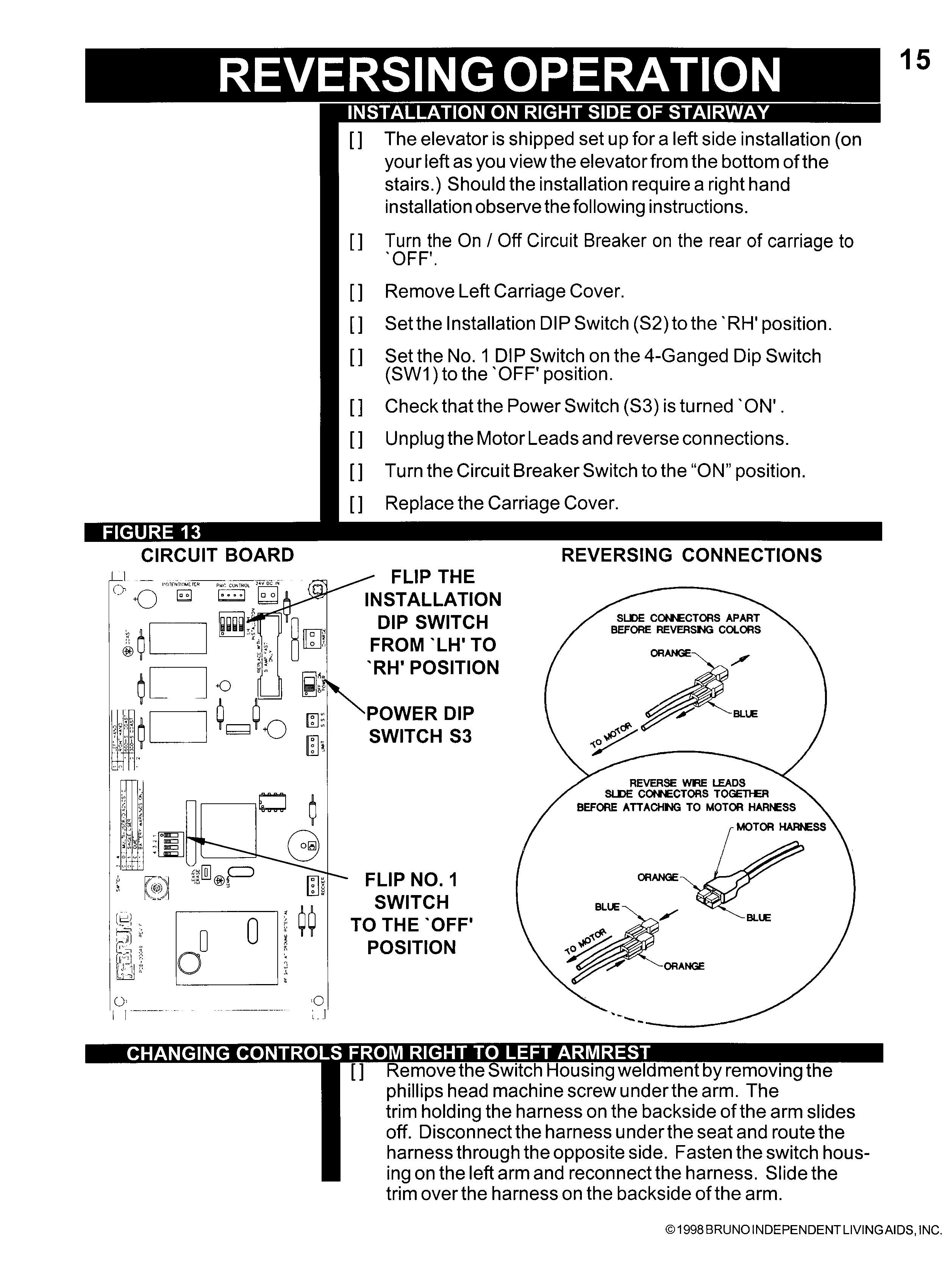
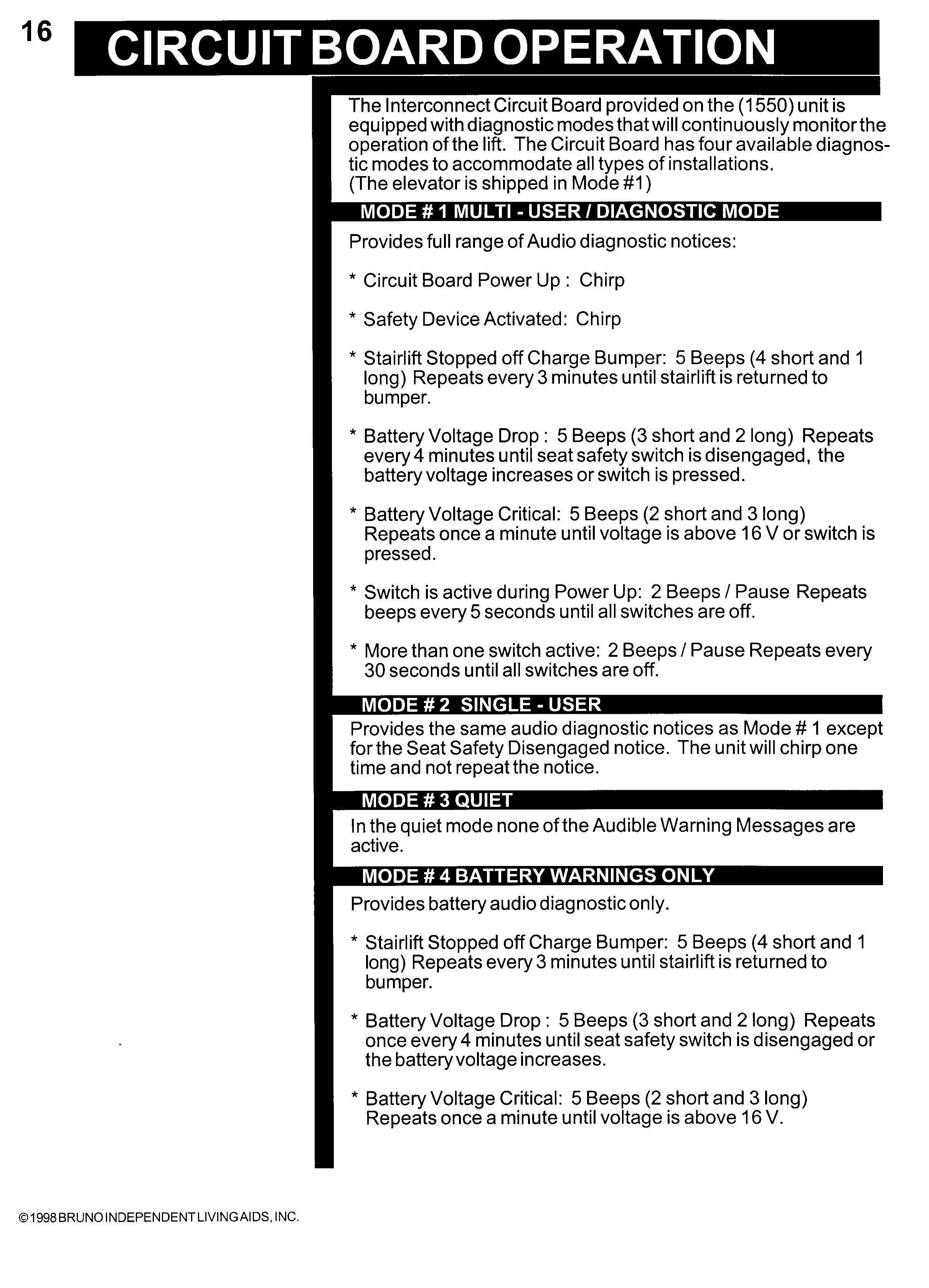
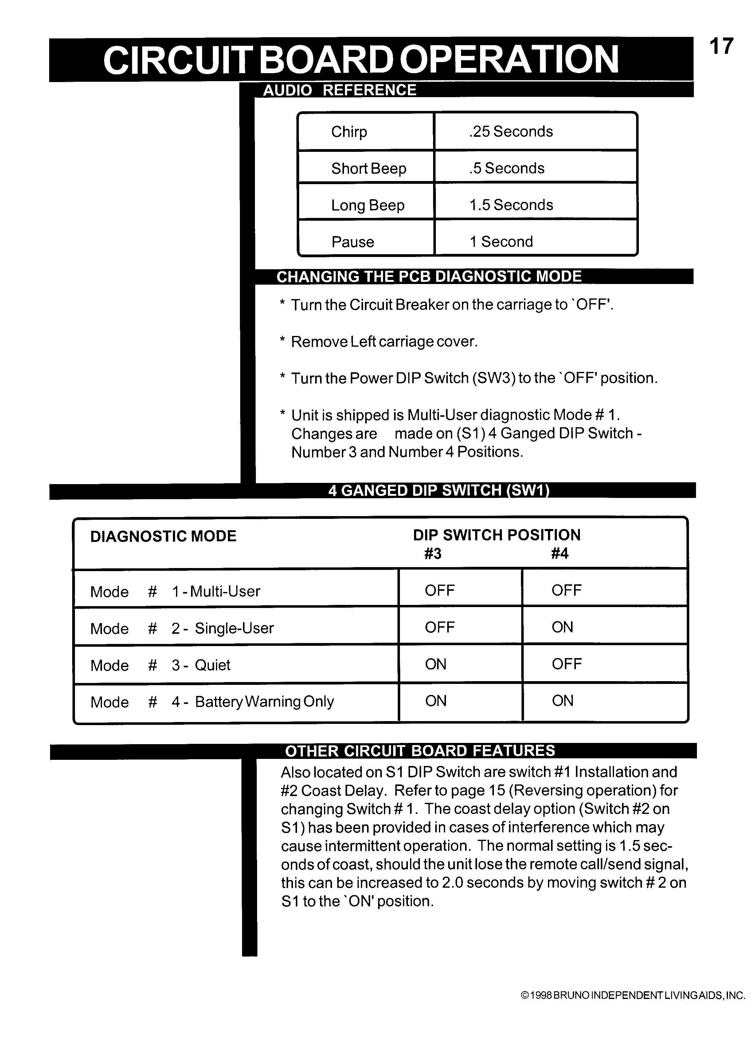
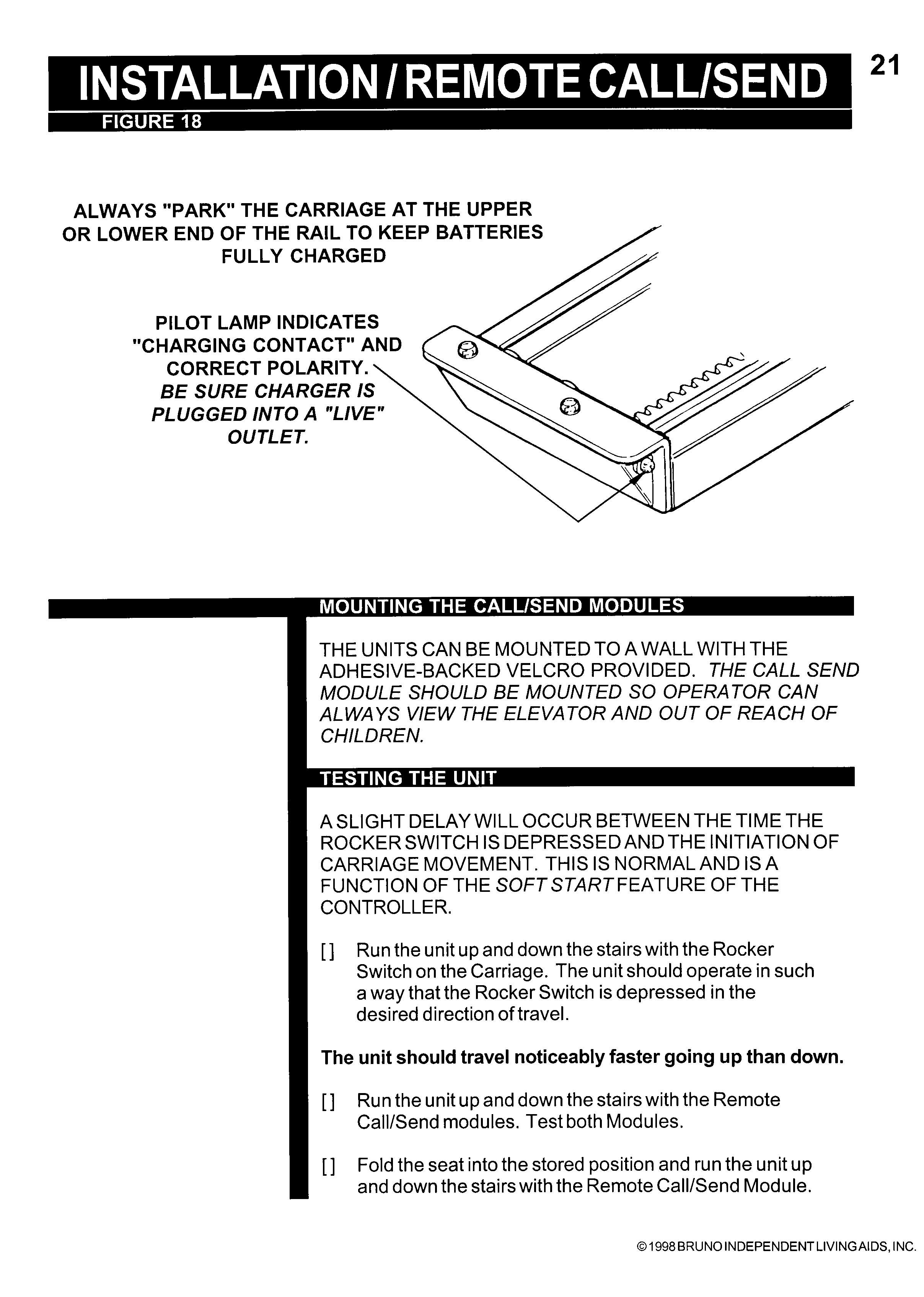
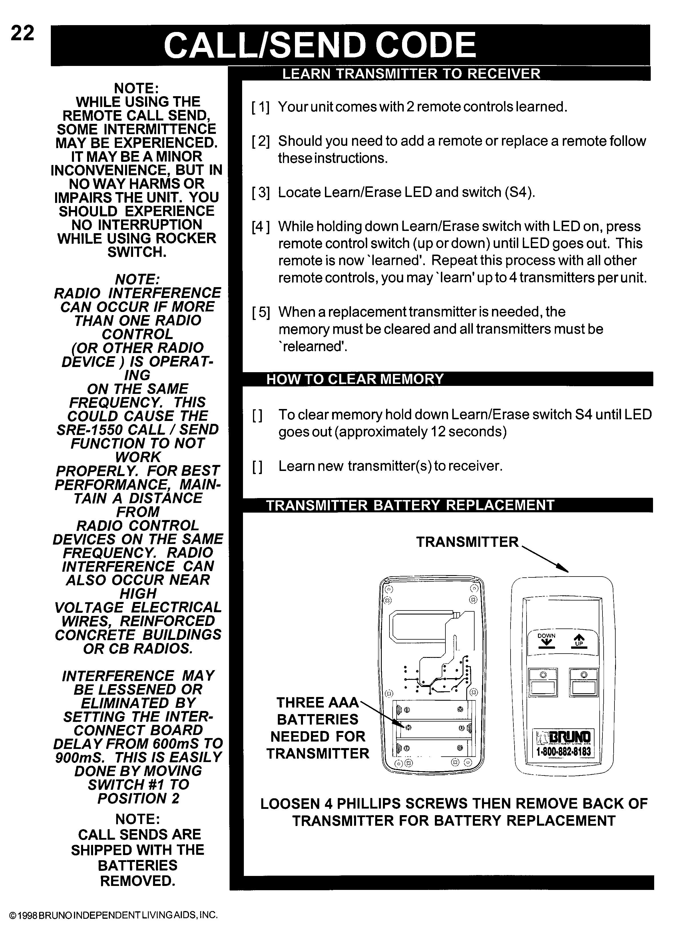
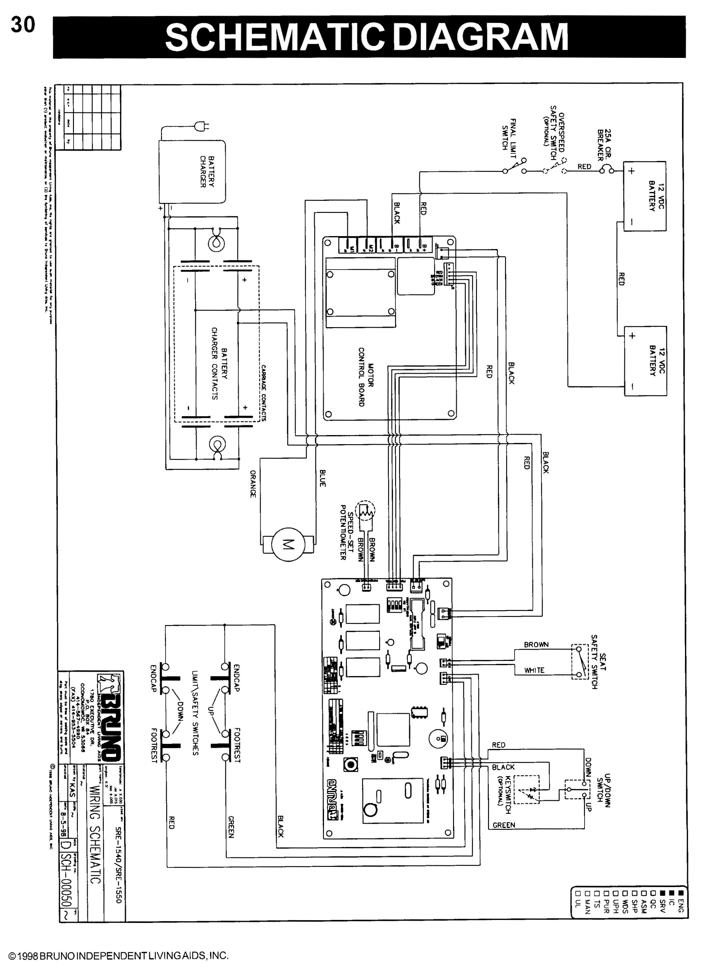
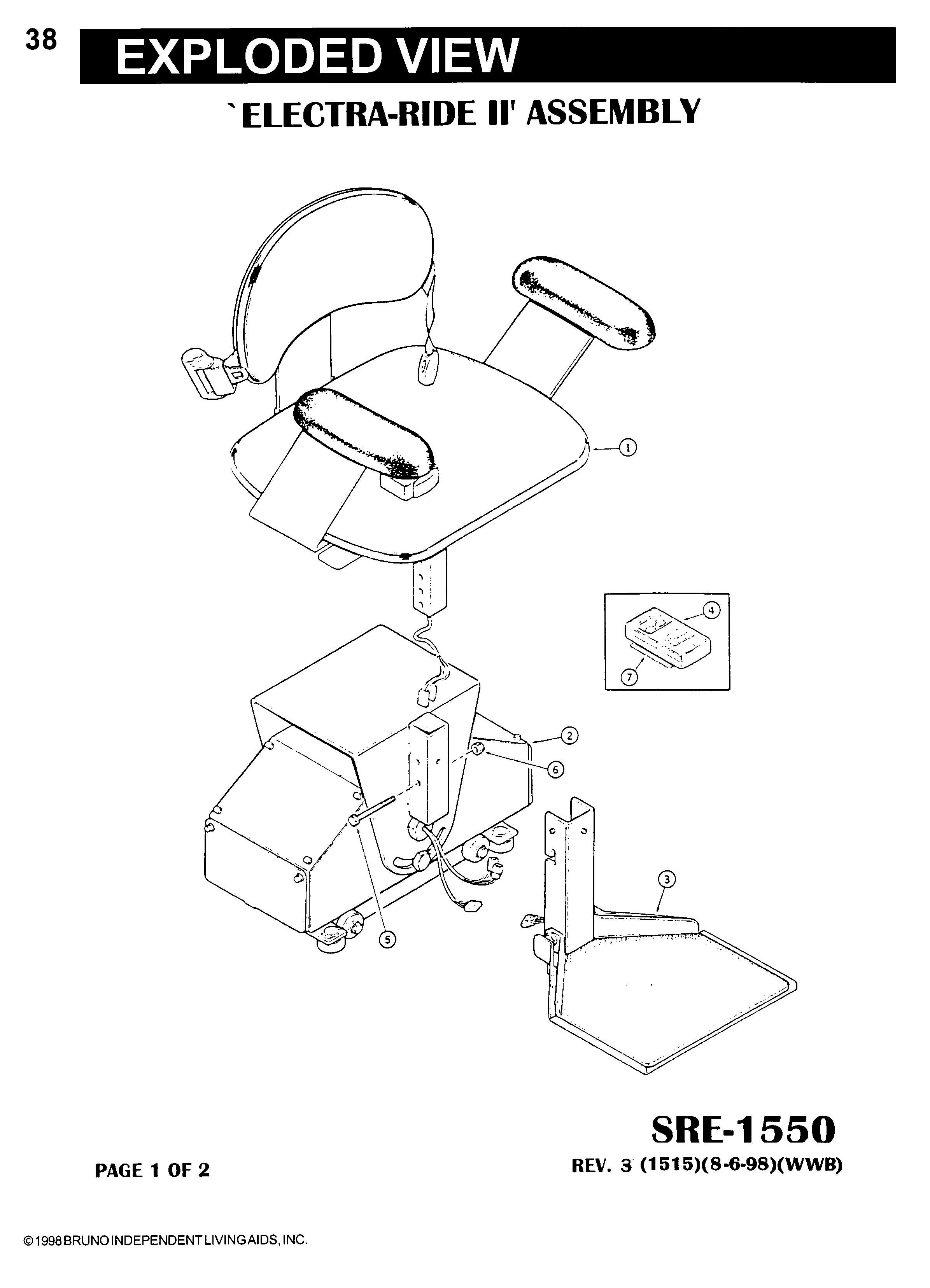
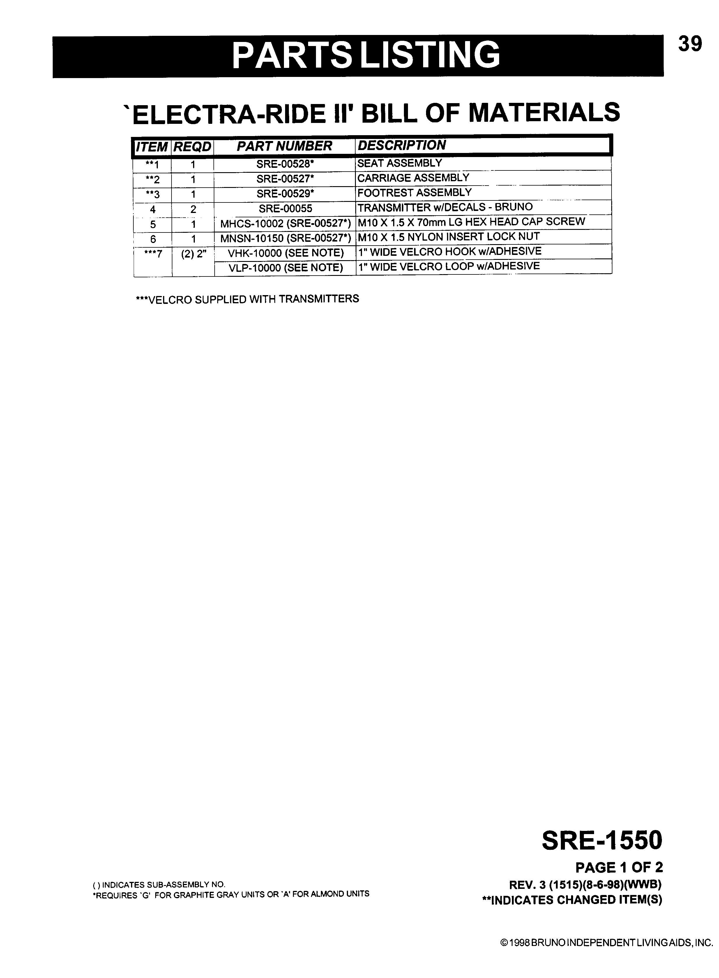
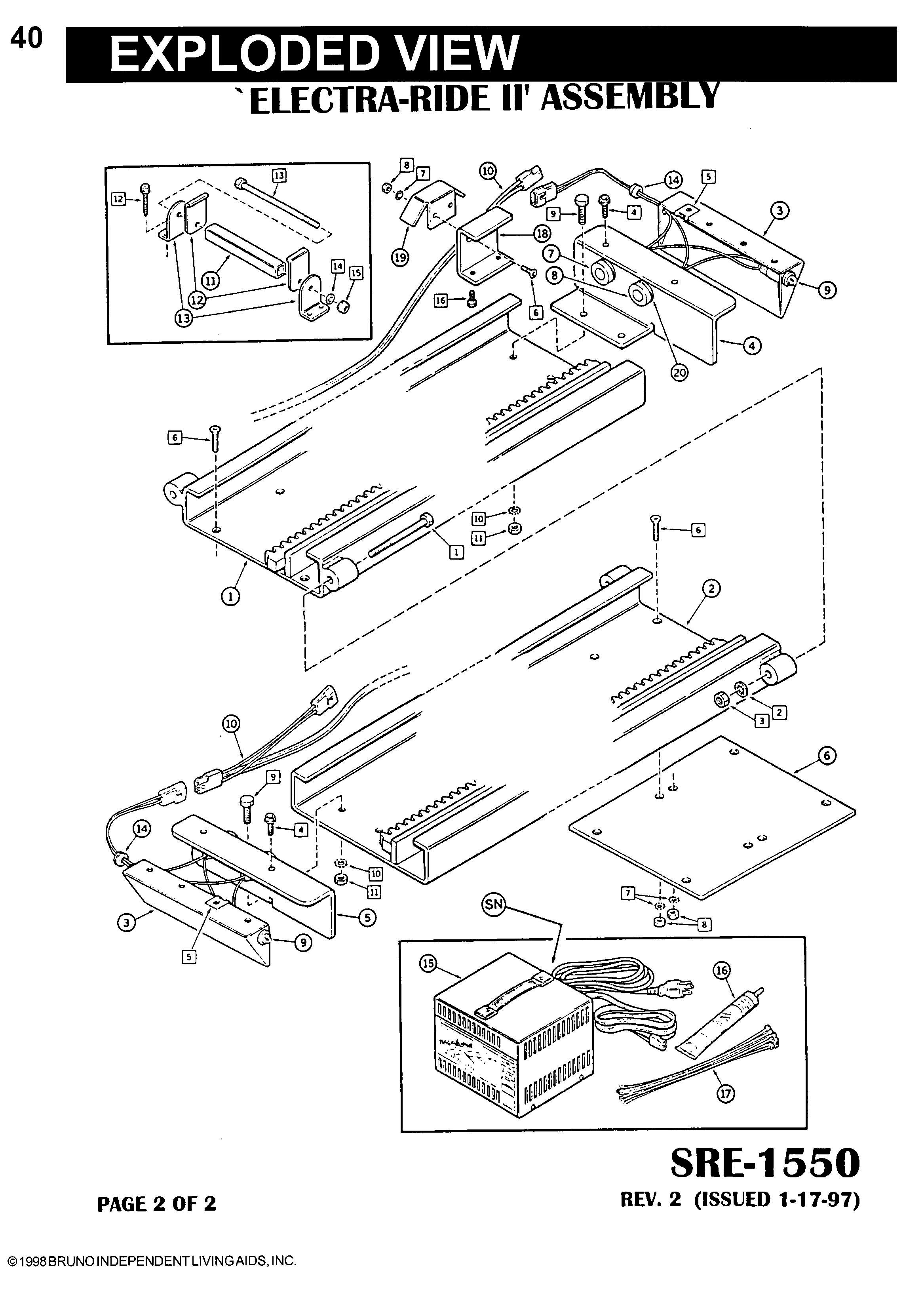
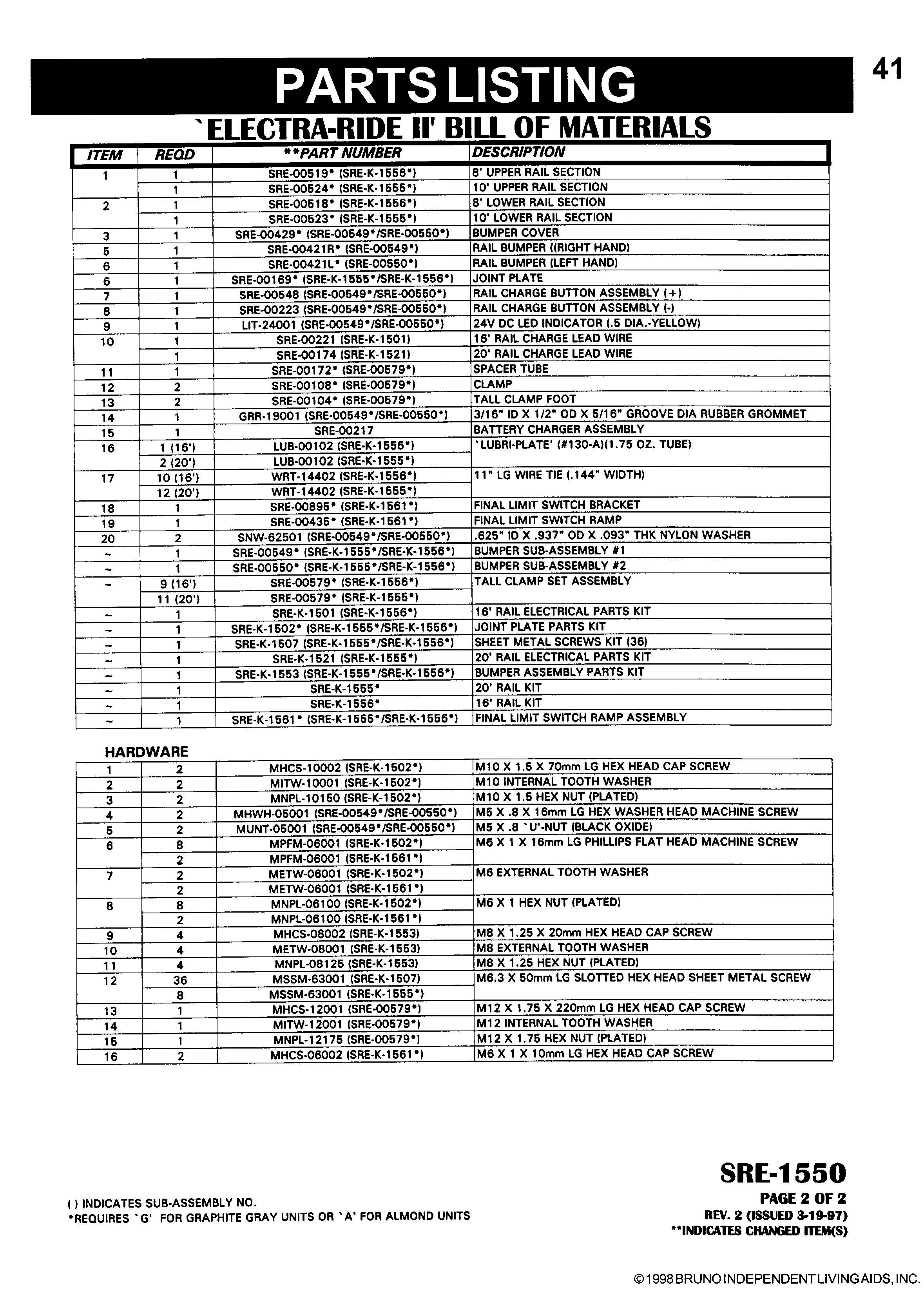
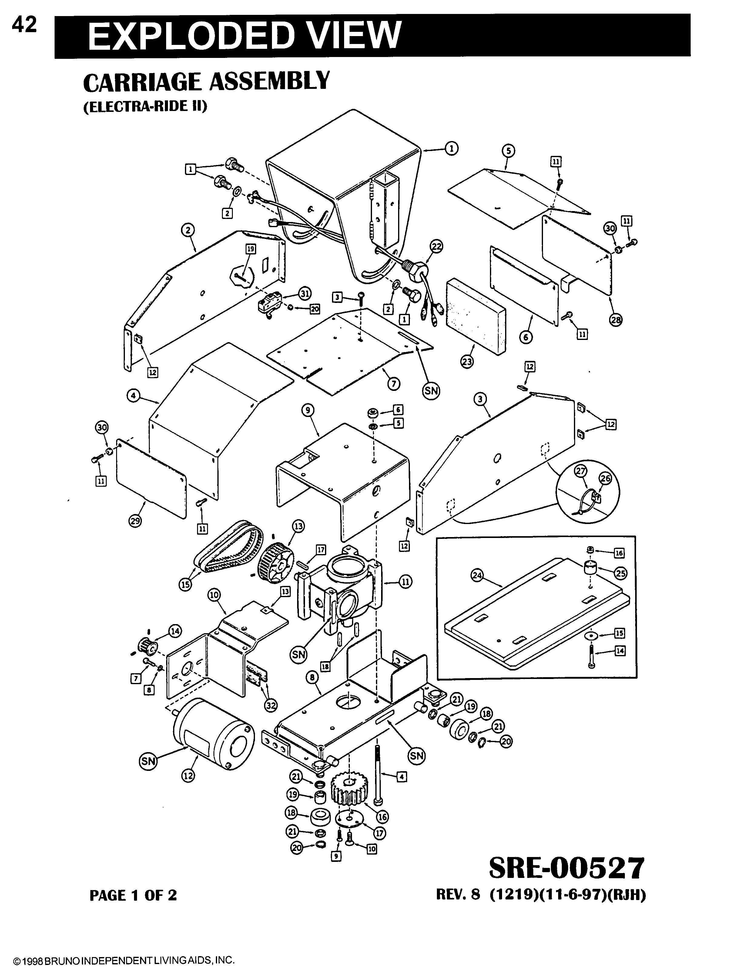
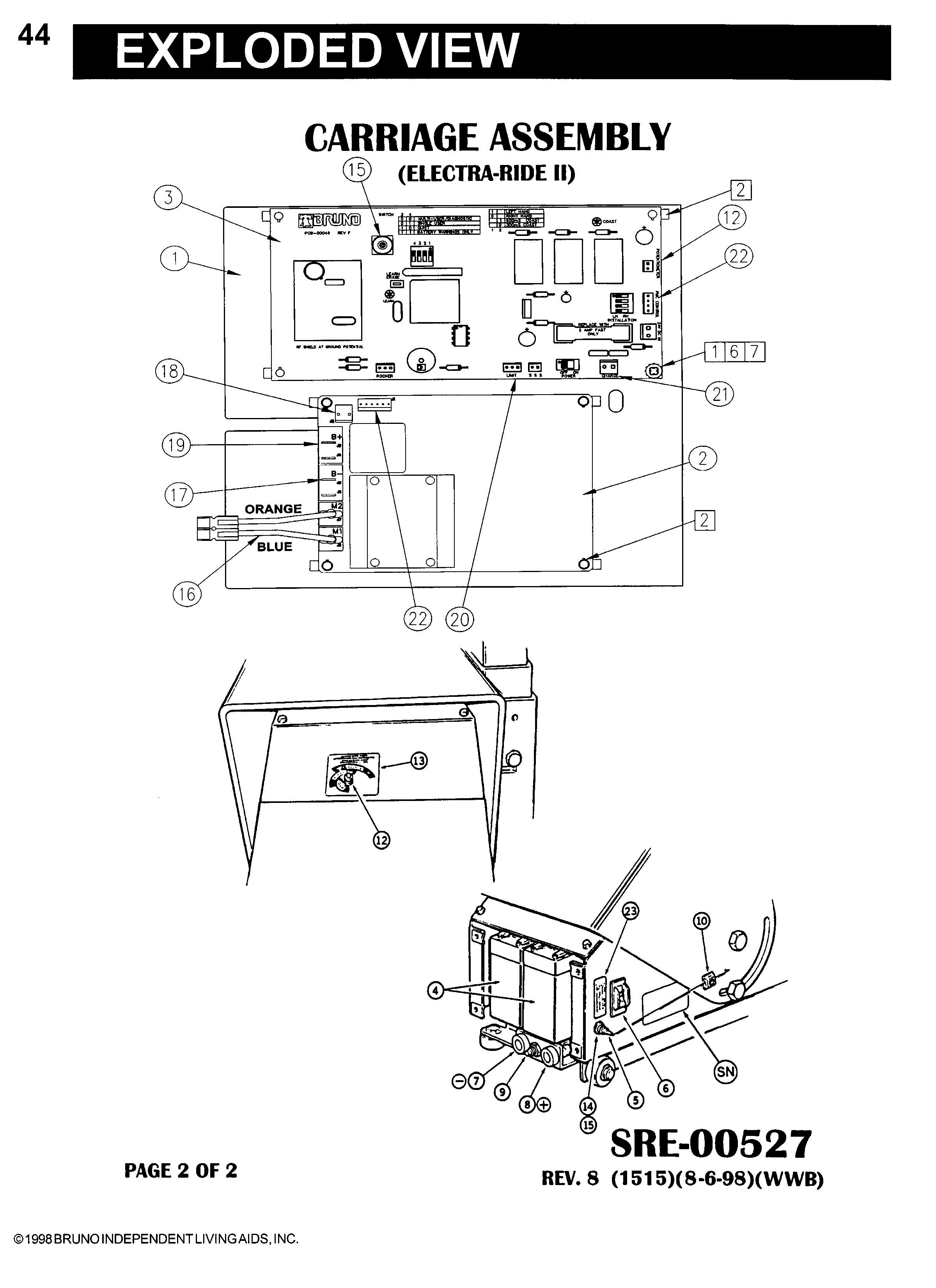
© 1998 BRUNO INDEPENDENT LIVING AIDS, INC. 1 THANK YOU FOR PURCHASING AN SRE-1550 ELECTRA-RIDE II STAIRWAY ELEVATOR. BE SURE TO CHECK CARTON CONTENTS FOR SHIPPING DAMAGE AS SOON AS THEY ARE RECEIVED. ALSO, CHECK THE CARTON CONTENTS AGAINST THE PACKING LIST (PAGE 2 OF THIS MANUAL) BEFORE BEGINNING THE INSTALLATION AND REPORT ANY DISCREPANCIES TO BRUNO INDEPENDENT LIVING AIDS IMMEDIATELY. READING THROUGH THE INSTALLATION MANUAL BEFORE INSTALLING THIS UNIT WILL ENABLE YOU TO INSTALL THE ELEVATOR MORE QUICKLY AND WILL HELP YOU AVOID THE FRUSTRATION OF GETTING TO THE JOB SITE ONLY TO DISCOVER THAT YOU ARE MISSING A CRITICAL TOOL OR PIECE OF EQUIPMENT. REVISED 08-10-98 NOTE: MATERIAL DATA SAFETY SHEET(S) ON MATERIALS USED ON THIS UNIT CAN BE REQUESTED THROUGH OUR TECHNICAL SERVICE DEPARTMENT © 1998 BRUNO INDEPENDENT LIVING AIDS, INC. 2 The ELECTRA-RIDE II is shipped in 5 cartons. Check the contents of the cartons to be sure you have all of the components before begin- ning an installation. Check the carton contents for shipping damage upon receipt. Dam- age claims must be filed by the Dealer, not the Manufacturer. Bruno Independent Living Aids cannot be responsible for shipping damage. CARTON 1 [ ]1 EA.COMPLETE CARRIAGE ASSEMBLY [ ]2 EA. BUMPER ASSEMBLIES [ ]1 EA.SRE-K-1553 BUMPER ASSEMBLY. PARTS KIT 4 EA.M8 EXT. TOOTH WASHER 4 EA.M8 X 1.25 X 20mm LG. HEX HD. CAP SCREW 4 EA.M8 X 1.25 METRIC HEX NUT (PLATED) CARTON 2 [ ]1 EA.FOOTREST ASSEMBLY [ ]8 EA.RAIL CLAMP ASSEMBLIES [ ]1 EA.BATTERY CHARGER [ ]2 EA.CALL / SEND TRANSMITTERS [ ]32 EA. (16' RAIL) 40 EA. (20' RAIL) SHEET METAL SCREWS (M 6.3 X 50 MM) [ ]1 EA.SRE-K-1501 ELEC. PARTS KIT [ ]1 EA.CHARGER HOOKUP WIRE HARNESS [ ]1 EA.FUSE (AGC 5) [ ]1 EA. *WHITE LITHIUM GREASE (16' RAIL), 2 EA. (20 ' RAIL) [ ]10 EA. WIRE TIES CARTON 3 [ ]1 EA.SEAT ASSEMBLY [ ]0 EA.(16' RAIL), 2 EA. (20' RAIL), [__] EA. (CUSTOM RAIL) CLAMP SETS CARTON 4 [ ]1 EA.RAIL SECTION CARTON 5 [ ]1 EA.RAIL SECTION [ ]1 EA.JOINT PLATE [ ]1 EA.SRE-K-1502 HARDWARE KIT (JOINT PLATE) [ ]8 EA.M6 X 16 FLAT HEAD SCREWS [ ]8 EA.M6 HEX NUTS PACKING LIST *MSDS (MATERIAL SAFETY DATA SHEET) AVAILABLE FROM BRUNO UPON REQUEST CONTACT SERVICE DEPARTMENT © 1998 BRUNO INDEPENDENT LIVING AIDS, INC. 3 PREFACE OVERVIEW OF INSTALLATION Installation of the ELECTRA-RIDE II Stairway Elevator con- sists of the following: *Determine whether the elevator should be a left or right side installation. "Left" or "right" installation is deter- mined by the side of the stairway on which the rail is installed (viewed from the bottom of the stairs). THE GEAR RACK WILL BE TOWARD THE CENTER OF THE STAIRS. (See figure 14) Unless specified otherwise Bruno Stairway Elevators are set up for left side installation as shipped, but can easily be converted to right side installa- tion (instructions included in this manual). *Identify and locate lower Rail section and bumper bracket assembly. *Assemble and tighten the Rail Joint. CAUTION: RAILS CANNOT BE MIXED. CHECK ID NUMBERS STAMPED AT ENDS OF RAILS. *Determine the correct length for the Rail (using step 2 & 4 from APPLICATION GUIDE information), and cut the Rail. *Install lower bumper assembly. *Position rail on left or right side of stairway using rail clamp assemblies. *Install the Call/Send Antenna. *Manually mount the carriage on the upper rail. *Adjust the carriage angle by loosening the four Angle Adjustment Bolts. *Install seat assembly and make electrical connections. *Secure the footrest. *When installing a right side ELECTRA-RIDE IIthe reversing operation must be followed. *Remove one motor cover (right side installation only) Reverse the motor leads and flip the two switches to re- verse the direction of the elevator. © 1998 BRUNO INDEPENDENT LIVING AIDS, INC. 4 PREFACE *ELECTRA-RIDE II trial run and determine final location of rail. *Determine the appropriate location for the remaining Mounting Clamps and Brackets for attaching the Rail to the stairs and loosely assemble the Clamps and Brackets to the Stair Elevator Rail. *Adjust and tighten the Rail Clamps and Mounting Brackets and anchor the Mounting Brackets to the stairs. *Locate and drill holes for the top Bumper Bracket. *Install the top Bumper Bracket. *Determine where the charger will be positioned, and install rail wire lead accordingly. *Position Battery Charger at upper or lower landing and route wire to household outlet. *Mount remote Call/Send Modules. *Test unit for proper operation. *Train customer in safe and convenient operation of Elevator. No installation is complete until the customer has been trained to use the elevator smoothly and safely. After demonstrating correct operation, have the customer operate the elevator several times while you are avail- able to answer their questions. BE SURE THE CUS- TOMER UNDERSTANDS ALL SAFETY ASPECTS OF USING THE ELEVATOR. Patience and thoroughness in this phase of the installation is often rewarded with repeat business and customer referrals. OVERVIEW OF INSTALLATION © 1998 BRUNO INDEPENDENT LIVING AIDS, INC. 5 NOTE: THE STANDARD STAIRWAY ELEVATOR IS SUITABLE FOR STAIRWAY ANGLES UP TO 45 DEGREES. BE SURE YOU HAVE ALL NECESSARY PARTS AND TOOLS BEFORE TRAVELING TO INSTALLATION SITE. INSTALLATION TOOLS NECESSARY FOR INSTALLATION [ ]PROTRACTOR LEVEL, BUILDERS LEVEL [ ]METRIC SOCKET SET (10 MM THROUGH 22 MM) [ ]RATCHET, W / 6" EXTENSION [ ]COMBINATION WRENCH SET (METRIC, 22 THROUGH 36 MM) [ ]PHILLIPS SCREWDRIVERS [ ]SLOTTED SCREWDRIVERS [ ]METRIC ALLEN WRENCHES (3MM MINIMUM SIZE) [ ]ELECTRIC DRILL WITH LETTER `O' (.316") AND 1/4" BIT [ ]HACKSAW WITH 2 OR 3 BLADES OR METAL CUTTING BANDSAW [ ]20 FOOT TAPE MEASURE [ ]SMALL RUBBER MALLET [ ]C-CLAMP [ ]FLASH LIGHT [ ]5/16" OPEN ENDED WRENCH [ ]NEEDLE NOSE PLIERS [ ]SCISSOR OR KNIFE [ ]EXTENSION CORD [ ]DOUBLE SIDED FOAM TAPE [ ]FILE [ ]12" ADJUSTABLE WRENCH © 1998 BRUNO INDEPENDENT LIVING AIDS, INC. 6 INSTALLATION ASSEMBLY FIGURE 1 FITTING THE RAIL [ ]Determine whether the elevator should be a left or right side…
Text truncated - open the document above for the full version.
Attestation Statements
C:\WINDOWS\AZTPNP.EXE /A:ON /IDE:OFF @call c:\wsybset.bat SET BLASTER=A220 I5 D1 T4
Attestation Statements
1780 Executive Drive PO Box 84 Oconomowoc, WI. 53066 FCC AUTHORIZATION DATE: August 8, 1998 TIME: 12:15 pm TO: FCC Authorization & Evaluation Division 7435 Oakland Mills Road Columbia, MD 21045-0429 FROM: William W. Belson III PHONE: (414) 953-5359 (Direct Line) Director of Engineering FAX: (414) 953-5504 APPLICANT: Bruno Independent Living Aids, Inc. E-MAIL: [email protected] Dear Ladies and/or Gentlemen, I appoint Kenneth L. Boston and or James Blaha of L.S. Compliance Inc., to act as an agent in the preparation under Part 15 of the rules and Regulations of the Federal Communications Commission. I certify that the exhibitions properly describe the device being submitted under this application and will implement any changes described in the test report. The labels described will be affixed to each item. The following statement is required by the Federal Communications Commission: By checking Yes, the applicant certifies that, in the case of an individual applicant, he or she is not subject to a denial of federal benefits, that included FCC benefits, pursuant to section 5301 of the Anti-Drug Abuse Act of 1988, 21 U.S.C. 853(a), or, in the case of a non-individual applicant (e.g. corporation, partnership, or other unincorporated association), no party to the application is subject to a denial of federal benefits, that includes FCC benefits, pursuant to that section. ___X___ YES______ NO Dated this 8 th day of August, 1998 Agency agreement expiration date (if any): By: William W. Belson III Title: Director of Engineering, Bruno Independent Living Aids, Inc. Phone: 414-953-5359
Block Diagram
BRUNO Independent Living Aids Form 731 Confirmation Number: EA91327 FCC ID: NTL-PCB4950 Transmitter Block Diagram Preliminary Specifications • Carrier Frequency: 318 MHz • Operational Voltage: 4.5 ∼ 2.7 volts • Current Consumption: < 10 mA (peak) • Sleep Mode Current: < 10 uA • Antenna: 0.75" x 1.5" x 0.10" PCB loop • Baud Rate: 1000 bps • Modulation Format: Return-to-Zero Amplitude Shift Keying (ASK) • Frequency Stability: ±100 kHz Down 4-Bit Microprocessor EEPROM Low Battery Detector SAW Stabilized Oscillator/PA PCB Loop Antenna Up Remote Key Switch 3 x AAA Battery
Cover Letter(s)
1780 Executive Drive PO Box 84 Oconomowoc, WI. 53066 FCC AUTHORIZATION DATE: August 8, 1998 TIME: 12:15 pm TO: FCC Authorization & Evaluation Division 7435 Oakland Mills Road Columbia, MD 21045-0429 FROM: William W. Belson III PHONE: (414) 953-5359 (Direct Line) Director of Engineering FAX: (414) 953-5504 APPLICANT: Bruno Independent Living Aids, Inc. E-MAIL: [email protected] Dear Ladies and/or Gentlemen, I appoint Kenneth L. Boston and or James Blaha of L.S. Compliance Inc., to act as an agent in the preparation under Part 15 of the rules and Regulations of the Federal Communications Commission. I certify that the exhibitions properly describe the device being submitted under this application and will implement any changes described in the test report. The labels described will be affixed to each item. The following statement is required by the Federal Communications Commission: By checking Yes, the applicant certifies that, in the case of an individual applicant, he or she is not subject to a denial of federal benefits, that included FCC benefits, pursuant to section 5301 of the Anti-Drug Abuse Act of 1988, 21 U.S.C. 853(a), or, in the case of a non-individual applicant (e.g. corporation, partnership, or other unincorporated association), no party to the application is subject to a denial of federal benefits, that includes FCC benefits, pursuant to that section. ___X___ YES______ NO Dated this 8 th day of August, 1998 Agency agreement expiration date (if any): By: William W. Belson III Title: Director of Engineering, Bruno Independent Living Aids, Inc. Phone: 414-953-5359
Test Report
L. S. COMPLIANCE, Inc. FCC ID: NTL-PCB4950 SC-Bruno 80125a Table of Contents: SectionDescriptionPage # Exhibit 3: Description of Measurement Facilities1 Exhibit 7: Report of Measurements2 1.1Cover Page2 1.2Signature Page3 1.3Summary of Test Report4 1.4Introduction5 1.5Purpose5 1.6Radiated Emission Test Setup5 1.7Radiated Emission Test Procedure6 1.8Radiated Emission Test Equipment Utilized7 1.9Conducted Emission Measurements7 1.10Restricted Bands (Frequencies and Limits)8 1.11Photos taken during testing9 1.12Summary of Results and Conclusions11 1.13Test Equipment List12 Appendic es ASample Calculations:13 i.Calculation of Radiated Emissions Limits14 ii.Duty Cycle Correction Factor Calculation15 iii.Occupied Bandwidth Calculations16 BData Charts17 CGraphs19 L. S. COMPLIANCE, Inc. FCC ID: NTL-PCB4950 LSC-Bruno 80125 1 L. S. COMPLIANCE, Inc. FCC ID: NTL-PCB4950 LSC-Bruno 80125 2 DESCRIPTION OF MEASUREMENT FACILITIES Site on File with the FCC ID Number: 31040/SIT 1300F2 “ The site referenced above has been found to comply with the test site criteria found in ANSI C63.4-1992 and 47CFR Section 2.948.” L. S. COMPLIANCE, Inc. FCC ID: NTL-PCB4950 LSC-Bruno 80125 3 COMPLIANCE TESTING OF BRUNO INDEPENDENT LIVING AIDS REMOTE CONTROL TRANSMITTER - TEST REPORT - JULY 14, 17, AND AUGUST 4, 1998 Prepared for: Bill Belson Bruno Independent Living Aids L. S. COMPLIANCE, Inc. FCC ID: NTL-PCB4950 LSC-Bruno 80125 4 1780 Executive Drive Oconomowoc, WI 53066 L. S. COMPLIANCE, Inc. FCC ID: NTL-PCB4950 LSC-Bruno 80125 5 SIGNATURE PAGE Prepared By: Approved By: Kenneth L.Boston 12 aug 1998 Kenneth L. Boston, EMC Lab Manager Date PE #31926 Registered Professional Engineer (State of Wisconsin) L. S. COMPLIANCE, Inc. FCC ID: NTL-PCB4950 LSC-Bruno 80125 6 L. S. COMPLIANCE, Inc. FCC ID: NTL-PCB4950 LSC-Bruno 80125 7 1.3 SUMMARY OF TEST REPORT MANUFACTURER:BRUNO INDEPENDENT LIVING AIDS MODEL:Call/Send Remote Control SERIAL:621 DESCRIPTION:Low power Periodic Transmitter FREQUENCY RANGE:TRANSMITTER; 318 MHz The Bruno Call/Send Remote control was found to “meet” the radiated emission specification of Title 47 CFR FCC, Part 15, subpart C. for an intentional radiator This Remote Control device is meant to control the operation of a chair Lift which is mounted on a stairway, in order to allow an elderly or disabled person to move the lift up and down the staircase. The associated control receiver is part of this system, and subject to Notification. The receiver is the subject of a concurrent filing. L. S. COMPLIANCE, Inc. FCC ID: NTL-PCB4950 LSC-Bruno 80125 8 1.4INTRODUCTION On July 14, 17 and August 4 of 1998, a series of Radiated Emissions tests were performed on a sample model of the Bruno Call/Send Remote control product; a Remote control which operates a stairlift by means of a short burst of data transmission containing an I.D. code. These tests were performed using the test procedures outlined in ANSI C63.4-1992 for intentional radiators, and in accordance with the limits set forth in FCC Part 15.231a,b for a periodic transmitter. These tests were performed by Kenneth L. Boston, PE, of L. S. Compliance, Inc. and witnessed by Kelly Smith of Bruno Independent Living Aids. 1.5PURPOSE The above mentioned tests were performed in order to determine the compliance of the Call/Send Remote control product with limits contained in various provisions of Title 47 CFR, FCC Part 15, including: 15.20515.231b 15.209 15.231c All radiated emissions tests were performed to measure the emissions in the frequency bands described by the above sections, and to determine whether said emissions are below the limits established by the above sections. These tests were performed in accordance with the procedure described in the American National Standard for methods of measurement of Radio-Noise Emissions from Low-Voltage Electrical and Electronic Equipment in the Range of 9 kHz to 40 GHz (ANSI C63.4-1992). Another document used as reference for the EMI receiver specification was the International Special Committee on Radio Interference (CISPR) number 16-1 (1993). 1.6 RADIATED EMISSIONS TEST SETUP The test sample was operated within the 3 meter Semi-Anechoic, FCC listed chamber located at L.S. Compliance in Cedarburg, WI. The sample was placed on an 80cm high wooden pedestal, which was centered on the flush-mounted 2m diameter metal turntable. The test sample was operated on its own [new] internal battery. The test sample was configured to run in a continuous transmit mode during the 15.231c and 15.231b measurements. One test sample set to operate on the standard channel was tested as an intentional radiator, in order to determine compliance at a frequency of 318 MHz, Please refer to Section 1.11 for pictures of the test setup. L. S. COMPLIANCE, Inc. FCC ID: NTL-PCB4950 LSC-Bruno 80125 9 L. S. COMPLIANCE, Inc. FCC ID: NTL-PCB4950 LSC-Bruno 80125 10 1.7RADIATED EMISSION TEST PROCEDURE The fundamental and spurious (harmonic) emissions of the transmitter were tested for compliance to Title 47 CFR, FCC Part 15.231b limits for periodic devices. For the calculations used to determine the limits applicable for the test sample, refer to Appendix A. These limits are expressed in decibels (dB) above 1 microvolt per meter (μV/m). The sample was tested from the lowest frequency generated by the transmitter (without going below 9 kHz) to the 10th harmonic of the fundamental frequency generated by the device. The appropriate limits were also observed when the fundamental or spurious signals were located within any of the restricted bands as described in Part 15.205a. These frequencies, and their associated limits, are referenced in Section 7.10. The sample was placed on a nonconductive (wooden) pedestal in the 3 Meter chamber and the antenna mast was placed such that the antenna was 3m from the test object. A biconical antenna or tuned dipole was used to measure emissions from 30 to 200 MHz, a log periodic or tuned dipole was used to measure emissions from 20…
Text truncated - open the document above for the full version.
Test Report
L. S. COMPLIANCE, Inc. FCC ID: NTL-PCB4950 LSC-Bruno 80125 1 Corrected transmitter plot for Bruno remote transmitter RE: CORRECTED DATA SUBMISSION: The plot submitted in the report for the Bruno remote transmitter, ID # NTL-PCB4950 was created before the final power adjustment had been made on the transmitter board. The tabular data found on page 23 was taken as final values, after power was set by varying a resistor size by one standard value and entered into the report. The plot shown on page 25 was inadvertently left in the report; said plot having been created before the final power level had been set. The schematic enclosed with the filing reflects the final selection of this resistor value. (R2=220 ohms) The plot enclosed shows the same transmitter re-tested, using new batteries. Also checked was the frequency range 30-3200 MHz, with no change in the earlier provided data noted, except for the occupied bandwidth. This was seen to be somewhat wider than that shown on the original plot, but still well within the allowed bandwidth. (440 kHz on sept. 8 th vs. 300 kHz earlier; bandwidth allowed : up to 795 kHz) Therefore a fresh plot of Occupied Bandwidth is also supplied. These materials are supplied in response to a telephone conversation on September 2 with the FCC engineering office in Columbia, MD GRAPHS FOLLOW L. S. COMPLIANCE, Inc. FCC ID: NTL-PCB4950 LSC-Bruno 80125 2 318 MHz Remote Control, emissions below 1 GHz, horizontal polarity L. S. COMPLIANCE, Inc. FCC ID: NTL-PCB4950 LSC-Bruno 80125 3 318 MHz Remote Control, occupied bandwidth L. S. COMPLIANCE, Inc. FCC ID: NTL-PCB4950 LSC-Bruno 80125 4
Contact Information
Applicant
Bill Belson(Director, Engineering)
414 - 953 - 5314Fax: 414 - 953 - 5314
Technical Contact
Bruno Independent Living AidsKelly Smith
[email protected]414 - 953 - 5314
1780 Executive Drive · Oconomowoc, Wisconsin · United States
Non-Technical Contact
L. S. Compliance, Inc.Jim Blaha
Test Firm
LS Research, LLCRyan Urness
Technical Specifications
| # | Rule Parts | Frequency Range | Power Output | Tolerance |
|---|---|---|---|---|
| 1 | 15C | 317.9 MHz - 318.1 MHz | - | % |