NUGCR0010Marine Public Safety Transceiver
Zionsville Engineering Inc
Click to zoom
Application Details
- Equipment Class
- TNF - Licensed Non-Broadcast Transmitter Held to Face
- Date of Grant
- Feb 29, 2000
- Application Purpose
- Original Equipment
- Date of Application
- Nov 17, 1999
- Equipment Note
- Marine Public Safety Transceiver
- Frequency Range
- 150.00000000 - 174.00000000
- Company
- Zionsville Engineering Inc
- Country
- United States
Documents & Files
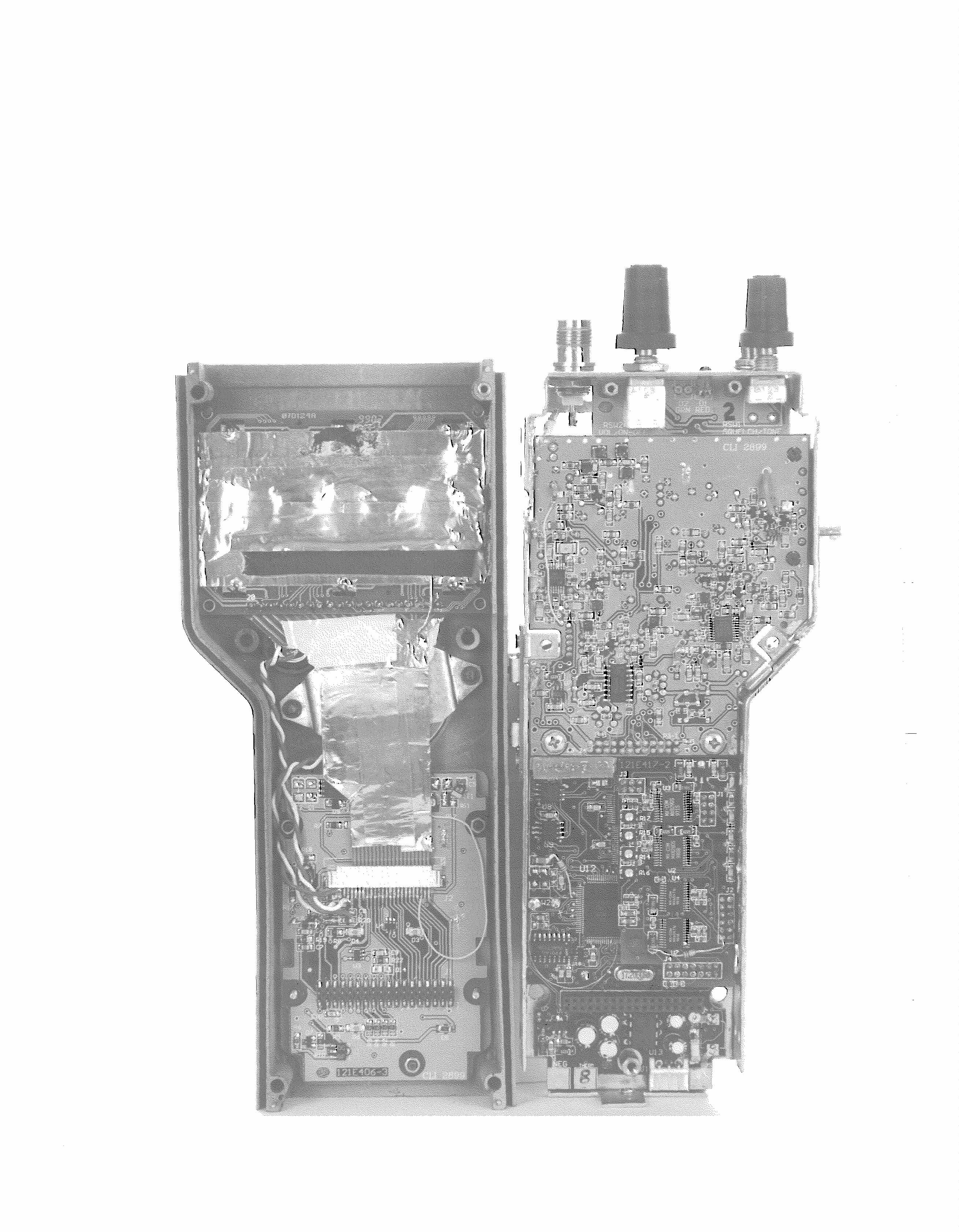
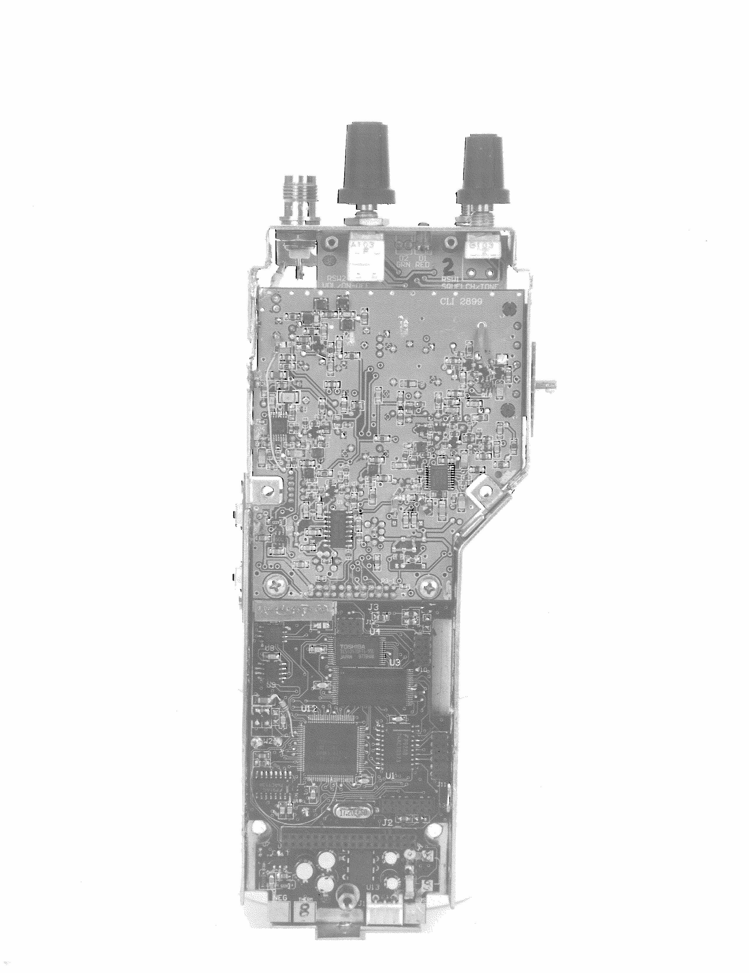
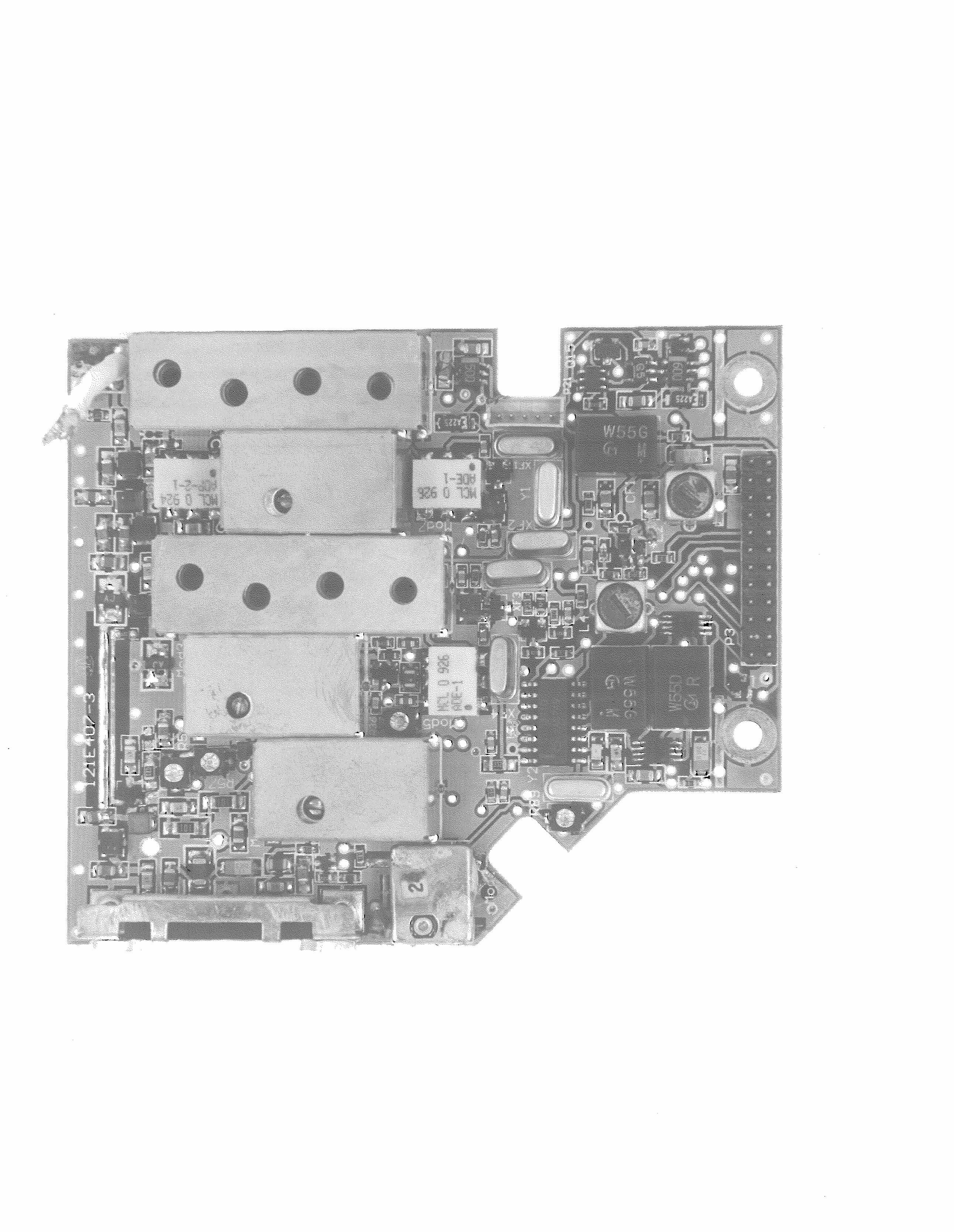
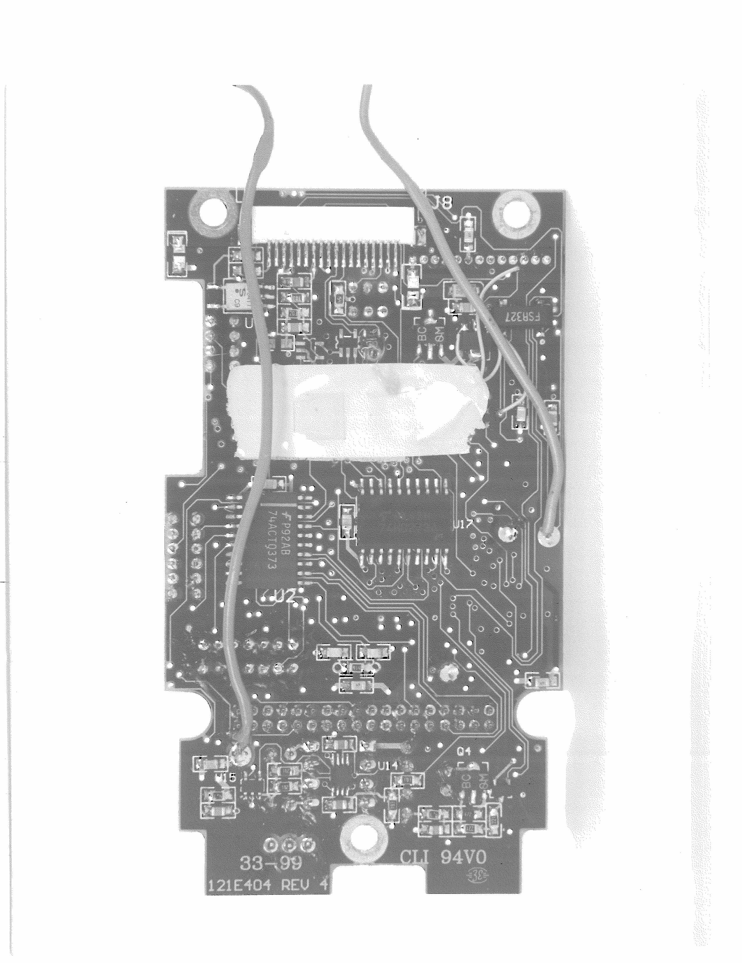
Document Text
Text extracted from the exhibit documents filed with the FCC. Open a document above to read the original.
Users Manual
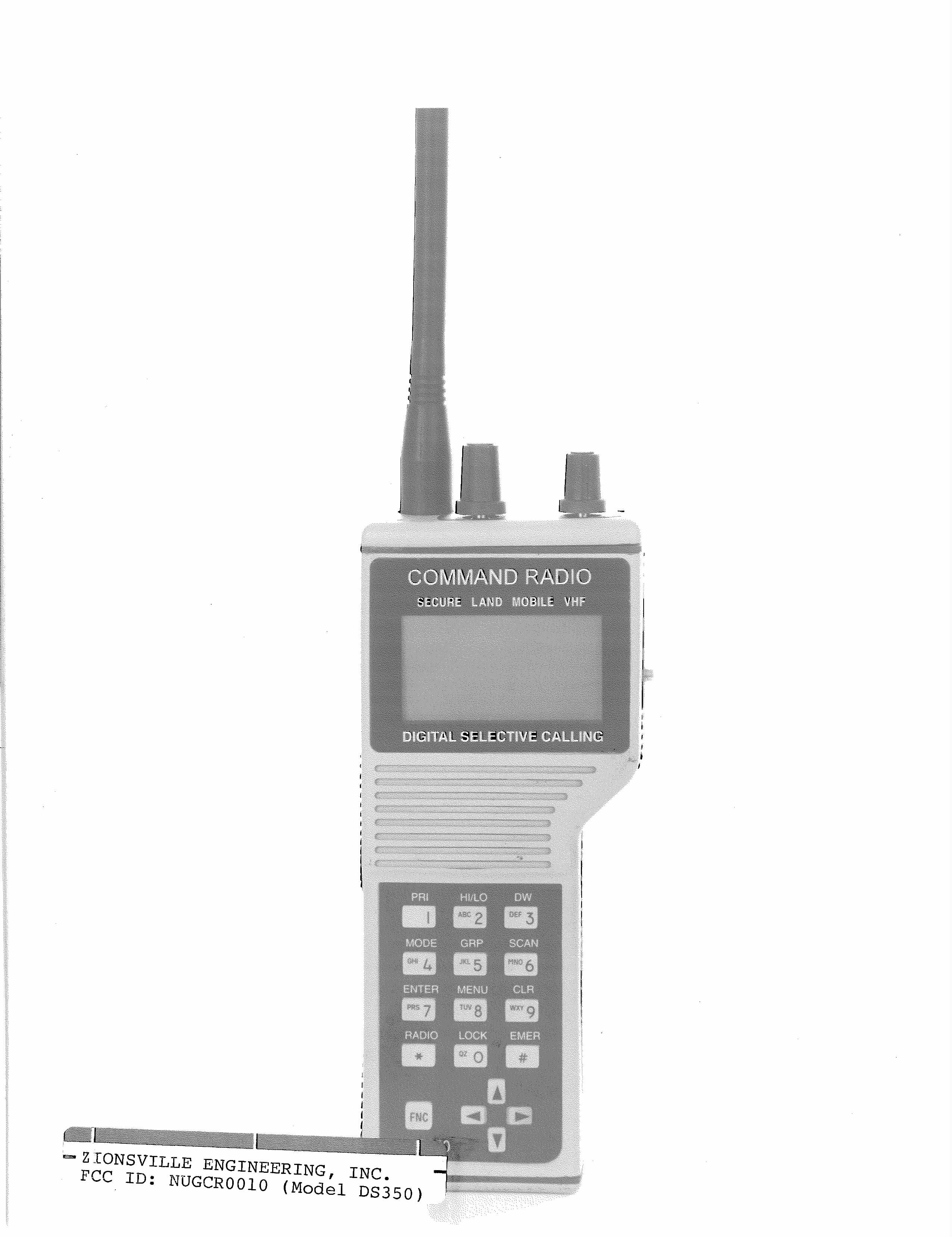
PRELIMINARY DS350 Command Radio Command RadioCommand Radio Command Radio Portable Marine Public Safety VHF/FM Transceiver with D igital S elective C alling and G lobal P ositioning S ystem Options Zionsville Engineering, Inc. 10706 De Andra Drive Zionsville, Indiana 46077 (317) 733-0513 FAX: (317) 733-0514 TABLE OF CONTENTS Introduction and Description ................................ 5 Command Radio DS350 Specifications ......... 6 Battery and Antenna Installation .......................... 7 Controls and Features ......................................... 8 LCD Panel Description ................................ 10 Operation ........................................................... 11 Basic Functions ........................................... 11 Placing a DSC Call ...................................... 12 Keypad Primary Functions .......................... 14 Keypad Secondary Functions ...................... 15 Navigating the Menu ................................... 16 Keypad Quick Reference ............................ 18 Battery Information ............................................ 19 Simplified Maintenance ...................................... 21 Battery Replacement ................................... 21 Battery Contact Cleaning ............................. 21 Simplified Troubleshooting ................................. 22 Troubleshooting Table ................................. 22 3 LIST OF FIGURES Figure 1. Command RadioCommand Radio Command RadioCommand Radio Command Radio DS350 ..............................5 Figure 2. Antenna Installation .....................................7 Figure 3. External Views ..............................................8 Figure 4. LCD Panel Location ...................................10 Figure 5. LCD Panel Display .....................................10 Figure 6. Keypad Layout ...........................................14 LIST OF TABLES Table 1. Command RadioCommand Radio Command RadioCommand Radio Command Radio DS350 Specifications .......6 Table 2. Keypad Quick Reference .............................18 Table 3. Troubleshooting ..........................................22 4 Figure 1. Command RadioCommand Radio Command RadioCommand Radio Command Radio DS350 INTRODUCTION AND DESCRIPTION The Command RadioCommand Radio Command RadioCommand Radio Command Radio DS350 is a 999-channel, state-of-the-art, microprocessor-controlled, synthesized portable FM transceiver employ- ing the following features: DSC - Digital Selective Calling GPS - Global Positioning System, internal NAV 12 DTMF - Dual Tone Multiple Frequency CTCSS - Continuous Tone Controlled Squelch System CDCSS – Continuous Digitally Controlled Squelch System WB/NB – Wide Band/Narrow Band The unit operates in the 150-174 MHz frequency range with power output selectable between 1W and 5W. The radio is housed in a ruggedized, shockproof, weather-resistant case and features a built-in lighted multifunction keypad (including DTMF). A large back-lit Liquid Crystal Display (LCD) provides important information such as channel numbers and names, Dual Watch/Channel 16, GPS information (i.e., position and time), onscreen DSC messaging, and other mode selection data. Additionally, the DS350 offers a secure voice scram- bler, NMEA Data I/O port (optional adapter for PC connection), Dual Watch and Programmable Scan functions, Emergency Distress, Group Calling, Call Waiting, and Telephone Interconnect capability. Power is provided by a high-energy Nickel Metal Hydride (NiMH) battery pack which can be rapidly recharged in 1-2 hours. Optionally, the radio can be powered by five (5) AA-cell alkaline batteries. Optional Accessories: Carrying Case (CC) Remote Speaker/Microphone (SM1) Drop-in Quick-Charge Base (BC1) 12V DC Power Cable (BA12) AA Battery Pack (BPA1) 5 Table 1. Command RadioCommand Radio Command RadioCommand Radio Command Radio DS350 Specifications COMMAND RADIO DS350 SPECIFICATIONS GENERAL: Temperature Range-30 o to +60 o C Frequency Stability+/- 2.5 PPM Frequency Response24 MHz (150 - 174 MHz ) Frequency Increments2500 Hz RECEIVER:WBNBGuard Sensitivity 12 dB SINAD0.35 μ V0.35 μ V0.35 μ V Selectivity (Adjacent channel)75 dB65 dB65 dB Spurious Response70 dB70 dB70 dB Intermodulation70 dB65 dB65 dB Audio Power0.5 W0.5 W0.5 W Audio Distortion @ rated P 0 5 %5 %5 % FM Hum and Noise40 dB34 dB34 dB Conducted Emissions-57 dBm-57 dBm-57 dBm TRANSMITTER: Carrier Power Output5W – 1 dB 5W – 1 dB 1W – 2 dB 1W – 2 dB Spurious Emissions-60 dBc-60 dBc Audio Distortion5 %5 % Audio Modulation+/- 5 kHz +/- 2.5 kHz FM Hum and Noise40 dB34 dB 6 Figure 2. Antenna Installation BATTERY AND ANTENNA INSTALLATION Battery Pack (BP1) The unit is shipped with the BP1 Battery Pack pre-installed inside the radio case. The BP1 is uncharged upon arrival. It is designed to be recharged inside the radio case. The NiMH batteries are capable, under normal operation and environment conditions, of 500 charge/discharge cycles. Battery pack charging and recharging are covered in the Battery Information section of this manual, page19. Battery pack replacement is covered in the Simplified Maintenance section of this manual, page 21. Antenna The antenna is a flexible, helical-wound type and is matched, by model number, to the operating frequency range of the unit. The antenna con- nector is a standard TNC type. To install the antenna, carefully align the antenna connector to the unit connector and push while turning the antenna clockwise until tight. To remove the antenna, reverse the proce- dure. 7 8 9 6 10 7 TOP VIEW 6 5 7 1 15 4 11 13 3 2 12 LEFT SIDE FRONT VIEW RIGHT SIDE 16 14 BOTTOM VIEW Figure 3. External Views 8 CONTROLS AND FEATURES All numbers below (1 through 15) refer to Figure 3 on page 8. 1. The LCD Panel – See Figure 5 on page 10. 2. Function Key – Used to select secondary functions for number keys on the Keypad. 3. Keypad – Used to select primary functions with a single keypress as shown in Table 2 on page 16. The two except…
Text truncated - open the document above for the full version.
Users Manual
FCCMarineFreq.doc1 of 304/11/01 Table 1 USA VHF MARINE CHANNEL ASSIGNMENTS ChannelChannelReceiveTransmit NumberAssignmentFrequencyFrequency MHz MHz 01PORT OPERATIONS156.050156.050 03INTERSHIP & COAST STATION156.150156.150 * 05PORT OPERATIONS156.250156.250 (Intership/Ship-Coast) 06SHIP TO SHIP SAFETY ONLY156.300156.300 07COMMERCIAL 156.350156.350 (Intership/Ship-Coast) 08COMMERCIAL (Intership)156.400156.400 09COMMERCIAL & NON COMMERCIAL156.450156.450 (Intership/Ship-Coast) 10COMMERCIAL156.500156.500 (Intership/Ship-Coast) 11COMMERCIAL156.550156.550 (Intership/Ship-Coast) 12PORT OPERATIONS156.600156.600 (Intership/Ship-Coast) 13NAVIGATION (Ship to Ship)156.650156.650 14PORT OPERATIONS156.700156.700 (Intership/Ship-Coast) 15ENVIRONMENTAL 156.750 16 DISTRESS, SAFETY, AND 156.800156.800 CALLING (Intership/Ship-Coast) 17STATE CONTROL 156.850156.850 18COMMERCIAL156.900156.900 (Intership/Ship-Coast) 19COMMERCIAL156.950156.950 (Intership/Ship-Coast) 20PORT OPERATIONS157.000157.000 (Intership/Ship-Coast) 21U.S. GOVERNMENT ONLY157.050157.050 * 22COAST GUARD LIAISON157.100157.100 23U.S. GOVERNMENT ONLY157.150157.150 * 24PUBLIC CORRESPONDENCE161.800157.200 (Ship-Coast) 25PUBLIC CORRESPONDENCE161.850157.250 (Ship-Coast) 26PUBLIC CORRESPONDENCE161.900157.300 (Ship-Coast) 27PUBLIC CORRESPONDENCE161.950157.350 (Ship-Coast) 28PUBLIC CORRESPONDENCE162.000157.400 (Ship-Coast) 61160.675156.075 * 63PORT OPERATIONS156.175156.175 64160.825156.225 * 65PORT OPERATIONS156.275156.275 (Intership and Ship-Coast) 66PORT OPERATIONS156.325156.325 (Intership and Ship-Coast) 67COMMERCIAL MISS. RIVER 156.375156.375 68NON-COMMERCIAL156.425156.425 FCCMarineFreq.doc2 of 304/11/01 69NON-COMMERCIAL156.475156.475 70DIGITAL SELECTIVE CALLING156.525156.525 ** (do not use as working channel) 71NON-COMMERCIAL156.575156.575 72NON-COMMERCIAL156.625156.625 73PORT OPERATIONS156.675156.675 (Intership/Ship-Coast) 74PORT OPERATIONS156.725156.725 (Intership/Ship-Coast) 77PORT OPERATIONS (Intership)156.875156.875 78NON-COMMERCIAL156.925156.925 79COMMERCIAL156.975156.975 (Intership/Ship-Coast) 80COMMERCIAL157.025157.025 (Intership/Ship-Coast) 81U.S. GOVERNMENT ONLY157.075157.075 * 82U.S. GOVERNMENT ONLY157.125157.125 * 83U.S. GOVERNMENT ONLY157.175157.175 * 84PUBLIC CORRESPONDENCE161.825157.225 (Ship-Coast) 85PUBLIC CORRESPONDENCE161.875157.275 (Ship-Coast) 86PUBLIC CORRESPONDENCE161.925157.325 (Ship-Coast) 87PUBLIC CORRESPONDENCE161.975157.375 (Ship-Coast) 88COMMERCIAL (Intership)157.425157.425 * Not for use by the general public. ** Transmitter disabled except for DSC calling. Table 2 INTERNAT IONAL VHF M ARINE CHANNEL ASSIGNMENTS ChannelChannelReceiveTransmit NumberAssignmentFrequencyFrequency MHz MHz 01PORT OPERATIONS160.650156.050 02PORT OPERATIONS-160.700156.100 03PUBLIC CORRESPONDENCE160.750156.150 04PORT OPERATIONS160.800156.200 05PORT OPERATIONS160.850156.250 06INTERSHIP SAFETY156.300156.300 07PUBLIC CORRESPONDENCE160.950156.350 08COMMERCIAL156.400156.400 09PORT OPERATIONS156.450156.450 10PORT OPERATIONS156.500156.500 11PORT OPERATIONS156.550156.550 12PORT OPERATIONS156.600156.600 13PORT OPERATIONS156.650156.650 14PORT OPERATIONS156.700156.700 15ON-BOARD COMMUNICATIONS156.750156.750 16 DISTRESS SAFETY & CALLI NG156.800156.800 17ON-BOARD COMMUNICATIONS156.850156.850 18PORT OPERATIONS161.500156.900 19PORT OPERATIONS161.550156.950 20PORT OPERATIONS161.600157.000 FCCMarineFreq.doc3 of 304/11/01 21PORT OPERATIONS161.650157.050 22PORT OPERATIONS161.700157.100 23PUBLIC CORRESPONDENCE161.750157.150 24PUBLIC CORRESPONDENCE161.800157.200 25PUBLIC CORRESPONDENCE161.850157.250 26PUBLIC CORRESPONDENCE161.900157.300 27PUBLIC CORRESPONDENCE161.950157.350 28PUBLIC CORRESPONDENCE162.000157.400 60PORT OPERATIONS160.625156.025 61PORT OPERATIONS160.675156.075 62PUBLIC CORRESPONDENCE160.725156.125 63PORT OPERATIONS160.775156.175 64-160.825156.225 65SPECIAL EMERGENCY160.875156.275 66-160.925156.325 67PORT OPERATIONS156.375156.375 68PORT OPERATIONS156.425156.425 69PORT OPERATIONS156.475156.475 70DIGITAL SELECTIVE CALLING156.525156.525 ** (do not use as working channel) 71PORT OPERATIONS156.575156.575 72COMMERCIAL156.625156.625 73PORT OPERATIONS156.675156.675 74PORT OPERATIONS156.725156.725 75-156.775156.775 76-156.825156.825 77COMMERCIAL156.875156.875 78PORT OPERATIONS161.525156.925 79PORT OPERATIONS161.575156.975 80PORT OPERATIONS161.625157.025 81PORT OPERATIONS 161.675157.075 82PORT OPERATIONS161.725157.125 83PUBLIC CORRESPONDENCE161.775157.175 84PUBLIC CORRESPONDENCE161.825157.225 85PUBLIC CORRESPONDENCE161.875157.275 86PUBLIC CORRESPONDENCE161.925157.325 87PUBLIC CORRESPONDENCE157.375157.375 88PUBLIC CORRESPONDENCE157.425157.425 ** Transmitter disabled except for DSC calling. Table 3 VHF MARINE WEATHER CHANNEL ASSIGNMENTS ChannelChannelReceive NumberAssignmentFrequency MHz WX0-163.275 WX1NOAA WEATHER162.550 WX2NOAA WEATHER162.400 WX3NOAA WEATHER162.475 WX4NOAA WEATHER162.425 WX5NOAA WEATHER162.450 WX6-162.500 WX7-162.525 WX8CANADIAN WEATHER161.650 WX9-161.775
Attestation Statements
Response to FCC questions of Feb. 15, 2000 Explanation of radio use: The intent of this transceiver is to provide a much- needed radio for use along coastlines. When working coastlines or in harbors, a marine radio is required to communicate with boats, Coast Guard, etc. In some cases, it can also become very important to communicate with land based public safety officials for coordinated efforts. The DS350 can be very useful in this area. It allows the user the ability to communicate using the normal PLMR frequencies and at the same time communicate with other governmental agencies using the marine channels. The intended use of this radio is for public safety and/or government agencies. 1. The DS350 can be set up in two different ways for RF power control: a. If the DS350 is programmed as a marine radio, the power control setting is adjusted for 1 Watt in the low power mode. When used in conjunction with Private Land Mobile Radio (Part 90)(PLMR) frequencies, that setting is 1 Watt. A qualified technician at a radio dealer’s location does this setting. b. If the DS350 is programmed to be used only as a PLMR radio, the dealer’s technician could adjust the power control setting for either 1 Watt or 2 Watts in the low power mode. 2. The DS350 is programmed to use the marine channels in Part 80 as defined in Parts 80.373(f) and 80.871. Power output on each channel can be reduced to 1 Watt via the HI/LO button. This radio is capable of being used as a ship station or a coastal station. 3. The DS350 can be set up in two different receiver and transmitter bandwidth modes: a. If the DS350 is programmed as a marine radio, the setting of the receiver IF filter bandwidth is always set for wideband operation (+/- 5 kHz deviation or 25 kHz channel separation). The transmitter deviation is set for +/- 5 kHz maximum. b. When the DS350 is programmed to be also used as a PLMR radio, the receiver IF filter bandwidth is programmed according to the Radio Frequency license issued by the FCC. The transmitter deviation is programmed on a per channel basis, either +/- 5 kHz or +/- 2.5 kHz. Therefore in the same unit, some PLMR channels may be wideband and others narrowband. NOTE: a qualified technician at a radio dealer’s location who has the software to accomplish this does this programming. This software is only sold to qualifying dealers and NOT to the general public per FCC rules. 4. Per the above explanation, the DS350 can be used effectively and legally in Part 22, 74, 80 and/or 90. We still respectfully request to have Type Acceptance issued as such.
ID Label/Location Info
R .167 Serial No. 350-XXXXXX Canada: Zionsville Engineering, Inc. Made Is U.S.A. Model No. DS350 VHF Transceiver FCC ID: NUGCR0010 NOTES: (UNLESS OTHERWISE SPECIFIED) 1. BLACK LETTERING ON SILVER BACKGROUND FCC LABEL 1 OF 1 1 = 1 J. WRIGLEY09/24/99 A121-1161 1.250" 1.480"
Operational Description
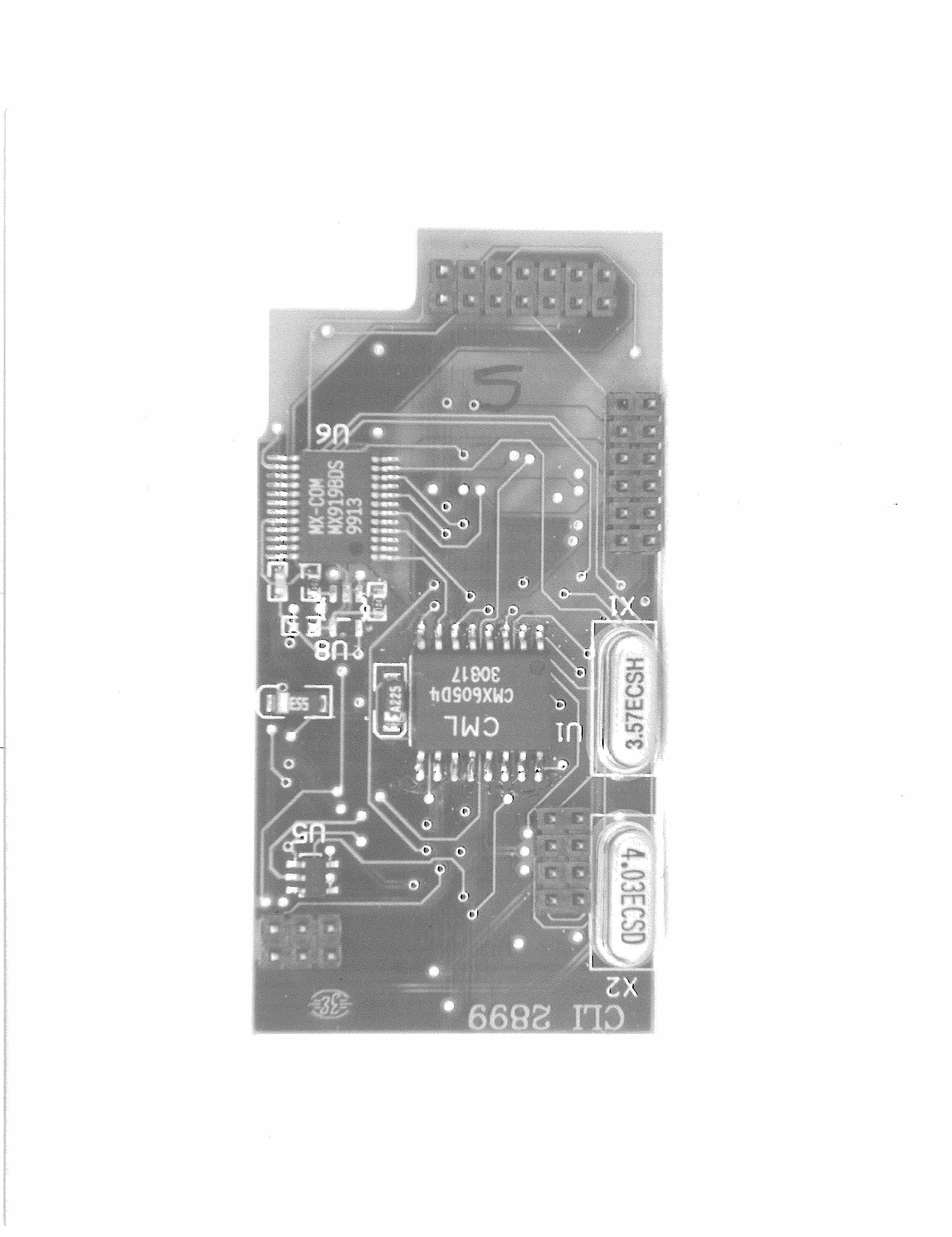
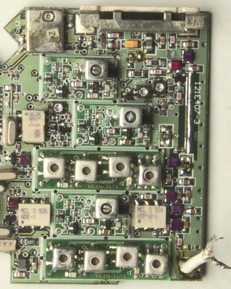
Description of all circuitry and devices for determining and stabilizing frequency: This transceiver uses three VCOs (Mod1, Tx; Mod3, Primary Rx; Mod6, DSC Rx) and two PLL (U5 and U6) circuits to generate the necessary frequencies for receiver LOs and transmitter frequency generation. The reference standard for the synthesized frequencies is Mod2. Mod2 is a TCXO with +/- 2.5 PPM frequency accuracy over the temperature range of -30°C to +60°C. The Mod2 signal is divided down internally in the PLL ICs to 20000 (U5) or 2500 (U6) Hz. U5 has a fractional N divider with a Modulo of 8; therefore, the final frequency increment available is 2500 Hz. U6 is a typical PLL synthesizer IC with the dual modulus pre-scaler internally. Both PLL ICs have a phase comparator that generates an error voltage which control the VCO’s frequencies and moves the VCO frequencies in a direction that maintains the desired accuracy based on the Mod2 frequency stability characteristics. Description of all circuits/devices used for suppression of radiation: Transmitter harmonic suppression is achieved through the transmitter low pass filter sections. C57, L9 and C58 form a single section π filter for initial filtering of the transmitter harmonics before the directional coupler. This type of section provides for good filtering at the higher harmonics (ultimate rejection). Once the transmit signal goes through the directional coupler and T/R switch (D5), it enters another low pass filter. L12, C64, C65, L13, C67, L14 and C66 form this filter. This filter provides additional filtering especially for the second and third harmonics. It also has some higher harmonic filtering. Description of all circuits/devices used for limiting modulation: Microphone audio is pre-emphasis and amplified by U5 (internal microphone) or U19 (external microphone). The output of either one of these amplifiers is then combined with different signalling signals and amplified in U3 where it is also limited. U3 is a complex audio processing IC which also provides the low pass filter to insure good emissions mask response. The audio output signal from U3 is adjusted for +/- 5 kHz deviation by R36. For +/- 2.5 kHz deviation channels, a 6 dB attenuator in U3 is electronically added to the signal path to reduce the signal for +/- 2.5 kHz deviation. Description of all circuits/devices used for limiting power: The transmitter RF power output is fed through a directional coupler. A small amount of RF power is then rectified by D4 and filtered by C60. This resultant DC level is then used to control the bias on Q10. Q10 conducts and the resultant voltage drop across R52 reduces the voltage seen at Mod4-Vgg. Vgg’s maximum voltage is limited to 4.0 volts. In the 5 watt mode, Q12 is turned ON (R57 shorted). As the RF power output rises above 5 watts, the rectified DC voltage rises which reduces the voltage at Vgg; thereby, lowering the RF output. In the 1/2 watt mode, Q12 is turned OFF. This puts R57 into the circuit and raises the effective voltage seen by the base of Q10. Q10 conducts more, thereby lowering the voltage at Mod4-Vgg. Conversely, if the RF power is sagging the above described feedback loop tries to compensate Mod4-Vgg to supply the desired output power.
Operational Description
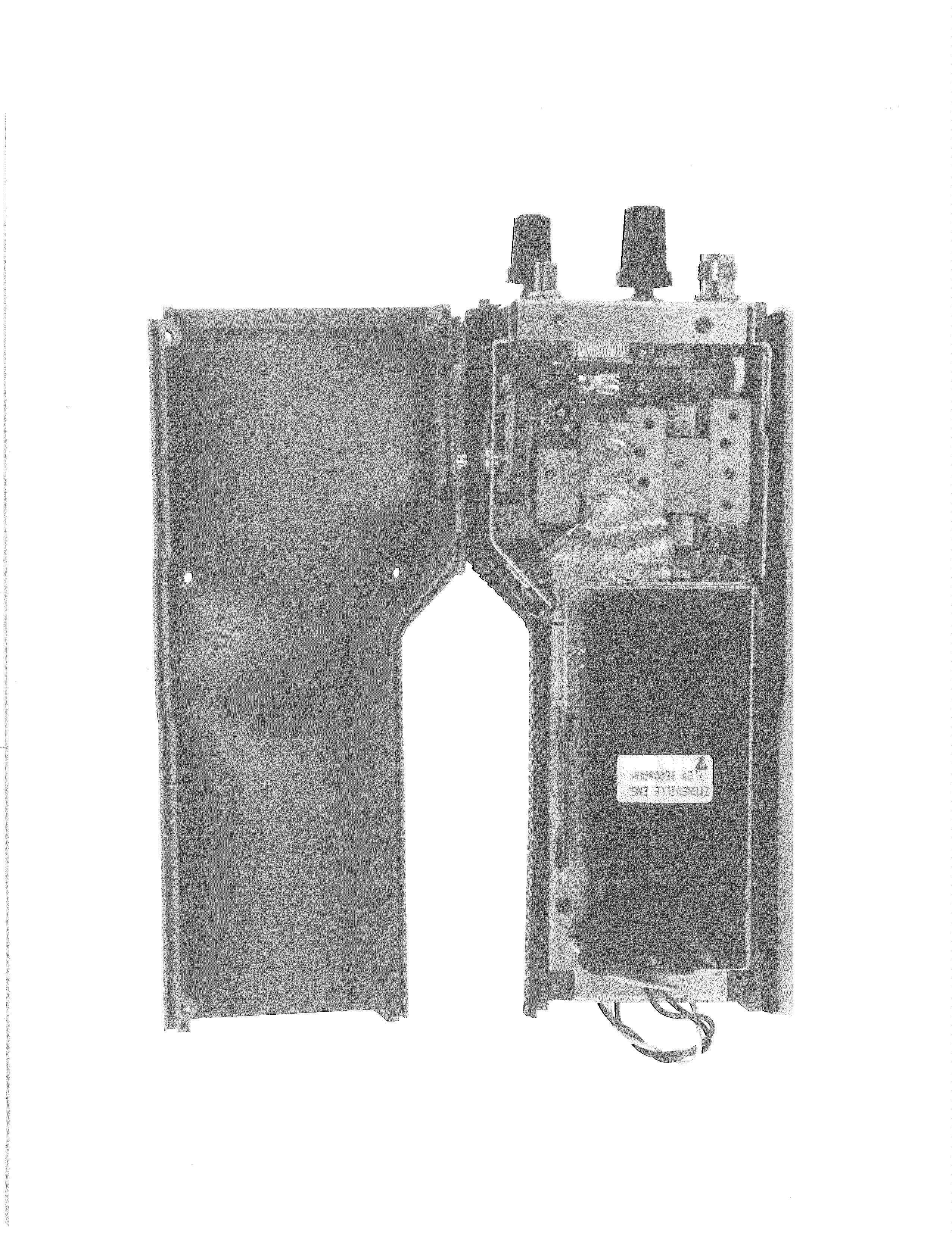
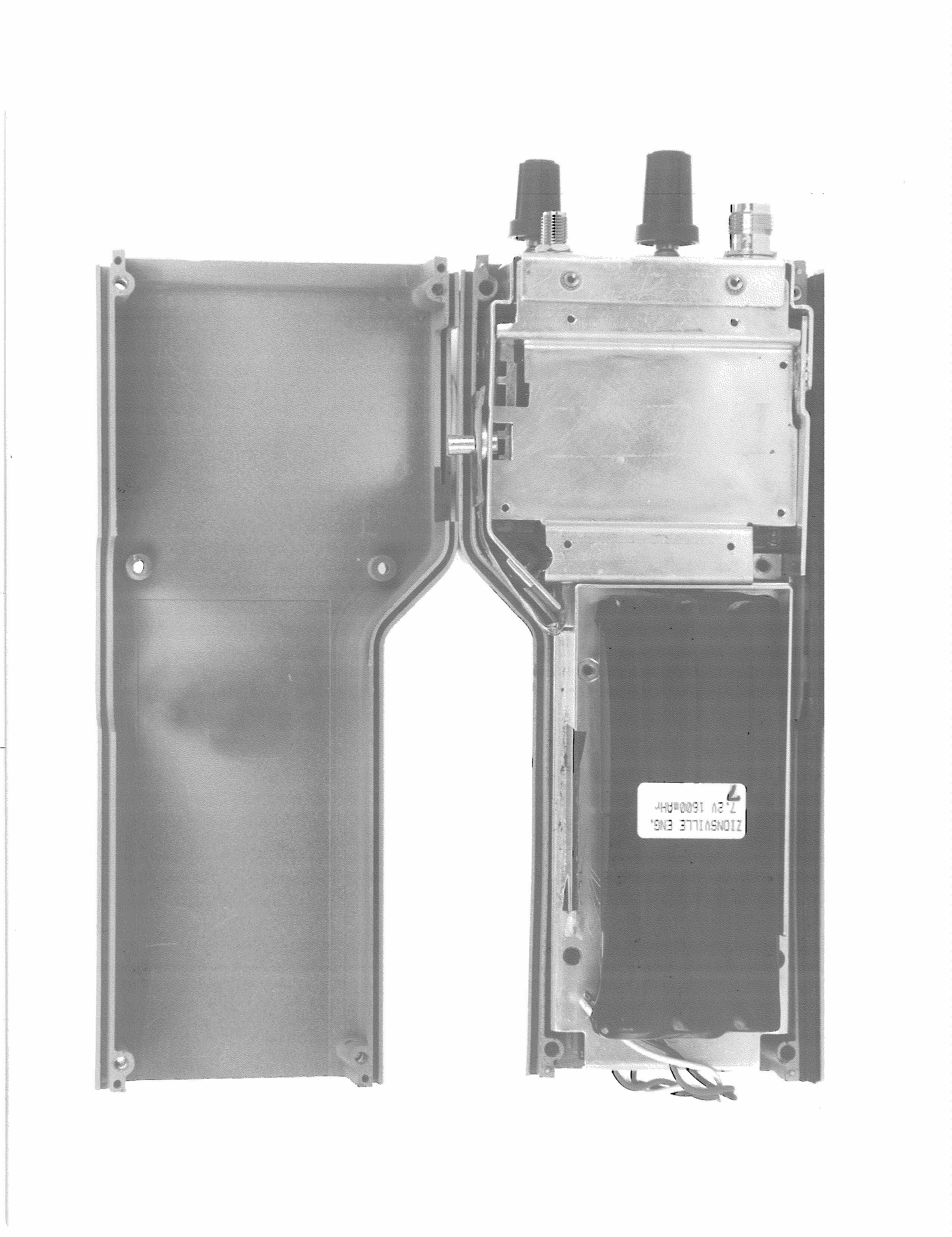
DS 350 COMMAND RADIO VHF HANDHELD TRANSCEIVER The DS350 transceiver consists of four major sections 1. Main RF board 2. Main Logic board 3. Audio Processing Module 4. Keyboard PCB MAIN RF BOARD The main RF board contains one complete synthesized VHF transmitter and two synthesized VHF receivers. One receiver is used as a guard or overhead channel. It is used to receive channeling or data commands. The other receiver is used for voice (working channel). The transmitter can send voice or data on any frequency allowed by its programming. Transmitter The transmitter shares the synthesizer IC (U5) with the working channel receiver. This transmitter has its own VCO (MOD1, TX VCO). Power is switched on to the transmitter via transistors Q15, Q16 and Q17. TX 5.5V is the transmitters power supply. The TX VCO can be frequency-modulated by applying an AC signal (modulation) at its MOD pin. Another modulation signal is applied to the reference oscillator (MOD2, TCXO). MOD2 is a temperature controlled/voltage controlled crystal oscillator. It is the main reference for both synthesizers. It maintains a +/- 2.5-PPM frequency accuracy from –30°C to +60°C. Modulating this reference aids in producing more linear FM modulation at low modulating frequencies. The FM signal from the TX VCO is buffered and amplified by transistors Q6 and Q8. This signal drives the Transmit Power Amplifier (MOD4, TX PA) via coupling capacitor C52. Buffer/amplifier Q6 also provides the RF signal feedback to the synthesizer IC (U5). Diode D2 is switched on by the TX 5.5V supply to allow the signal to be coupled to U5. Diode D3 isolates this signal from the receive VCO buffer. The TX PA module amplifies the signal to eventually drive the antenna. The output of the TX PA is passed through a low pass filter C57, C58 and L9. This signal is then fed to a directional coupler in order to measure the power being “sent” to the antenna. The directional coupler DC1 and DC2 are actually PC board traces (a coupling strip). Power going to the antenna is coupled to the strip DC2 and rectified by diode D4 and filtered by C60. As the forward power increases, the voltage drive to Q10 increases. As Q10 conducts harder due to the increased drive, Q9 will have less available base voltage. Since Q9 is an emitter follower, the reduced base voltage causes the emitter to drop in voltage as well. This emitter is the control voltage (Vgg) that controls the transmit PA module. As Vgg drops, the power output drops. This forms a feedback loop to stabilize the forward power to the antenna. Adjustment R56 controls the transmitter in the HI (5W) power mode. Q12 is on, shorting R57 in the HI power mode. In the low power mode, Q12 is off, putting R57 into the circuit; this adjusts the transmitter power in the LO (1 or 2W) power mode. A second control, PA EN (PA Enable) controls Q18. Q18 is a dual transistor used to allow Q9 to have a collector supply. If the PA EN pin (P3-13) does not switch HI, Q9 cannot supply Vgg (control voltage) to the TX PA. If the transmit PLL is out-of-lock, transmit power is switched off by this control path. In the transmit mode, the TX 5.5V supply turns on diode D5 via R60, R39, L10, L11 and D6. D5 allows the forward transmit power to be sent to the low-pass filters of L12, C64, C63, C65, L13, L14, C67, and C66. This filters out the upper harmonics that are produced by the transmit power amplifier. The forward current that switches on D5 also switches on D6. This prevents damaging transmit power from reaching the power splitter and RF amplifier in the receiver section. In the receive mode, D5 and D6 are off, allowing received antenna current to flow to the receiver section. D5 prevents the current from traveling backwards into the transmitter power sections. Working channel receiver Voltage regulator U8 provides 5.5V to Q15. This receiver has it’s power switched on by Q15 (RX 5.5V). RX 5.5V supplies power to the receive VCO (MOD3). It also supplies power to the Guard Channel Receiver. The VCO signal is buffered and amplified by Q7. Diode D3 is switched on by the RX 5.5V supply. This VCO signal is fed through the same filters as the transmit VCO signal. The synthesizer IC (U5) uses this signal as a feedback signal. U5 is a fractional N synthesizer that divides the reference signal produced by MOD2. The result is an available frequency increment of 2500Hz. This reference is compared with the feedback signal from the VCO modules (MOD1 in transmit, MOD3 in receive) by the phase detector in U5. If the VCO signal is lower than it should be, U5 provides pulses to raise it. If the VCO signal is higher than it should be, U5 provides pulses to lower it. A low-pass filter made from C90, R80, C89, R79, and C88 filter these pulses into a DC voltage used by the VCO (transmit and receive) to control its frequency. This DC voltage (tuning voltage) is also used by the front end module (MOD8) to center its frequency response, thereby tracking the desired receive frequency. The receive VCO signal (after buffering/amplification by Q7) is fed to the first mixer (MOD5). MOD5 is a passive, double balanced mixer module. The other input to the mixer is the RF signal coming from MOD8. The signal from the antenna passes through the transmitters low-pass filters and is blocked by diode D5. D6 is also off in the receive mode allowing the received signal to pass through a high-pass filter of L23, C70, C69, L15, C71, L25, L24, and C73. This signal is then fed to an RF amplifier (Q13) that amplifies and divides the signal available from the antenna. The RF signal at the antenna must be split evenly between two receivers. Q13 uses a power splitter transformer (PS1) to differentially drive the two front- end modules (MOD8 and MOD9). MOD8 is a track - tuned filter and RF amplifier. The output of MOD8 drives the RF input of the first mixer (MOD5). The desired IF output of MOD5 is 21.4MHz. This first IF signal from the mixer is applied to transistor Q3. This stage effectiv…
Text truncated - open the document above for the full version.
Parts List/Tune Up Info
Command Radio Tuning Procedure. TRANSMITTER TUNING Preliminary 1. Set R56 to maximum CCW. 2. Connect 50 Ohm RF Load (10 Watt minimum rating) to J25 (Antenna). See Figure 1. 3. Connect frequency counter and a FM modulation analyzer to RF Load output. 4. All adjustments are made with the transmitter PTT depressed. Frequency Adjust. 1. Set Transmitter to a frequency near 161.0000 MHz in high power mode. 2. Push PTT and temporarily adjust R56 for a RF power level of 3 watts. 3. Adjust Trimmer Capacitor on the TCXO module (Mod 2) for a frequency of 161.00000 MHz ± 50 Hz. VCO Adjust 1. Set Transmitter to a frequency near 173.9500 MHz. 2. Adjust L1 on Transmitter VCO Board (Mod 1) for a DC voltage of 10 Volts at the junction U12-1 and R116. 3. Set Transmitter to a frequency near 150.0500 MHz. 4. Check that the DC voltage on Vt at the junction U12-1 and R116 is between 2.75 and 3.25 Volts. Master Deviation Adjust 1. Preset R36 (Master Deviation) and R89 (Balance) on RF Board to mid- range. 2. Set unit to non-tone/data channel near the middle of the frequency range. 3. Connect dummy microphone circuit to P5 (External Speaker and Microphone Plug). Connect an Audio generator to the dummy microphone circuit. See Figure 1. 4. Connect an oscilloscope to the FM Modulation Analyzer. Set audio generator to 1000 Hz and increase audio output level until the sine wave on the oscilloscope just shows clipping. Increase the audio output level by 20 dB (10 times). 5. Adjust R36 (Master Deviation) trimmer for ±4.2 kHz deviation. Change the frequency of the audio generator to 300 Hz and adjust R89 (Balance) for ±4.2 kHz deviation. Observe the demodulated waveform on the oscilloscope. The correct waveform is shown below: a. Correctb. Incorrectc. Incorrect 6. Repeat step 5 several times checking deviation and the demodulated waveform since R36 (Master Deviation) and R89 (Balance) interact. CTCSS/DCS Adjust 1. Remove the 300 or 1000 Hz tone from dummy microphone circuit. 2. Set the unit to a frequency programmed for a CTCSS tone. 3. Adjust R14 (Tone Deviation) for ± 700 Hz deviation. 4. Set unit to a frequency programmed with a DCS tone. Check that deviation is with in 50 Hz of ±700 Hz. DTMF Adjust 1. Set unit to a channel with the DTMF option. 2. Hold down pushbutton numbered 5 and set R15 (DTMF Adjust) for ± 3.5 kHz deviation. DSC Adjust 1. Set unit to test channel (X) that provides continuous DSC coding. 2. Adjust R16 (DSC Adjust) for ±3.5 kHz deviation. 4FSK Adjust 1. Set unit to non-tone/data channel. 2. Connect 4FSK Data Generator with RS232 interconnect to the Options Connector. See Figure 1. Note: This disconnects the audio generator from the dummy microphone circuit. 3. Adjust R17 (4FSK Adjust) for ±3.5 kHz deviation. RF Power Adjust Note: Continuous transmission will cause the PA Module (Mod4) to heat up. These adjustments should be made with PA Module near ambient temperature. 1. Set unit to channel near the middle of the frequency range that is programmed for high power. 2. Adjust R56 (Hi Power) for 5 watts maximum. 3. Set unit to channel near the middle of the frequency range that is programmed for low power. 4. Adjust R57 (Lo Power) for 1 watts typical. RECEIVER TUNING Main Receiver Section VCO Adjust 1. Set Main Receiver to a frequency near 173.9500 MHz. 2. Adjust L1 on Main Receiver VCO Board (Mod 3) for a DC voltage of 10 Volts at the junction U12-1 and R116. 3. Set Main Receiver to a frequency near 150.0500 MHz. 4. Check that the DC voltage at the junction U12-1 and R116 is between 2.75 and 3.25 Volts. Front End Alignment. 1. Set Main receiver to a frequency near 161.0000 MHz. 2. With FM signal generator set to the receive frequency, adjust output level for 0.1 Vpp (455 kHz) at via going to Pin 5 of U2. 3. Adjust L1, L2 L3 and L4 (in that order) on the main receiver Front End board (FE) (Mod 8) for maximum signal on the oscilloscope. Reduce RF signal generator output level as necessary to keep near 0.1 Vpp on oscilloscope. Repeat. IF Alignment 1. Using same frequency, set RF level to 100 μV and modulate RF generator with 1000 Hz tone deviated at 1.5 kHz. 2. Connect AC Voltmeter to external speaker. Use 3 Volt scale. 3. Unsquelch radio (maximum CCW position) and adjust volume control for mid range reading on the AC Voltmeter. 4. Adjust L2 on the RF board for maximum 1000 Hz level on the AC Voltmeter. Readjust volume control if necessary. 5. DC voltage on pin 19 of P3 should be 2.1 volts. Slight adjustment of L2 may be necessary. 6. Check 12 dB SINAD on this channel and the two channels used for VCO adjust. RF level for 12 dB SINAD should be less than 0.35 μV. Guard Receiver Section VCO Adjust 1. Set Guard Receiver to a frequency near 173.9500 MHz. 2. Adjust L1 on Guard VCO Board (Mod 6) for a DC voltage of 10 Volts at the junction U13-1 andR14. 3. Set Guard Receiver to a frequency near 150.0500 MHz. 4. Check that the DC voltage at the junction of U13-1 and R14 is between 2.75 and 3.25 Volts. Front End Alignment. 1. Set Guard receiver to a frequency near 161.0000 MHz. 2. With FM signal generator set to the receive frequency, adjust output level for 0.1 Vpp (455 kHz) at via going to Pin 5 of U1. 3. Adjust L1, L2 L3 and L4 (in that order) on the guard receiver FE board (Mod 9) for maximum signal on the oscilloscope. Reduce RF signal generator output level as necessary to keep near 0.1 Vpp on oscilloscope. Repeat. IF Alignment 1. Using same frequency, set RF level to 100 μV and modulate RF generator with 1000 Hz tone deviated at 1.5 kHz. 2. Temporarily connect 18K resistor in series with 47000 pF capacitor to ground to pin 19 of P3. Connect an Oscilloscope to the junction of the resistor and capacitor. Use 0.1 volt/div scale. 3. Adjust L2 on the RF board for maximum 1000 Hz signal on the oscilloscope. 4. DC voltage on pin 20 of P3 should be 2.1 volts. Slight adjustment of L2 may be necessary. 5. Check 12 dB SINAD on this channel and the two channels used for VCO adjust. RF level for 12 dB SINAD should b…
Text truncated - open the document above for the full version.
Schematics
1234 A B C D 4321 D C B A ScaleSheet SizeFCSM No.DWG No.Rev 1 of 1 A121e203B Zionsville Engineering, Inc. 10706 De Andra Drive Zionsville, IN 46077 COMMAND RADIO - Top Panel Connections D1 H101CSRD D2 H101CGD R1 300 R2 300 RSW1 XVB93 RSW2 XVB93 8/12/99, rad 12345678910 J1 52271-1090 B+SWB+SVOICEVOLUMETONEWRSSISQUELCHREDGREEN R3Rx ON-OFF / VOLUME TONE / SQUELCH RED GRN C1 .01uF C2 .01uF
Schematics
123456 A B C D 6 54321 D C B A ScaleSheet SizeFCSM No.DWG No.Rev 1 of 1 C121E2045 Zionsville Engineering, Inc. 10706 De Andra Drive Zionsville, IN 46077 COMMAND RADIO - CPU and Interface A19 1 A11 13 A18 2 A9 15 A17 3 A7 17 A16 4 A5 19 A15 5 A14 6 RESET 12 A13 7 A10 14 A12 8 A8 16 CE 9 A6 18 VCC 10 A4 20 NC 11 A2 22 A1 23 A0 24 DQ0 25 DQ1 26 DQ3 28 VSS 29 VSS 30 VCC 31 DQ4 32 DQ5 33 DQ6 34 DQ7 35 RY/BY 36 OE 37 WE 38 NC 39 NC 40 DQ2 27 A3 21 U3 AM29F080B GND GND VCC GND GND LVCC GND VCC GND X1 32.768KHz VCC B1 CR235…
Text truncated - open the document above for the full version.
Contact Information
Applicant
Paul J. Haeck(President)
317 733-0513Fax: 317 733-0514
Technical Contact
M. Flom Associates, Inc.Morton Flom
[email protected]480 926 3100
3356 N. San Marcos Place · Chandler, Arizona · United States
Non-Technical Contact
M. Flom Associates, Inc.Morton Flom
[email protected]480 926 3100
Test Firm
M. Flom Associates, Inc.Morton Flom
Technical Specifications
| # | Rule Parts | Frequency Range | Power Output | Emission | Tolerance |
|---|---|---|---|---|---|
| 6 | 22,74,80,90.21 | 150 MHz - 174 MHz | 1 W | 10K2F2B | 2.5 ppm |
Other Applications from Zionsville Engineering Inc
NUGZ800
Mar 15, 1998CXX - Communications Rcvr for use w/ licensed Tx and CBs
Equipment Class
CXX - Communications Rcvr for use w/ licensed Tx and CBs