NUKWLANGPCIIEEE 802.11g WIRELESS PCI ADAPTER
Unex Technology Corporation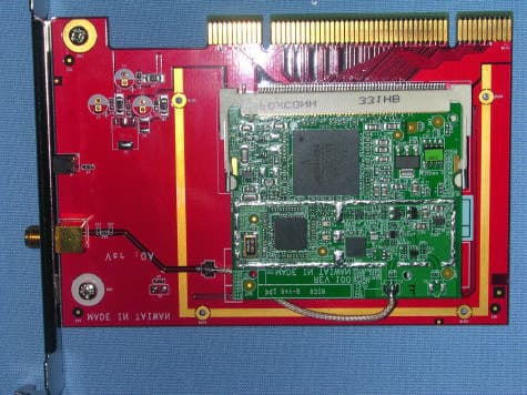
Click to zoom
Application Details
- Equipment Class
- DTS - Digital Transmission System
- Date of Grant
- Oct 21, 2003
- Application Purpose
- Original Equipment
- Date of Application
- Oct 21, 2003
- Equipment Note
- IEEE 802.11g WIRELESS PCI ADAPTER
- Frequency Range
- 2412.00000000 - 2462.00000000
- Company
- Unex Technology Corporation
- Country
- Taiwan
Documents & Files
Document Text
Text extracted from the exhibit documents filed with the FCC. Open a document above to read the original.
Users Manual
PC54G, MS-6825 Wireless 11g PCI Card User’ s Guide FCC Caution 1.The device complies with Part 15 of the FCC rules. Operation is subject to the following two conditions: (1) This device may not cause harmful interference, and (2) This device must accept any interference received, including interfer- ence that may cause undesired operation. 2.FCC RF Radiation Exposure Statement: The equipment complies with FCC RF radiation exposure limits set forth for an uncontrolled environment. This equipment should be installed and operated with a minimum distance of 20 centimeters between the radiator and your body. 3.This Transmitter must not be co-located or operating in conjunction with any other antenna or transmitter. 4.Changes or modifications to this unit not expressly approved by the party responsible for compliance could void the user authority to operate the equipment. Copyright Notice The material in this document is the intellectual property of MICRO-STAR INTER- NATIONAL. We take every care in the preparation of this document, but no guarantee is given as to the correctness of its contents. Our products are under continual improvement and we reserve the right to make changes without notice. Trademarks All trademarks used in this manual are the sole property of their respective owners. Windows is a registered trademark of Microsoft Corporation. Revision History RevisionHistoryDate V 1.0First ReleaseJuly 2003 Important Safety Precautions Always read and follow these basic safety precautions carefully when handling any piece of electronic component. 1.Keep this User’ s Manual for future reference. 2.Keep this equipment away from humidity. 3.Lay this equipment on a reliable flat surface before setting it up. 4.The openings on the enclosure are for air convection hence protects the equipment from overheating. 5.All cautions and warnings on the equipment should be noted. 6.Never pour any liquid into the opening that could damage or cause electrical shock. 7.If any of the following situations arises, get the equipment checked by a service personnel: Liquid has penetrated into the equipment The equipment has been exposed to moisture The equipment has not work well or you can not get it work according to User’ s Manual The equipment has dropped and damaged If the equipment has obvious sign of breakage 8.DO NOT LEAVE THIS EQUIPMENT IN AN ENVIRONMENT UNCONDI- TIONED, STORAGE TEMPERATURE ABOVE 60 O C OR BELOW -20 O C, IT MAY DAMAGE THE EQUIPMENT. 1 PC54G (MS-6825) - Wireless 11g PCI Card PC54G (MS-6825) Wireless 11g PCI Card, compliant with IEEE802.11g, is a high-efficiency wireless adapter for wireless networking at home, in office or in public places. The data transmission rate can be up to 54 Mbps and auto-negotiated to 48, 36, 24, 18, 12, 9, 6 Mbps (IEEE802.11g), or 11, 5.5, 2, 1 Mbps (IEEE802.11b). With PC54G (MS-6825), you can roam between confer- ence room and office without being disconnected the LAN cables; in addition, sharing files and printers can be easy tasks. The PC54G (MS-6825) is available to Microsoft Windows operating systems (Windows ® XP/2000/ME/98SE) and can be integrated into networking with either Ad-hoc mode (computer-to-computer, without an Access Point) or Infrastructure mode (computer-to-access point, an Access Point is required). >>> 1.1 Introduction 2 How PC54G (MS-6825) works Ad-hoc Mode : An Ad-hoc network is a local area network, especially one with wireless or temporary plug-in con- nections. Therefore, some of the network devices are part of the network only for the duration of a communica- tions session. Users in the network can share files, print to a shared printer, and access the Internet with a shared Gateway or Access Point. In this kind of network, new devices can be quickly added; however, users can only communicate with other wireless LAN devices that are in this wireless LAN workgroup, and are within range. >>> 1.2 (MS-6825) 3 Infrastructure Mode : The difference between Infrastruc- ture network and Ad-hoc network is that the former one includes an Access Point. In network environment, the Access Point can manage the bandwidth to maximize bandwidth utilization. Moreover, the Access Point enables users on a wireless LAN to access an existing wired network, allowing wireless users to take advantage of the wired networks resources, such as Internet, email, file transfer, and printer sharing. The scale and range of the Infrastructure networking are larger and wider than that of the Ad-hoc networking. (MS-6825) 4 Specifications>>> 1.3 General Operating systemMicrosoft ® Windows ® 98 SE/ ME/2000/XP Compliance- IEEE 802.11g/b - WECA WiFi - WHQL (Windows ME/2000/ XP) Operating Temperature0 ~ 55 O C Operating Humidity0 ~ 95%, non-condensing Physical Form Factor32-bit PCI v2.2 Dimensions (WxDxH)127.3 X 77.6 X 18.4 mm AntennaDipole Weight29 g Operation Voltage3.3 V Radio Frequency Range2.4GHz to 2.4835GHz Operating Channels 11 channels; maximum 3 non-overlapped channels; 25 MHz bandwidth/channel Data Rate andIEEE 802.11b(Auto-Fallback): Modulation Types- CCK @ 5.5 and 11 Mbps. - DQPSK @ 2Mbps. - DBPSK @ 1 Mbps. IEEE 802.11g(Auto-Fallback): - OFDM @ 54, 48, 38, 24, 18, 12, 9, 6 Mbps 5 Wireless MediumDirect Sequence Spread Spectrum (DSSS) with ACK; Half-Duplex Media Access ProtocolCarrier Sense Multiple Access with Collision Avoidance (CDMA/CA) Transmitter Output15dBm Power Performance RangeOpen Space: - 170 m @ 11 Mbps. - 50 m @ 54 Mbps. Indoor: - 120 m @ 11 Mbps. - 20 m @ 54 Mbps. Security Security Mechanism- 64-/128-bit WEP - AES-CCM Authentication Mode - WPA support - LEAP/PEAP support
Users Manual
6 System Requirements Before installing the PC54G (MS-6825), your PC should meet the following: - Desktop PC with standard PCI slot. - Windows ® 98SE/ME/2000/XP operating system. - Minimum 5MB free disk space for installing the driver and utilities. - CD-ROM drive, double speed or higher. >>> 1.4 >>> 1.5 Package Contents Unpack the package and check all the items carefully. If any item contained is damaged or missing, please contact your local dealer as soon as possible. Also, keep the box and packing materials in case you need to ship the unit in the future. The package should contain the following items: - One Wireless 11g PCI Card. - One external antenna. - One Quick Installation Guide. - One CD title including drivers, utilities, user’s manual and quick guide. 7 Product View>>> 1.6 Antenna Connector - connecting the external antenna. ACT LED - GREEN, indicating the networking status by: ON -The PC54G (MS-6825) is connected. Flash -The PC54G (MS-6825) is searching for available Access Point or receiving/ transmitting data over the wireless network. Golden Finger External Antenna
Users Manual
8 The following diagrams provide you a basic installation for your PC54G (MS-6825), which is suitable for most desktop PCs. For more information about the PCI slot, please refer to the user’s manual of your mainboard. Remove the computer cover. Locate the available PCI slot on your mainboard. Step 1. NOTE: Turn off your system and disconnect the power cable before installing the PC54G (MS-6825). PCI slot Put the PC54G (MS-6825) directly over the PCI slot and press it into the slot firmly. Step 2. Do not hold the PC54G (MS-6825) on the golden finger while installing; doing this may cause interference or damage. Hardware Installation 9 Replace the computer cover after securing the PC54G (MS-6825) with a bracket screw. Connect the external antenna to the connector on the PC54G’s (MS-6825) bracket. Step 3. Step 4. If your are not skilled at installing the PCI adapter, please ask the vendor or an experienced technician for help. Connecting the external antenna
Users Manual
10 This section describes the procedures of installing the driver and utility. Follow the instruction step by step to finish the installation. If you use Windows ® 98SE/ME, please prepare the Windows ® Setup CD at hand before installing the driver; because the system will ask you to insert the Setup CD to copy files during the installation. Installing on Windows ® 98SE/ME Insert the driver CD into your CD-ROM drive, and the Setup program should launch automatically. If the Autorun program doesn’t launch, click Start at the taskbar and select Run; type E:\setup.exe in the Open box and click OK, where E is your CD-drive. >>> 3.1 Windows 98SE The card should be installed into your computer before installing the driver and utility. Step 1. Click Software Installation 11 Click the Install Software button. Then, the system will detect a new device and start to configure the new device. Click Restart when prompted. After rebooting, the system will search the new device again, click Cancel to continue the installation from the InstallShield Wizard. The welcome screen of InstallShield Wizard appears. click Next. Read and accept the License Agreement, then click Next. Enter the user’s information (User Name, Organization) in the respective fields, then click Next. The installation screen of Setup program Click Step 2. 12 When the installation is completed, click Finish. The system will restart. Click Yes when prompted to reboot the system. After rebooting, the MSI Wireless LAN icon* appears in the status area. Step 4. Click Install and the program will copy the necessary files to the system. The progress indicator shows the in stalling status. Step 3. You may be asked to insert the Windows Setup CD during the installation. Please insert the Setup CD by the on-screen instruction to continue the installation. MSI Wireless LAN icon * The MSI Wireless LAN icon Not connected to the network. Connected to the network. Receiving/transmitting data from/to the network. 13 Installing on Windows ® 2000/XP Insert the driver CD into your CD-ROM drive, and the Setup program should launch automatically. If the Autorun program doesn’t launch, click Start at the taskbar and select Run; type E:\setup.exe in the Open box and click OK, where E is your CD-drive. >>> 3.2 Windows XP Click the Install Software button. Step 1. The card should be installed into your computer before installing the driver and utility. Click The installation screen of Setup program Click 14 Step 4. Step 3. The welcome screen of InstallShield Wizard appears. Click Next. Read and accept the License Agreement, then click Next. Enter the user’s information (User Name, Organization) in the respective fields, then click Next. Click Install and the program will copy the necessary files to the system. The progress indicator shows the in stalling status. When the installation is completed, click Finish. The MSI Wireless LAN icon* appears in the status area. Step 2. MSI Wireless LAN icon * The MSI Wireless LAN icon Not connected to the network. Connected to the network. Receiving/transmitting data from/to the network.
External Photos
Spectrum Research & Testing Lab., Inc. No. 101-10, Ling 8, Shan-Tong Li, Chung-Li City, Taoyuan, Taiwan Tel: 886-3-4987684 Fax: 886-3-4986528 Photo Page: 1 of 2 PHOTOS OF EUT Spectrum Research & Testing Lab., Inc. No. 101-10, Ling 8, Shan-Tong Li, Chung-Li City, Taoyuan, Taiwan Tel: 886-3-4987684 Fax: 886-3-4986528 Photo Page: 2 of 2 PHOTOS OF EUT (Antenna)
ID Label/Location Info
Sample of FCC ID Label FCC ID : NUKWLANGPCI THIS DEVICE COMPLIES WITH PART 15 OF THE FCC RULES. OPERATION IS SUBJECT TO THE FOLLOWING TWO CONDITIONS. (1) THIS DEVICE MAY NOT CAUSE HARMFUL INTERFERENCE AND (2) THIS DEVICE MUST ACCEPT ANY INTERFERENCE RECEIVED, INCLUDING INTERFERENE THAT MAY CAUSE UNDESIRED OPERATION.
Internal Photos
Spectrum Research & Testing Lab., Inc. No. 101-10, Ling 8, Shan-Tong Li, Chung-Li City, Taoyuan, Taiwan Tel: 886-3-4987684 Fax: 886-3-4986528 Photo Page: 1 of 3 PHOTOS OF EUT Spectrum Research & Testing Lab., Inc. No. 101-10, Ling 8, Shan-Tong Li, Chung-Li City, Taoyuan, Taiwan Tel: 886-3-4987684 Fax: 886-3-4986528 Photo Page: 2 of 3 PHOTOS OF EUT PHOTOS OF EUT (Antenna) Spectrum Research & Testing Lab., Inc. No. 101-10, Ling 8, Shan-Tong Li, Chung-Li City, Taoyuan, Taiwan Tel: 886-3-4987684 Fax: 886-3-4986528 Photo Page: 3 of 3 PHOTOS OF EUT
Operational Description
FCC ID: NUKWLANGPCI Operational Description of the equipment CR054g(WF511) Wireless 11g PCI Card, compliant with IEEE802.11g, is a high-efficiency wireless adapter for wireless networking at home, in office or in public places. The data transmission rate can be up to 54 Mbps and auto-negotiated to 48, 36, 24, 18, 12, 9, 6 Mbps(IEEE802.11g), or 11, 5.5, 2, 1 Mbps (IEEE802.11b). With CR054g(WF511), you can roam between conference room and office without being disconnected the LAN cables; in addition, sharing files and printers can be easy tasks. The CR054g(WF511) is available to Microsoft Windows operating systems (Windows ® XP/2000/ME/98SE) and can be integrated into networking with either Ad-hoc mode (computer-to computer, without an Access Point) or Infrastructure mode (computer-to-access point, an Access Point is required). PRODUCT IEEE 802.11g Wireless PCI Adapter MODEL NO. CR054g, WF511 BRAND NAME iNEXQ POWER SUPPLY 3.3V from PCI slot of PC system CABLE RG178 I/O PORT PCI interface FREQUENCY BAND 2.4~2.4835 GHz CARRIER FREQUENCY CH1: 2412MHz~CH14: 2484MHz NUMBER OF CHANNEL 11 CHANNEL SPACING ± 25 MHz spacing RATED RF OUTPUT POWER 13.03dBm I.F. & L.O. MODULATION TYPE BPSK/QPSK/CCK/OFDM BIT RATE OF TRANSMISSION ANTENNA TYPE Single dipole external and removable antenna ANTENNA GAIN Maximum Gain <= 0.5 dBi
Schematics
55 44 33 22 11 D D C C B B A A pci_ad31pci_ad29pci_ad28pci_ad27pci_ad26pci_ad25pci_ad24pci_ad23pci_ad22pci_ad21pci_ad20pci_ad19pci_ad18pci_ad17pci_ad16pci_ad15pci_ad14pci_ad13pci_ad12pci_ad11pci_ad10pci_ad9pci_ad8pci_ad7pci_ad6pci_ad5pci_ad4pci_ad3pci_ad2pci_ad1pci_ad0 pci_cbe3lpci_cbe2lpci_cbe1lpci_cbe0l pci_framelpci_irdylpci_serrlpci_stoplpci_perrlpci_parpci_devsell pci_trdyl pci_intl pci_idsel pci_pmel pci_rstl pci_clkpci_reqlpci_gntlpci_clkrunl pci_ad30 pci_ad9 pci_ad10pci_devsell pci_cbe2l pci_ad29pci_reql pci_ad13pci_ad16 pci_ad23 pci_ad30 pci_ad5 pci_cbe0l pci_ad21 pci_ad27 pci_cbe1l pci_ad19 pci_ad2pci_stopl pci_ad3pci_ad12 pci_clk pci_ad4pci_parpci_framel pci_idsel pci_pmel pci_rstl pci_ad17 pci_ad28 pci_ad8 pci_ad15 pci_perrl pci_ad20pci_gntl pci_ad7pci_irdyl pci_cbe3l pci_ad6 pci_trdyl pci_ad0pci_ad22pci_ad18pci_clkrunlpci_intl pci_ad1pci_ad14 pci_ad11pci_ad26 pci_serrl pci_ad31 pci_ad24 pci_ad25 pci3_3 pci3_3 vaux Size Document Number Rev Sheet o f Unex Technology Corp. Date: 0A CR054g 15 B PCI Interface Tuesday, April 15, 2003 Page 1: PCI Inter face Page 2: 802.11b/g Radio Int erface Page 3: 802.11b/g RF Front EndPage 4: Power /Clocks / Misc PCI interface PCI INTERFACE U11ABCM4306 CB_AD_30 J4 CB_AD_31 J2 CB_AD_0 N9 CB_AD_1 N8 CB_AD_2 T8 CB_AD_3 P8 CB_AD_4 T7 CB_AD_5 N7 CB_AD_6 R7 CB_AD_7 P7 CB_AD_8 R6 CB_AD_9 P6 CB_AD_10 N6 CB_AD_11 T5 CB_AD_12 R5 CB_AD_13 T4 CB_AD_14 P5 CB_AD_15 N5 CB_AD_16 N2 CB_AD_17 M3 CB_AD_18 M4 CB_AD_19 P1 CB_AD_20 L4 CB_AD_21 M2 CB_AD_22 L3 CB_AD_23 N1 CB_AD_24 K3 CB_AD_25 K4 CB_AD_26 K2 CB_AD_27 L1 CB_AD_28 J3 CB_AD_29 K1 CB_CLKRUN_L P9 CSTSCHG G3 CB_GNT_L J1 CB_REQ_L H3 CB_IDSEL M1 CB_PME_L G2 CB_CLK N3 CB_RST_L G4 CB_INT_L H2 CB_PAR T3 CB_SERR_L T2 CB_PERR_L R3 CB_STOP_L P4 CB_DEVSEL_L P3 CB_TRDY_L R2 CB_IRDY_L P2 CB_FRAME_L T1 CB_CBE_0_L T6 CB_CBE_1_L R4 CB_CBE_2_L R1 CB_CBE_3_L L2 J3X_PCI-12V B1 TCK B2 GND B3 TDO B4 +5V B5 +5V B6 INTB# B7 INTD# B8 PRSNT1# B9 RSVD2 B10 PRSNT2# B11 GND B12 GND B13 RSVD5 B14 GND B15 CLK B16 GND B17 REQ# B18 +5V B19 AD31 B20 AD29 B21 GND B22 AD27 B23 AD25 B24 +3.3V B25 C/BE3# B26 AD23 B27 GND B28 AD21 B29 AD19 B30 +3.3V B31 AD17 B32 C/BE2# B33 GND B34 IRDY# B35 +3.3V B36 DEVSEL# B37 GND B38 LOCK# B39 PERR# B40 +3.3V B41 SERR# B42 +3.3V B43 C/BE1# B44 AD14 B45 GND B46 AD12 B47 AD10 B48 GND B49 AD8 B52 AD7 B53 +3.3V B54 AD5 B55 AD3 B56 GND B57 AD1 B58 +5V B59 ACK64# B60 +5V B61 +5V B62 TRST# A1 +12V A2 TMS A3 TDI A4 +5V A5 INTA# A6 INTC# A7 +5V A8 RSVD1 A9 +5V A10 RSVD3 A11 GND A12 GND A13 RSVD4 A14 RST# A15 +5V A16 GNT# A17 GND A18 RSVD6 A19 AD30 A20 +3.3V A21 AD28 A22 AD26 A23 GND A24 AD24 A25 IDSEL# A26 +3.3V A27 AD22 A28 AD20 A29 GND A30 AD18 A31 AD16 A32 +3.3V A33 FRAME# A34 GND A35 TRDY# A36 GND A37 STOP# A38 +3.3V A39 SDONE A40 SBO# A41 GND A42 PAR A43 AD15 A44 +3.3V A45 AD13 A46 AD11 A47 GND A48 AD9 A49 C/BE0# A52 +3.3V A53 AD6 A54 AD4 A55 GND A56 AD2 A57 AD0 A58 +5V A59 REQ64# A60 +5V A61 +5V A62 55 44 33 22 11 D D C C B B A A gphy_fltr_rx_ctrlfltr_rx_ctrl_lpf gphy_fltr_rx_ctrlfltr_rx_ctrl_lpfgphy_nrssigphy_wrssi fltr_ctrl_lpf_2050 fltr_ctrl_2050 fltr_ctrl_2050 gphy_sri_do fltr_ctrl_lpf_2050 gphy_tx_pugphy_rx_ipgphy_agc<0> gphy_cmout gphy_tx_ingphy_rx_in gphy_cmout vcc2050io gphy_bpwrgphy_tx_ipgphy_agc<2>gphy_agc<1>gphy_sri_cgphy_rx_qpgphy_agc<3>gphy_agc<5> nrssi_2050 gphy_synth_pu gphy_sri_di gphy_rx_pugphy_sri_egphy_rx_qn wrssi_2050 gphy_tx_qpgphy_agc<4>gphy_tx_qn gphy_sri_di gphy_sri_do gphy_bpwr gphy_sri_c gphy_sri_e gphy_wrssi wrssi_2050 gphy_nrssi nrssi_2050 vcc3_3 vcc2050io vcc2050io vcc2050io vcc3_3 vcc_radio vcc_radio avddphy vcc_radio vcc_radio vcc_radio g_tx_out 3 g_rx_in 3 clk_2050 4 xtal_pu_2050 4 qpio6 4 qpio5 4 tr_sw_rx_pu 3 tr_sw_tx_pu 3 gphy_tssi 3 gphy_tx_pu 3 Size Document Number Re v Sheet o f Unex Technology Corp. Date: 0A CR054g 25 B 802.11G Radio Interface Tuesday, April 15, 2003802.11g Radio Interface place close to bcm2050 Following nets should be routed differentially with matched lengths ( 10 mil tolerance ) TX_I(P,N) RX_I(P,N) TX_Q(P,N) RX_Q(P,N) TX_I(P,N) and TX_Q(P,N) RX_ I(P,N) and RX_Q(P,N) R60 x_0 1 2 L42n4H 12 C1 36pF 1 2 C3922pF 12 R2 221 1 2 C3822pF 12 R8 10M 12 C80 4u7F 12 L3 2nH 1 2 R4 10k 1 2 Y1 20MHz XTAL-RAL-H10S 4 4 3 3 2 2 1 1 U7HHM-1520 SE 1 NC 6 GND 2 DIFF1 4 GND 5 DIFF2 3 U4HHM-1520 SE 1 NC 6 GND 2 DIFF1 4 GND 5 DIFF2 3 C53 22pF 12 C14 1000pF 12 C23 10pF 1 2 R17 499 1 2 C26 10pF 1 2 C60 0u1F 12 C4322pF 12 C6 0u01F 12 C144 22uF 12 C46 120pF 12 L1 x_3n3H 12 C10 150pF 12 C7 0u01F 12 U10 LP298518 vin 1 on_off1 3 bypass 4 vout 5 gnd 2 R21 0 1 2 R7 x_33 1 2 C80u1F 12 R22 x_1K2 12 R6 x_33 1 2 C58 22pF 12 R61 x_0 1 2 C11 1000pF 12 R62 0 1 2 R3 2k87 1 2 C1430u1F 12 C57 22pF 12 C15 0u01F 12 R31 10k 1 2 C90u1F 1 2 C56 22pF 12 C19 0u01F 12 C20x_22pF 12 C86 0u01F 12 802.11G RADIO I/F U11B BCM4306 GPHY_CMOUT B14 FLTR_RX_CTRL A6 FLTR_RX_CTRL_LPF B7 AGC_RX_CTL_0 B10 AGC_RX_CTL_1 C10 AGC_RX_CTL_2 D10 AGC_RX_CTL_3 A11 AGC_RX_CTL_4 B11 AGC_RX_CTL_5 C11 GPHY_TXP_I D14 GPHY_TXN_I E14 GPHY_TXP_Q D16 GPHY_TXN_Q D15 SRI_DO B8 SRI_C A7 SRI_E D8 SRI_DI A8 BPWR C7 PA_RAMP A5 GPHY_RXP_Q A15 GPHY_RXN_Q B15 GPHY_RXP_I B16 GPHY_RXN_I A16 TX_PU A10 RX_PU A9 SYNTH_PU D9 ANT_SELN A12 ANT_SELP B12 GPHY_TEMPRSSI C16 GPHY_NRSSI C14 GPHY_WRSSI C15 GPHY_TSSI D13 TR_SW_RX_PU B9 TR_SW_TX_PU C9 C31 0u1F 12 C30x_22pF 12 R66 20K 12 C97 0u1F 12 C17 0u1F 12 C40 0u01F 12 C22x_22pF 12 C54 22pF 12 R67 15K 12 C52 22pF 12 C50x_22pF 12 R25 499 1 2 L2 2nH 1 2 C3 2700pF 12 C103 22uF 12 U6 BCM2050 vddpa1 7 vddtx 15 vddrx 3 vddpa2 10 vddvco 21 vddlo 18 vddcp 26 vddxtal 29 vdddpll_ref 30 vddpll 22 vdd4w 38 vdddpll 23 vddpfd 31 vddio 32 cm_in 52 clk_sel 16 cp_fb 24 cp_out 25 bgref 17 vctrl 19 biascvar 20 fltr_rx_ctrl 44 agx_rx_ctrl0 51 agx_rx_ctrl1 50 tx_ana_in_ip 11 sri_di 36 sri_c 35 sri_e 34 sri_do 37 sys_clk 33 bpwr 43 wrssia 2 nrssia 1 rx_ana_out_qp 54 tx_pu 39 rx_pu 40 xtal_pu 41 synth_pu 42 fltr_rx_ctrl_lpf 45 pa_outn 8 pa_outp 9 xtal_in 28 xtal_out 27 rf_inn 5 rf_inp 4 gnd_pad 57 nc 6 agx_rx_ctrl2 49 agx_rx_ctrl…
Text truncated - open the document above for the full version.
Test Report
Spectrum Research & Testing Lab., Inc. No. 101-10, Ling 8, Shan-Tong Li, Chung-Li City, Taoyuan, Taiwan TEST REPORT Reference No.:A03082204 Report No.:FCCA03052803-01 Page:2 of 56 Issued Date: Oct. 15, 2003 FCC ID: NUKWLANGPCI Table of Contents 1. DOCUMENT POLICY AND TEST STATEMENT................................................4 1.1 DOCUMENT POLICY.........................................................................................4 1.2 TEST STATEMENT.............................................................................................4 2. DESCRIPTION OF EUT AND TEST MODE.......................................................4 2.1 GENERAL DESCRIPTION OF EUT...................................................................4 2.2 DESCRIPTION OF SUPPORT UNIT..................................................................5 2.3 DESCRIPTION OF TEST MODE........................................................................5 3. DESCRIPTION OF APPLIED STANDARDS......................................................6 4 . TECHNICAL CHARACTERISTICS TEST.........................................................7 4.1 CONDUCTED EMISSION TEST........................................................................7 4.1.1 LIMIT..................................................................................................................7 4.1.2 TEST EQUIPMENT............................................................................................7 4.1.3 TEST SETUP.....................................................................................................8 4.1.4 TEST PROCEDURE...........................................................................................8 4.1.5 EUT OPERATING CONDITION.........................................................................8 4.1.6 TEST RESULT...................................................................................................9 4.2 RADIATED EMISSION TEST...........................................................................11 4.2.1 LIMIT................................................................................................................11 4.2.2 TEST EQUIPMENT..........................................................................................12 4.2.3 TEST SET-UP..................................................................................................13 4.2.4 TEST PROCEDURE.........................................................................................14 4.2.5 EUT OPERATING CONDITION.......................................................................14 4.2.6 TEST RESULT.................................................................................................15 4.3 6DBC BANDWIDTH TEST...............................................................................22 4.3.1 LIMIT................................................................................................................22 4.3.2 TEST EQUIPMENT..........................................................................................22 4.3.3 TEST SET-UP..................................................................................................22 4.3.4 TEST PROCEDURE.........................................................................................22 4.3.5 EUT OPERATING CONDITION.......................................................................22 4.3.6 TEST RESULT.................................................................................................23 4.4 PEAK POWER TEST........................................................................................28 4.4.1 LIMIT................................................................................................................28 4.4.2 TEST EQUIPMENT..........................................................................................28 Spectrum Research & Testing Lab., Inc. No. 101-10, Ling 8, Shan-Tong Li, Chung-Li City, Taoyuan, Taiwan TEST REPORT Reference No.:A03082204 Report No.:FCCA03052803-01 Page:3 of 56 Issued Date: Oct. 15, 2003 FCC ID: NUKWLANGPCI 4.4.3 TEST SET-UP..................................................................................................29 4.4.4 TEST PROCEDURE.........................................................................................29 4.4.5 EUT OPERATING CONDITION.......................................................................29 4.4.6 TEST RESULT.................................................................................................30 4.5 BAND EDGE TEST...........................................................................................36 4.5.1 LIMIT................................................................................................................36 4.5.2 TEST EQUIPMENT..........................................................................................37 4.5.3 TEST SET-UP..................................................................................................38 4.5.4 TEST PROCEDURE.........................................................................................39 4.5.5 EUT OPERATING CONDITION.......................................................................39 4.5.6 TEST RESULT.................................................................................................40 4.6 POWER DENSITY TEST.................................................................................45 4.6.1 LIMIT................................................................................................................45 4.6.2 TEST EQUIPMENT..........................................................................................45 4.6.3 TEST SET-UP..................................................................................................45 4.6.4 TEST PROCEDURE.........................................................................................45 4.6.5 EUT OPERATING CONDITION.......................................................…
Text truncated - open the document above for the full version.
Test Setup Photos
Spectrum Research & Testing Lab., Inc. No. 101-10, Ling 8, Shan-Tong Li, Chung-Li City, Taoyuan, Taiwan Tel: 886-3-4987684 Fax: 886-3-4986528 Photo Page: 1 of 1 PHOTOS OF EUT Spectrum Research & Testing Lab., Inc. No. 101-10, Ling 8, Shan-Tong Li, Chung-Li City, Taoyuan, Taiwan Tel: 886-3-4987684 Fax: 886-3-4986528 Photo Page: 2 of 2 PHOTOS OF EUT
Contact Information
Applicant
Jiunn-Horng Lin
Test Firm
Spectrum Research & Testing Lab.Linda Chiang
Technical Specifications
| # | Rule Parts | Frequency Range | Power Output |
|---|---|---|---|
| 1 | 15C | 2.41 GHz - 2.46 GHz | 23.00 mW |
Other Applications from Unex Technology Corporation

NUK-VTX352C
Feb 25, 2026V2X Module
Equipment Class
CVO - Part 95 CV2-X Onboard Units without Geofencing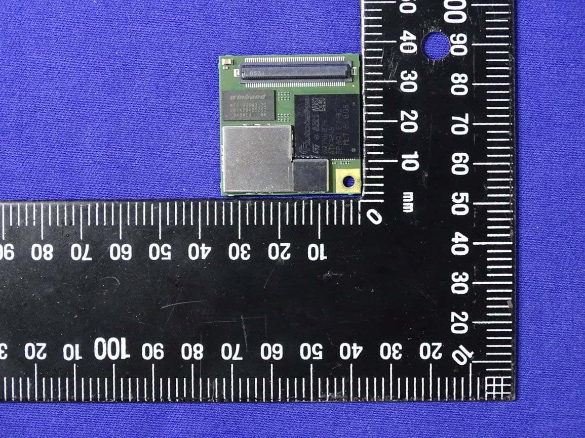
NUK-VTX3012
May 07, 2020V2X DSRC Module
Equipment Class
TNB - Licensed Non-Broadcast Station Transmitter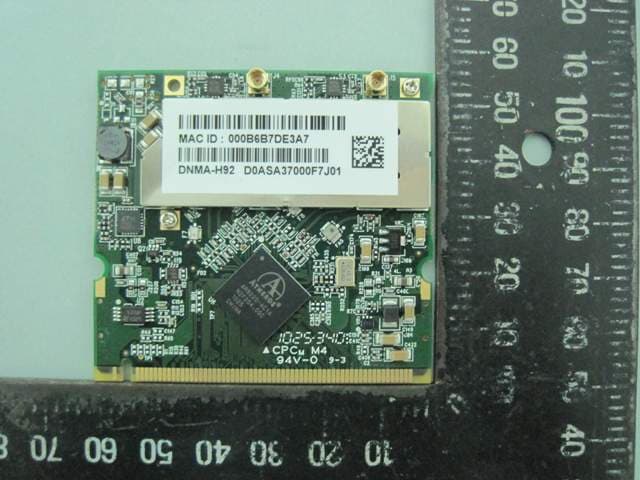
NUK-DNMAH92
Oct 06, 2010WLAN 802.11a/b/g/n Mini-PCI module
Equipment Class
NII - Unlicensed National Information Infrastructure TX
NUKWBRISW0504
Nov 06, 2003WIRELESS BROADBAND ROUTER
Equipment Class
DTS - Digital Transmission System
NUKISCCM020
Oct 07, 1998JBP - Part 15 Class B Computing Device Peripheral
Equipment Class
JBP - Part 15 Class B Computing Device Peripheral